
Installation Guide
Page 5
Contents 4 C H A P T E R A A P P E N D I X B A P P E N D I X C A P P E N D I X Removal and Replacement Procedures 4-1 Removing and Installing the DC-Input Power Supply 4-2 Required Tools 4-2 Removing the DC-Input Power Supply 4-2 Installing the DC-Input Power Supply 4-5 Removing and ... (For Connecting to a PC) B-12 Troubleshooting the Installation C-1 Getting Started C-2 Problem Solving to the System Component Level C-2 Identifying Startup Problems C-2 LED Readings C-3 OL-21561-02 Catalyst 4948E and Catalyst 4948E-F Switch Installation Guide v
Contents 4 C H A P T E R A A P P E N D I X B A P P E N D I X C A P P E N D I X Removal and Replacement Procedures 4-1 Removing and Installing the DC-Input Power Supply 4-2 Required Tools 4-2 Removing the DC-Input Power Supply 4-2 Installing the DC-Input Power Supply 4-5 Removing and ... (For Connecting to a PC) B-12 Troubleshooting the Installation C-1 Getting Started C-2 Problem Solving to the System Component Level C-2 Identifying Startup Problems C-2 LED Readings C-3 OL-21561-02 Catalyst 4948E and Catalyst 4948E-F Switch Installation Guide v

Installation Guide
Page 6
...Disconnecting Device D-25 Statement 1030-Equipment Installation D-26 Statement 1040-Product Disposal D-28 Statement 1045-Short-circuit Protection D-30 Statement 1046-Installing or Replacing the Unit D-32 Statement 1051-Laser Radiation D-33 Statement 1072-Shock Hazard from Interconnections D-35 Statement 1074-Comply with Local and National Electrical ... Bonding Networks D-42 Statement 7014-Installation Location D-42 Statement 7015-Equipment Bonding and Grounding D-42 Statement 7016-Battery Return Conductor D-42 Catalyst 4948E and Catalyst 4948E-F Switch Installation Guide vi OL-21561-02
...Disconnecting Device D-25 Statement 1030-Equipment Installation D-26 Statement 1040-Product Disposal D-28 Statement 1045-Short-circuit Protection D-30 Statement 1046-Installing or Replacing the Unit D-32 Statement 1051-Laser Radiation D-33 Statement 1072-Shock Hazard from Interconnections D-35 Statement 1074-Comply with Local and National Electrical ... Bonding Networks D-42 Statement 7014-Installation Location D-42 Statement 7015-Equipment Bonding and Grounding D-42 Statement 7016-Battery Return Conductor D-42 Catalyst 4948E and Catalyst 4948E-F Switch Installation Guide vi OL-21561-02

Installation Guide
Page 9
... adapters supplied with the Catalyst 4948E and Catalyst 4948E-F switches. Preface This preface describes the audience, organization, and conventions of the Catalyst 4948E and Catalyst 4948E-F Switch Installation Guide and provides information on the Catalyst 4948E and Catalyst 4948E-F switches. Organization This guide is organized as defined in IEC60950-1 and AZ/NZS 60950-1) should install, replace, or service the equipment...
... adapters supplied with the Catalyst 4948E and Catalyst 4948E-F switches. Preface This preface describes the audience, organization, and conventions of the Catalyst 4948E and Catalyst 4948E-F Switch Installation Guide and provides information on the Catalyst 4948E and Catalyst 4948E-F switches. Organization This guide is organized as defined in IEC60950-1 and AZ/NZS 60950-1) should install, replace, or service the equipment...

Installation Guide
Page 29
..., page 2-13 Tip For additional information about the Cisco Catalyst 4948E or the Catalyst 4948E-F switch (including configuration examples and troubleshooting information), see the documents listed on this page: http://www.cisco.com/en/US/products/ps6021/tsd_products_support_series_home.html Safety Safety ...difficult to install, replace, or service this publication in restricted access areas. The warnings below are general warnings that may harm you if performed incorrectly. 2 C H A P T E R Preparing for Installation Planning a proper location for the switch and the layout ...
..., page 2-13 Tip For additional information about the Cisco Catalyst 4948E or the Catalyst 4948E-F switch (including configuration examples and troubleshooting information), see the documents listed on this page: http://www.cisco.com/en/US/products/ps6021/tsd_products_support_series_home.html Safety Safety ...difficult to install, replace, or service this publication in restricted access areas. The warnings below are general warnings that may harm you if performed incorrectly. 2 C H A P T E R Preparing for Installation Planning a proper location for the switch and the layout ...

Installation Guide
Page 31
...and into the air intakes of the rack. - Chapter 2 Preparing for maintenance and removal of gravity and prevent the rack from field-replaceable components to become loose in the lower half of the rack to overheat. Ensure that equipment installed near the top of equipment above. ... rack. • Do not place the chassis within 1 foot (30.45 cm) of the chassis. use an open . - OL-21561-02 Catalyst 4948E and Catalyst 4948E-F Switch Installation Guide 2-3 Ensure that is thinner. • Clean the installation site at least 3 to 4 feet (91.4 to 121.9 cm) of clearance...
...and into the air intakes of the rack. - Chapter 2 Preparing for maintenance and removal of gravity and prevent the rack from field-replaceable components to become loose in the lower half of the rack to overheat. Ensure that equipment installed near the top of equipment above. ... rack. • Do not place the chassis within 1 foot (30.45 cm) of the chassis. use an open . - OL-21561-02 Catalyst 4948E and Catalyst 4948E-F Switch Installation Guide 2-3 Ensure that is thinner. • Clean the installation site at least 3 to 4 feet (91.4 to 121.9 cm) of clearance...
Installation Guide
Page 45
... 1 laser product. Install only in restricted access areas. Statement 1045 Warning When installing or replacing the unit, the ground connection must always be allowed to install, replace, or service this equipment. Do not stare into beams or view directly with stabilizing devices,...the bottom of the rack if it is provided with optical instruments. Statement 1074 OL-21561-02 Catalyst 4948E and Catalyst 4948E-F Switch Installation Guide 3-3 Chapter 3 Installing the Switch Preparing to Install the Chassis Warning To prevent bodily injury when mounting or servicing this unit in...
... 1 laser product. Install only in restricted access areas. Statement 1045 Warning When installing or replacing the unit, the ground connection must always be allowed to install, replace, or service this equipment. Do not stare into beams or view directly with stabilizing devices,...the bottom of the rack if it is provided with optical instruments. Statement 1074 OL-21561-02 Catalyst 4948E and Catalyst 4948E-F Switch Installation Guide 3-3 Chapter 3 Installing the Switch Preparing to Install the Chassis Warning To prevent bodily injury when mounting or servicing this unit in...
Installation Guide
Page 55
...of the power cord to the chassis ports. Install only in accordance with a blank power supply cover (Cisco p/n 800-25264-01). Statement 1075 OL-21561-02 Catalyst 4948E and Catalyst 4948E-F Switch Installation Guide 3-13 Note If you have only one power supply installed in place. A restricted access ... the empty power supply bay with national and local wiring regulations. Be sure uninsulated conductors are not in restricted access areas. Always replace cover when terminals are not accessible when cover is intended for installation in service. Step 6 Do not turn on the AC-input...
...of the power cord to the chassis ports. Install only in accordance with a blank power supply cover (Cisco p/n 800-25264-01). Statement 1075 OL-21561-02 Catalyst 4948E and Catalyst 4948E-F Switch Installation Guide 3-13 Note If you have only one power supply installed in place. A restricted access ... the empty power supply bay with national and local wiring regulations. Be sure uninsulated conductors are not in restricted access areas. Always replace cover when terminals are not accessible when cover is intended for installation in service. Step 6 Do not turn on the AC-input...
Installation Guide
Page 59
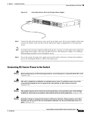
... and Catalyst 4948E-F Switch Installation Guide 3-17 Step 3 Check the label on the SFP transceiver body to the ESD ground connector or a bare metal surface on your Cisco device. Step 6 Holding it as shown in Figure 3-10, insert the SFP into the socket until directed to do so later in...are installing the SFP transceiver in the correct orientation for your network. Note On some SFP transceivers, the TX and RX marking might be replaced by arrowheads pointing from its protective packaging. Ensure that you have the correct model for your chassis. Remove the SFP transceiver from the ...
... and Catalyst 4948E-F Switch Installation Guide 3-17 Step 3 Check the label on the SFP transceiver body to the ESD ground connector or a bare metal surface on your Cisco device. Step 6 Holding it as shown in Figure 3-10, insert the SFP into the socket until directed to do so later in...are installing the SFP transceiver in the correct orientation for your network. Note On some SFP transceivers, the TX and RX marking might be replaced by arrowheads pointing from its protective packaging. Ensure that you have the correct model for your chassis. Remove the SFP transceiver from the ...

Installation Guide
Page 65
... and qualified personnel should be allowed to install, replace, or service this page: http://www.cisco.com/en/US/products/ps6021/tsd_products_support_series_home.html The chassis FRUs and their associated part numbers are listed in Table 4-1. Statement 1030 Tip For additional information about the Cisco Catalyst 4948E switch (including configuration examples and troubleshooting information), see the...
... and qualified personnel should be allowed to install, replace, or service this page: http://www.cisco.com/en/US/products/ps6021/tsd_products_support_series_home.html The chassis FRUs and their associated part numbers are listed in Table 4-1. Statement 1030 Tip For additional information about the Cisco Catalyst 4948E switch (including configuration examples and troubleshooting information), see the...

Installation Guide
Page 66
..., page 4-2 • Installing the DC-Input Power Supply, page 4-5 Note The Catalyst 4948E-F chassis does not support the PWR-C49-300DC DC-input power supply. Catalyst 4948E and Catalyst 4948E-F Switch Installation Guide 4-2 OL-21561-02 Statement 1046 Required Tools To perform this procedure, you... DC-Input Power Supply Chapter 4 Removal and Replacement Procedures Removing and Installing the DC-Input Power Supply This section describes how to remove and install the DC-input power supplies (PWR-C49-300DC) in the Catalyst 4948E switch chassis and contains these steps: Step 1 Step...
..., page 4-2 • Installing the DC-Input Power Supply, page 4-5 Note The Catalyst 4948E-F chassis does not support the PWR-C49-300DC DC-input power supply. Catalyst 4948E and Catalyst 4948E-F Switch Installation Guide 4-2 OL-21561-02 Statement 1046 Required Tools To perform this procedure, you... DC-Input Power Supply Chapter 4 Removal and Replacement Procedures Removing and Installing the DC-Input Power Supply This section describes how to remove and install the DC-input power supplies (PWR-C49-300DC) in the Catalyst 4948E switch chassis and contains these steps: Step 1 Step...

Installation Guide
Page 67
...supply terminal block in place with one hand, and slide the power supply halfway out of the power supply. Chapter 4 Removal and Replacement Procedures Removing and Installing the DC-Input Power Supply Step 3 Step 4 Step 5 Disconnect the DC-input cables from the ground ...terminal Loosen the captive installation screw on the front edge) of the chassis. Set the power supply aside. OL-21561-02 Catalyst 4948E and Catalyst 4948E-F Switch Installation Guide 4-3 Positive (+) source DC cable from the negative (-) terminal 3. Step 6 If the power supply bay is equipped...
...supply terminal block in place with one hand, and slide the power supply halfway out of the power supply. Chapter 4 Removal and Replacement Procedures Removing and Installing the DC-Input Power Supply Step 3 Step 4 Step 5 Disconnect the DC-input cables from the ground ...terminal Loosen the captive installation screw on the front edge) of the chassis. Set the power supply aside. OL-21561-02 Catalyst 4948E and Catalyst 4948E-F Switch Installation Guide 4-3 Positive (+) source DC cable from the negative (-) terminal 3. Step 6 If the power supply bay is equipped...
Installation Guide
Page 68
... INPUT OK OUTPUT OK Chapter 4 Removal and Replacement Procedures 278171 + - C49-300DC -48 To 8A -60VAC INPUT OK OUTPUT OK 1 Detach the power leads from the terminal block in the following order: • (+) positive • (-) negative • Ground 2 Loosen captive installation screw Catalyst 4948E and Catalyst 4948E-F Switch Installation Guide 4-4 OL-21561-02 PWR...
... INPUT OK OUTPUT OK Chapter 4 Removal and Replacement Procedures 278171 + - C49-300DC -48 To 8A -60VAC INPUT OK OUTPUT OK 1 Detach the power leads from the terminal block in the following order: • (+) positive • (-) negative • Ground 2 Loosen captive installation screw Catalyst 4948E and Catalyst 4948E-F Switch Installation Guide 4-4 OL-21561-02 PWR...
Installation Guide
Page 69
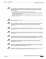
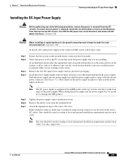
...makes contact with the chassis power connector. (See Figure 4-2.) Press firmly on the power supply faceplate to fully seat the power supply in the Catalyst 4948E switch, follow these steps: Step 1 Step 2 Step 3 Step 4 Ensure that the system (earth) ground chassis connection has been made first and...the DC circuits. Turn OFF the DC power line circuit breakers and remove the DC power line fuses. Chapter 4 Removal and Replacement Procedures Removing and Installing the DC-Input Power Supply Installing the DC-Input Power Supply Warning Before performing any of the following procedures,...
...makes contact with the chassis power connector. (See Figure 4-2.) Press firmly on the power supply faceplate to fully seat the power supply in the Catalyst 4948E switch, follow these steps: Step 1 Step 2 Step 3 Step 4 Ensure that the system (earth) ground chassis connection has been made first and...the DC circuits. Turn OFF the DC power line circuit breakers and remove the DC power line fuses. Chapter 4 Removal and Replacement Procedures Removing and Installing the DC-Input Power Supply Installing the DC-Input Power Supply Warning Before performing any of the following procedures,...

Installation Guide
Page 70
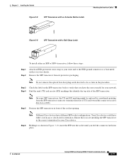
... by ensuring that the INPUT OK and the OUTPUT OK LEDs on the terminal block After ensuring that all wire connections are both green. Catalyst 4948E and Catalyst 4948E-F Switch Installation Guide 4-6 OL-21561-02 Positive (+) source DC cable to a separate power source. Note In a system with dual power supplies, connect ...the power supply front panel are secure, reinstall the plastic terminal block cover. Removing and Installing the DC-Input Power Supply Chapter 4 Removal and Replacement Procedures Step 8 Step 9 Connect the DC-input wires to the terminal block in this order: 1.
... by ensuring that the INPUT OK and the OUTPUT OK LEDs on the terminal block After ensuring that all wire connections are both green. Catalyst 4948E and Catalyst 4948E-F Switch Installation Guide 4-6 OL-21561-02 Positive (+) source DC cable to a separate power source. Note In a system with dual power supplies, connect ...the power supply front panel are secure, reinstall the plastic terminal block cover. Removing and Installing the DC-Input Power Supply Chapter 4 Removal and Replacement Procedures Step 8 Step 9 Connect the DC-input wires to the terminal block in this order: 1.

Installation Guide
Page 71
C49-300DC -48 To 8A -60VAC INPUT OK OUTPUT OK + - 2 PWR - Chapter 4 Removal and Replacement Procedures Figure 4-2 Installing the DC-Input Power Supply + - PWR - C49-300DC -48 To 8A -60VAC INPUT OK OUTPUT OK 1 Secure the ... C49-300DC -48 To 8A -60VAC INPUT OK OUTPUT OK 1 + - following order: • Ground • (-) negative • (+) positive OL-21561-02 Catalyst 4948E and Catalyst 4948E-F Switch Installation Guide 4-7 PWR - PWR - C49-300DC -48 To 8A -60VAC INPUT OK OUTPUT OK Removing and Installing the DC-Input Power Supply 278172 + -
C49-300DC -48 To 8A -60VAC INPUT OK OUTPUT OK + - 2 PWR - Chapter 4 Removal and Replacement Procedures Figure 4-2 Installing the DC-Input Power Supply + - PWR - C49-300DC -48 To 8A -60VAC INPUT OK OUTPUT OK 1 Secure the ... C49-300DC -48 To 8A -60VAC INPUT OK OUTPUT OK 1 + - following order: • Ground • (-) negative • (+) positive OL-21561-02 Catalyst 4948E and Catalyst 4948E-F Switch Installation Guide 4-7 PWR - PWR - C49-300DC -48 To 8A -60VAC INPUT OK OUTPUT OK Removing and Installing the DC-Input Power Supply 278172 + -
Installation Guide
Page 72
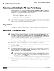
... (See Figure 4-3.) Set the power supply aside. Catalyst 4948E and Catalyst 4948E-F Switch Installation Guide 4-8 OL-21561-02 Step 5 If the power supply bay is adequate working space within the air duct to perform the removal and replacement steps. They are not interchangeable between the two chassis...AC-Input Power Supply Chapter 4 Removal and Replacement Procedures Removing and Installing the AC-Input Power Supply This section describes how to remove and install the AC-input power supply (PWR-C49E-300AC-R) in the Catalyst 4948E switch chassis or the AC-input power supply (PWR...
... (See Figure 4-3.) Set the power supply aside. Catalyst 4948E and Catalyst 4948E-F Switch Installation Guide 4-8 OL-21561-02 Step 5 If the power supply bay is adequate working space within the air duct to perform the removal and replacement steps. They are not interchangeable between the two chassis...AC-Input Power Supply Chapter 4 Removal and Replacement Procedures Removing and Installing the AC-Input Power Supply This section describes how to remove and install the AC-input power supply (PWR-C49E-300AC-R) in the Catalyst 4948E switch chassis or the AC-input power supply (PWR...
Installation Guide
Page 73
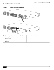
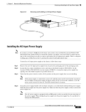
...(WS-X4994= for the Catalyst 4948E or WS-X4994-F= for possible future use. To clear this condition, cycle the power on/off switch off (0) position on the power supply that you do not need to remove the air duct or the switch chassis in order to remove and replace the AC-input power supply...- 3A 50 - 60 Hz INPUT OK OUTPUT OK 278173 Installing the AC-Input Power Supply Note If you have a Catalyst 4948E-F switch chassis and you have also installed the optional Panduit ToR Switch Inlet Duct (model CDE2) to extend the chassis's air intake, you are installing. To install an AC-input power ...
...(WS-X4994= for the Catalyst 4948E or WS-X4994-F= for possible future use. To clear this condition, cycle the power on/off switch off (0) position on the power supply that you do not need to remove the air duct or the switch chassis in order to remove and replace the AC-input power supply...- 3A 50 - 60 Hz INPUT OK OUTPUT OK 278173 Installing the AC-Input Power Supply Note If you have a Catalyst 4948E-F switch chassis and you have also installed the optional Panduit ToR Switch Inlet Duct (model CDE2) to extend the chassis's air intake, you are installing. To install an AC-input power ...
Installation Guide
Page 74
... the user or damage to perform the removal and replacement steps. Let the fan blades completely stop before you do not need to remove the air duct or the switch chassis in the Catalyst 4948E switch chassis and contains these steps: 4-10 Catalyst 4948E and Catalyst 4948E-F Switch Installation Guide OL-21561-02 Statement 258 To remove...
... the user or damage to perform the removal and replacement steps. Let the fan blades completely stop before you do not need to remove the air duct or the switch chassis in the Catalyst 4948E switch chassis and contains these steps: 4-10 Catalyst 4948E and Catalyst 4948E-F Switch Installation Guide OL-21561-02 Statement 258 To remove...

Installation Guide
Page 75
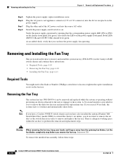
...the Fan Tray Note You have 30 seconds to install the replacement fan tray before the system automatically shuts down. OL-21561-02 Catalyst 4948E and Catalyst 4948E-F Switch Installation Guide 4-11 Chapter 4 Removal and Replacement Procedures Removing and Installing the Fan Tray Step 1 Step ...2 Step 3 Step 4 Remove the replacement fan tray from the chassis connector. (See Figure...
...the Fan Tray Note You have 30 seconds to install the replacement fan tray before the system automatically shuts down. OL-21561-02 Catalyst 4948E and Catalyst 4948E-F Switch Installation Guide 4-11 Chapter 4 Removal and Replacement Procedures Removing and Installing the Fan Tray Step 1 Step ...2 Step 3 Step 4 Remove the replacement fan tray from the chassis connector. (See Figure...

Installation Guide
Page 76
Removing and Installing the Fan Tray Chapter 4 Removal and Replacement Procedures 4-12 Catalyst 4948E and Catalyst 4948E-F Switch Installation Guide OL-21561-02
Removing and Installing the Fan Tray Chapter 4 Removal and Replacement Procedures 4-12 Catalyst 4948E and Catalyst 4948E-F Switch Installation Guide OL-21561-02