
Installation Guide
Page 3
... 1-1 Features 1-3 Physical and Environmental Specifications 1-7 Fan Tray 1-8 Catalyst 4948E Fan Tray (WS-X4993=) 1-8 Catalyst 4948E-F Fan Tray (WS-X4993-F=) 1-9 Front Panel LEDs 1-...11 Preparing for Installation 2-1 Safety 2-1 Site Requirements 2-2 Rack-Mounting Guidelines 2-2 Temperature 2-3 Air Flow 2-4 Humidity 2-5 Altitude 2-5 Dust and Particulates 2-5 Corrosion 2-6 Electromagnetic and Radio Frequency Interference 2-6 Shock and Vibration 2-7 Power Source Interruptions 2-7 OL-21561-02 Catalyst 4948E and Catalyst 4948E-F Switch...
... 1-1 Features 1-3 Physical and Environmental Specifications 1-7 Fan Tray 1-8 Catalyst 4948E Fan Tray (WS-X4993=) 1-8 Catalyst 4948E-F Fan Tray (WS-X4993-F=) 1-9 Front Panel LEDs 1-...11 Preparing for Installation 2-1 Safety 2-1 Site Requirements 2-2 Rack-Mounting Guidelines 2-2 Temperature 2-3 Air Flow 2-4 Humidity 2-5 Altitude 2-5 Dust and Particulates 2-5 Corrosion 2-6 Electromagnetic and Radio Frequency Interference 2-6 Shock and Vibration 2-7 Power Source Interruptions 2-7 OL-21561-02 Catalyst 4948E and Catalyst 4948E-F Switch...

Installation Guide
Page 4
...the Cable Guide (Optional) 3-8 Installing the Catalyst 4948E-F Switch Chassis with the Optional Panduit Air Duct Kit 3-9 Installing the System Ground 3-10 Connecting Power to the Switch 3-12 Connecting AC Source Power to the Switch 3-12 Connecting DC Source Power to the Switch 3-13 Attaching the Interface Cables 3-15 ...and Cables 3-16 Connecting to the Ethernet Management Port 3-20 Connecting to the Console Port 3-20 Powering Up the Switch 3-21 Starting the Terminal-Emulation Software 3-21 Powering Up the Switch 3-21 Catalyst 4948E and Catalyst 4948E-F Switch Installation Guide iv OL-21561-02
...the Cable Guide (Optional) 3-8 Installing the Catalyst 4948E-F Switch Chassis with the Optional Panduit Air Duct Kit 3-9 Installing the System Ground 3-10 Connecting Power to the Switch 3-12 Connecting AC Source Power to the Switch 3-12 Connecting DC Source Power to the Switch 3-13 Attaching the Interface Cables 3-15 ...and Cables 3-16 Connecting to the Ethernet Management Port 3-20 Connecting to the Console Port 3-20 Powering Up the Switch 3-21 Starting the Terminal-Emulation Software 3-21 Powering Up the Switch 3-21 Catalyst 4948E and Catalyst 4948E-F Switch Installation Guide iv OL-21561-02

Installation Guide
Page 5
... Tools 4-10 Removing the Fan Tray 4-10 Installing the Fan Tray 4-11 Power Supply Specifications A-1 300 W AC-Input Power Supply (PWR-C49E-300AC-R) A-1 300 W AC-Input Power Supply (PWR-C49E-300AC-F) A-5 300 W AC-Input Power Supply Power Cords A-8 300 W DC-Input Power Supply (PWR-C49-300DC) A-12 Transceiver, Chassis Connectors, and Cable and ... to a PC) B-12 Troubleshooting the Installation C-1 Getting Started C-2 Problem Solving to the System Component Level C-2 Identifying Startup Problems C-2 LED Readings C-3 OL-21561-02 Catalyst 4948E and Catalyst 4948E-F Switch Installation Guide v
... Tools 4-10 Removing the Fan Tray 4-10 Installing the Fan Tray 4-11 Power Supply Specifications A-1 300 W AC-Input Power Supply (PWR-C49E-300AC-R) A-1 300 W AC-Input Power Supply (PWR-C49E-300AC-F) A-5 300 W AC-Input Power Supply Power Cords A-8 300 W DC-Input Power Supply (PWR-C49-300DC) A-12 Transceiver, Chassis Connectors, and Cable and ... to a PC) B-12 Troubleshooting the Installation C-1 Getting Started C-2 Problem Solving to the System Component Level C-2 Identifying Startup Problems C-2 LED Readings C-3 OL-21561-02 Catalyst 4948E and Catalyst 4948E-F Switch Installation Guide v

Installation Guide
Page 6
...D-35 Statement 1074-Comply with Local and National Electrical Codes D-37 Statement 1075-Hazardous Voltage or Energy Present on DC Power Terminals D-39 Regulatory Standards Compliance D-40 GR-1089-CORE Issue 3 Documentation Statements D-41 Statement 7016-GR-1089-Core Intrabuilding...AC Power Fault D-42 Statement 7012-Equipment Interfacing with AC Power Ports D-42 Statement 7013-Equipment Bonding Networks D-42 Statement 7014-Installation Location D-42 Statement 7015-Equipment Bonding and Grounding D-42 Statement 7016-Battery Return Conductor D-42 Catalyst 4948E and Catalyst 4948E-F Switch ...
...D-35 Statement 1074-Comply with Local and National Electrical Codes D-37 Statement 1075-Hazardous Voltage or Energy Present on DC Power Terminals D-39 Regulatory Standards Compliance D-40 GR-1089-CORE Issue 3 Documentation Statements D-41 Statement 7016-GR-1089-Core Intrabuilding...AC Power Fault D-42 Statement 7012-Equipment Interfacing with AC Power Ports D-42 Statement 7013-Equipment Bonding Networks D-42 Statement 7014-Installation Location D-42 Statement 7015-Equipment Bonding and Grounding D-42 Statement 7016-Battery Return Conductor D-42 Catalyst 4948E and Catalyst 4948E-F Switch ...

Installation Guide
Page 7
... A Notice for Taiwan and Other Traditional Chinese Markets D-45 Statement 294-Class A Warning for Korea D-45 Statement 340-Class A Warning for CISPR22 D-45 Statement 371-Power Cable and AC Adapter D-47 OL-21561-02 Catalyst 4948E and Catalyst 4948E-F Switch Installation Guide vii
... A Notice for Taiwan and Other Traditional Chinese Markets D-45 Statement 294-Class A Warning for Korea D-45 Statement 340-Class A Warning for CISPR22 D-45 Statement 371-Power Cable and AC Adapter D-47 OL-21561-02 Catalyst 4948E and Catalyst 4948E-F Switch Installation Guide vii

Installation Guide
Page 9
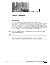
... Chapter Title Description Chapter 1 Product Overview Describes the hardware features, specifications, and functionality of the Catalyst 4948E and Catalyst 4948E-F switches. Appendix B Transceiver, Chassis Connectors, and Cable and Adapter Specifications Describes the SFP and SFP+ ...with the Catalyst 4948E and Catalyst 4948E-F switches. Chapter 4 Appendix A Removal and Replacement Procedures Power Supply Specifications Describes how to rack-mount the Catalyst 4948E and the Catalyst 4948E-F switches and attach the cables. Chapter 3 Installing the Switch Describes how...
... Chapter Title Description Chapter 1 Product Overview Describes the hardware features, specifications, and functionality of the Catalyst 4948E and Catalyst 4948E-F switches. Appendix B Transceiver, Chassis Connectors, and Cable and Adapter Specifications Describes the SFP and SFP+ ...with the Catalyst 4948E and Catalyst 4948E-F switches. Chapter 4 Appendix A Removal and Replacement Procedures Power Supply Specifications Describes how to rack-mount the Catalyst 4948E and the Catalyst 4948E-F switches and attach the cables. Chapter 3 Installing the Switch Describes how...
Installation Guide
Page 17
... ports and 4 1-GB or 10-GB uplink ports. Note The fan trays and the power supplies are 1-RU, horizontal, fixed-configuration chassis with the major features identified. Tip For additional information about the Cisco Catalyst 4948E and the Catalyst 4948E-F switches (including configuration examples and troubleshooting information), see the documents listed on this page: http...
... ports and 4 1-GB or 10-GB uplink ports. Note The fan trays and the power supplies are 1-RU, horizontal, fixed-configuration chassis with the major features identified. Tip For additional information about the Cisco Catalyst 4948E and the Catalyst 4948E-F switches (including configuration examples and troubleshooting information), see the documents listed on this page: http...
Installation Guide
Page 19
... INPUT OK OUTPUT OK 1 2 PWR - 540 AC 100 - 240 VAC 7 - 3A 50 - 60 Hz INPUT OK OUTPUT OK 3 1 Power supply 1 (primary) 2 Fan tray 3 Power supply 2 (redundant) This chapter describes the Catalyst 4948E and Catalyst 4948E-F switches and includes these sections: • Features, page 1-3 • Physical and Environmental Specifications, page 1-7 • Fan Tray, page 1-8 • Front...
... INPUT OK OUTPUT OK 1 2 PWR - 540 AC 100 - 240 VAC 7 - 3A 50 - 60 Hz INPUT OK OUTPUT OK 3 1 Power supply 1 (primary) 2 Fan tray 3 Power supply 2 (redundant) This chapter describes the Catalyst 4948E and Catalyst 4948E-F switches and includes these sections: • Features, page 1-3 • Physical and Environmental Specifications, page 1-7 • Fan Tray, page 1-8 • Front...
Installation Guide
Page 20
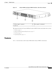
... Specifications" contains additional information for the port to remote servers for the console port. Features Chapter 1 Product Overview Table 1-1 Catalyst 4948E and Catalyst 4948E-F Switch Features Feature Chassis (both chassis) Uplink ports (both chassis) Downlink ports (both chassis) Console port (both chassis) Ethernet ...RU, 48 10/100/1000 ports plus 4 1-GB/10-GB ports, fixed configuration switch with each port is not provided in the accessory kit. A bicolor port link status LED is associated with redundant power supplies The chassis has 4 1-GB or 10-GB uplink ports.
... Specifications" contains additional information for the port to remote servers for the console port. Features Chapter 1 Product Overview Table 1-1 Catalyst 4948E and Catalyst 4948E-F Switch Features Feature Chassis (both chassis) Uplink ports (both chassis) Downlink ports (both chassis) Console port (both chassis) Ethernet ...RU, 48 10/100/1000 ports plus 4 1-GB/10-GB ports, fixed configuration switch with each port is not provided in the accessory kit. A bicolor port link status LED is associated with redundant power supplies The chassis has 4 1-GB or 10-GB uplink ports.

Installation Guide
Page 21
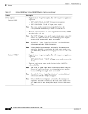
...fan tray status. - Chapter 1 Product Overview Features Table 1-1 Catalyst 4948E and Catalyst 4948E-F Switch Features (continued) Feature RESET switch (both chassis) Fan tray Catalyst 4948E chassis Description • Resets and restarts the switch. • The switch is recessed on the chassis front panel) that provides fan ...thermal sensors are positioned near the air inlet (rear of thermal sensors are not interchangeable between the two power supplies. • The fan tray for the Catalyst 4948E (WS-X4993=) is from front to back. • The chassis has a FAN LED (located...
...fan tray status. - Chapter 1 Product Overview Features Table 1-1 Catalyst 4948E and Catalyst 4948E-F Switch Features (continued) Feature RESET switch (both chassis) Fan tray Catalyst 4948E chassis Description • Resets and restarts the switch. • The switch is recessed on the chassis front panel) that provides fan ...thermal sensors are positioned near the air inlet (rear of thermal sensors are not interchangeable between the two power supplies. • The fan tray for the Catalyst 4948E (WS-X4993=) is from front to back. • The chassis has a FAN LED (located...
Installation Guide
Page 22
...; The front panel on the power supply for the Catalyst 4948E are not interchangeable between multiple power supplies because all AC power supply inputs are supported: - Features Chapter 1 Product Overview Table 1-1 Catalyst 4948E and Catalyst 4948E-F Switch Features (continued) Feature Power supplies Catalyst 4948E Description • Supports one or two power supplies. Note The power supplies are color-coded dark grey...
...; The front panel on the power supply for the Catalyst 4948E are not interchangeable between multiple power supplies because all AC power supply inputs are supported: - Features Chapter 1 Product Overview Table 1-1 Catalyst 4948E and Catalyst 4948E-F Switch Features (continued) Feature Power supplies Catalyst 4948E Description • Supports one or two power supplies. Note The power supplies are color-coded dark grey...
Installation Guide
Page 23
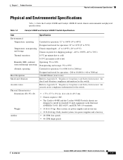
... Compliance and Safety Information" for acoustic noise compliance information for the switch. Base system; two power supplies and a fan tray. • 28 CFM (low speed) • 44 CFM (high speed) OL-21561-02 Catalyst 4948E and Catalyst 4948E-F Switch Installation Guide 1-7 Table 1-2 Catalyst 4948E and Catalyst 4948E-F Switch Specifications Item Environmental Temperature, operating Temperature, nonoperating and storage Thermal...
... Compliance and Safety Information" for acoustic noise compliance information for the switch. Base system; two power supplies and a fan tray. • 28 CFM (low speed) • 44 CFM (high speed) OL-21561-02 Catalyst 4948E and Catalyst 4948E-F Switch Installation Guide 1-7 Table 1-2 Catalyst 4948E and Catalyst 4948E-F Switch Specifications Item Environmental Temperature, operating Temperature, nonoperating and storage Thermal...
Installation Guide
Page 24
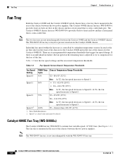
...in the rear of the chassis between the two power supplies. There are not interchangeable between the Catalyst 4948E and the Catalyst 4948E-F chassis. Fan Tray Chapter 1 Product Overview Fan Tray Both the Catalyst 4948E and the Catalyst 4948E-F switch chassis have a fan tray that is mounted ...in the rear of the chassis between the two power supplies. Note The ...
...in the rear of the chassis between the two power supplies. There are not interchangeable between the Catalyst 4948E and the Catalyst 4948E-F chassis. Fan Tray Chapter 1 Product Overview Fan Tray Both the Catalyst 4948E and the Catalyst 4948E-F switch chassis have a fan tray that is mounted ...in the rear of the chassis between the two power supplies. Note The ...
Installation Guide
Page 25
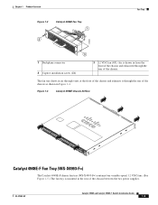
...chassis and exhausts it through the rear of the chassis. OL-21561-02 Catalyst 4948E and Catalyst 4948E-F Switch Installation Guide 1-9 Chapter 1 Product Overview Figure 1-3 Catalyst 4948E Fan Tray 1 2 Fan Tray 278085 3 1 Backplane connector 2 ...Captive installation screw (2X) 3 12 VDC fan (4X). The fan tray draws in from the front of the chassis and exhausted through the rear of the chassis between the two power...
...chassis and exhausts it through the rear of the chassis. OL-21561-02 Catalyst 4948E and Catalyst 4948E-F Switch Installation Guide 1-9 Chapter 1 Product Overview Figure 1-3 Catalyst 4948E Fan Tray 1 2 Fan Tray 278085 3 1 Backplane connector 2 ...Captive installation screw (2X) 3 12 VDC fan (4X). The fan tray draws in from the front of the chassis and exhausted through the rear of the chassis between the two power...
Installation Guide
Page 27
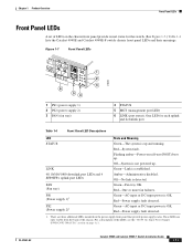
.... 48 10/100/1000 downlink port LEDs and 4 SFP/SFP+ uplink port LEDs Amber-Administrative disabled. PS2 (Power supply 2)1 Green-AC-input or DC-input power is not powered up . One LED for the switch. (See Figure 1-7.) Table 1-4 lists the Catalyst 4948E and Catalyst 4948E-F switch chassis front panel LEDs and their meanings. Off-System is OK.
.... 48 10/100/1000 downlink port LEDs and 4 SFP/SFP+ uplink port LEDs Amber-Administrative disabled. PS2 (Power supply 2)1 Green-AC-input or DC-input power is not powered up . One LED for the switch. (See Figure 1-7.) Table 1-4 lists the Catalyst 4948E and Catalyst 4948E-F switch chassis front panel LEDs and their meanings. Off-System is OK.

Installation Guide
Page 29
... sections: • Safety, page 2-1 • Site Requirements, page 2-2 • System Grounding, page 2-7 • Power Requirements, page 2-11 • Cabling Requirements, page 2-13 • Site Preparation Checklist, page 2-13 Tip For additional information about the Cisco Catalyst 4948E or the Catalyst 4948E-F switch (including configuration examples and troubleshooting information), see the documents listed on this page...
... sections: • Safety, page 2-1 • Site Requirements, page 2-2 • System Grounding, page 2-7 • Power Requirements, page 2-11 • Cabling Requirements, page 2-13 • Site Preparation Checklist, page 2-13 Tip For additional information about the Cisco Catalyst 4948E or the Catalyst 4948E-F switch (including configuration examples and troubleshooting information), see the documents listed on this page...
Installation Guide
Page 30
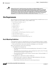
... suitable for use of a special tool, lock and key or other means of the hazard. Ensure that you bolt the rack to install your Catalyst 4948E or Catalyst 4948E-F switch: • Rack-Mounting Guidelines, page 2-2 • Temperature, page 2-3 • Air Flow, page 2-4 • Humidity, page 2-5 •... within the restricted access location are made aware of security. We recommend that present a shock hazard may exist on Power over . - Catalyst 4948E and Catalyst 4948E-F Switch Installation Guide 2-2 OL-21561-02 A restricted access area can be 17.75 inches (45.09 cm). - Mount...
... suitable for use of a special tool, lock and key or other means of the hazard. Ensure that you bolt the rack to install your Catalyst 4948E or Catalyst 4948E-F switch: • Rack-Mounting Guidelines, page 2-2 • Temperature, page 2-3 • Air Flow, page 2-4 • Humidity, page 2-5 •... within the restricted access location are made aware of security. We recommend that present a shock hazard may exist on Power over . - Catalyst 4948E and Catalyst 4948E-F Switch Installation Guide 2-2 OL-21561-02 A restricted access area can be 17.75 inches (45.09 cm). - Mount...

Installation Guide
Page 31
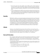
...cause a variety of problems, including premature aging and failure of chips, and failure of mechanical devices. OL-21561-02 Catalyst 4948E and Catalyst 4948E-F Switch Installation Guide 2-3 Chassis mounted higher in a rack enclosure are susceptable to higher ambient air temperatures due to the heat...it out when necessary for equipment maintenance or upgrades. - If the switch is provided with the rack open rack whenever possible. - Allow at least 3 to 4 feet (91.4 to the power supplies or switching modules. Ensure that cables from other equipment will receive direct sunlight, ...
...cause a variety of problems, including premature aging and failure of chips, and failure of mechanical devices. OL-21561-02 Catalyst 4948E and Catalyst 4948E-F Switch Installation Guide 2-3 Chassis mounted higher in a rack enclosure are susceptable to higher ambient air temperatures due to the heat...it out when necessary for equipment maintenance or upgrades. - If the switch is provided with the rack open rack whenever possible. - Allow at least 3 to 4 feet (91.4 to the power supplies or switching modules. Ensure that cables from other equipment will receive direct sunlight, ...

Installation Guide
Page 32
...If the difference between chassis can damage internal chassis components. Note The Catalyst 4948E and the Catalyst 4948E-F switches are installing your Catalyst 4948E or Catalyst 4948E-F switch chassis in the hot exhaust air to cool the chassis. Any ...Catalyst 4948E and Catalyst 4948E-F switches are triggered at 104°F (40°C) generating a minor alarm and at the chassis air exhaust grill by taking measurements using external digital temperature probes. Site Requirements Chapter 2 Preparing for chassis that have been exposed to cool the chassis and the power...
...If the difference between chassis can damage internal chassis components. Note The Catalyst 4948E and the Catalyst 4948E-F switches are installing your Catalyst 4948E or Catalyst 4948E-F switch chassis in the hot exhaust air to cool the chassis. Any ...Catalyst 4948E and Catalyst 4948E-F switches are triggered at 104°F (40°C) generating a minor alarm and at the chassis air exhaust grill by taking measurements using external digital temperature probes. Site Requirements Chapter 2 Preparing for chassis that have been exposed to cool the chassis and the power...
Installation Guide
Page 33
...feet (-16 to maintain the humidity within an acceptable range. The standards listed below provide guidelines for future growth. Your Catalyst 4948E or Catalyst 4948E-F switches currently installed in electrical problems related to the cold isle. However, if a system is controlled by air-conditioning in ...the warmer months and by drawing in room temperature air, circulating the air through the power supplies and the chassis, and ...
...feet (-16 to maintain the humidity within an acceptable range. The standards listed below provide guidelines for future growth. Your Catalyst 4948E or Catalyst 4948E-F switches currently installed in electrical problems related to the cold isle. However, if a system is controlled by air-conditioning in ...the warmer months and by drawing in room temperature air, circulating the air through the power supplies and the chassis, and ...
