
Hardware Installation Guide
Page 6
... Analog Telephone, Fax, or Modem 2-15 Connecting a Terminal or PC 2-17 Connecting the Power Supply 2-18 Mounting Your Router 2-18 Mounting on a Table 2-18 Mounting on a Wall 2-19 Verifying Installation 2-20 Where to Go from Here 2-22 Troubleshooting 3-1 Problems During First... Startup 3-2 Problems After First Startup 3-3 Problems After Router Is Running 3-5 When Contacting Your Cisco Reseller 3-7 ISDN and IDSL Concepts A-1 Specifications and Cables B-1...
... Analog Telephone, Fax, or Modem 2-15 Connecting a Terminal or PC 2-17 Connecting the Power Supply 2-18 Mounting Your Router 2-18 Mounting on a Table 2-18 Mounting on a Wall 2-19 Verifying Installation 2-20 Where to Go from Here 2-22 Troubleshooting 3-1 Problems During First... Startup 3-2 Problems After First Startup 3-3 Problems After Router Is Running 3-5 When Contacting Your Cisco Reseller 3-7 ISDN and IDSL Concepts A-1 Specifications and Cables B-1...
Hardware Installation Guide
Page 16
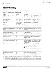
...-8D. You cannot connect S/T devices to IDSL network. Provides connection to Cisco 802 and Cisco 804 routers. 2. Wall-mount feature All Brackets on router bottom provide a way to ISDN S/T network. The Cisco product number for the 8-MB Flash memory upgrade kit is a service port. Table 1-1 Cisco 800 Series Feature Summary Feature 10BASE-T Ethernet port(s) ISDN BRI S/T port...
...-8D. You cannot connect S/T devices to IDSL network. Provides connection to Cisco 802 and Cisco 804 routers. 2. Wall-mount feature All Brackets on router bottom provide a way to ISDN S/T network. The Cisco product number for the 8-MB Flash memory upgrade kit is a service port. Table 1-1 Cisco 800 Series Feature Summary Feature 10BASE-T Ethernet port(s) ISDN BRI S/T port...
Hardware Installation Guide
Page 17
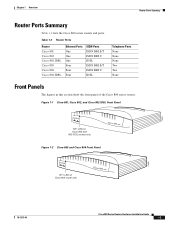
... Table 1-2 lists the Cisco 800 series routers and ports. Figure 1-1 Cisco 801, Cisco 802, and Cisco 802 IDSL Front Panel NT1 LED on Cisco 802 and 802 IDSL routers only Figure 1-2 Cisco 803 and Cisco 804 Front Panel 11665 NT1 LED on Cisco 804 router only 11664 78-5373-04 Cisco 800 Series Routers Hardware Installation Guide 1-3 Table 1-2 Router Ports Router Cisco 801 Cisco 802 Cisco 802 IDSL Cisco 803 Cisco 804 Cisco...
... Table 1-2 lists the Cisco 800 series routers and ports. Figure 1-1 Cisco 801, Cisco 802, and Cisco 802 IDSL Front Panel NT1 LED on Cisco 802 and 802 IDSL routers only Figure 1-2 Cisco 803 and Cisco 804 Front Panel 11665 NT1 LED on Cisco 804 router only 11664 78-5373-04 Cisco 800 Series Routers Hardware Installation Guide 1-3 Table 1-2 Router Ports Router Cisco 801 Cisco 802 Cisco 802 IDSL Cisco 803 Cisco 804 Cisco...
Hardware Installation Guide
Page 21
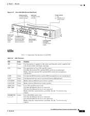
...Table 1-3 summarizes the function of each LED. Table 1-3 LED Functions LED Color OK Green NT1 Green LINE LAN LAN RXD LAN TXD LKØ, LK1, LK2, LK3 Green Green Green Green Green ETHERNET Green 1, 2, 3, 4 Function On when power is supplied to physically secure router.... See the "Troubleshooting" chapter. Off when the Ethernet device is not connected. See the "Troubleshooting" chapter. 78-5373-04 Cisco 800 Series Routers Hardware Installation Guide 1-7 On when the Ethernet device is connected. Blinks when the connection has a problem. Power switch l = On...
...Table 1-3 summarizes the function of each LED. Table 1-3 LED Functions LED Color OK Green NT1 Green LINE LAN LAN RXD LAN TXD LKØ, LK1, LK2, LK3 Green Green Green Green Green ETHERNET Green 1, 2, 3, 4 Function On when power is supplied to physically secure router.... See the "Troubleshooting" chapter. Off when the Ethernet device is not connected. See the "Troubleshooting" chapter. 78-5373-04 Cisco 800 Series Routers Hardware Installation Guide 1-7 On when the Ethernet device is connected. Blinks when the connection has a problem. Power switch l = On...

Hardware Installation Guide
Page 22
...is connected. On back panel of Cisco 801, 802, and 802 IDSL routers only. Cisco 800 Series Routers Hardware Installation Guide 1-8 78-5373-04 For IDSL routers, see the Note following this table. Blinks when packets are sent from the first ISDN B channel. Cisco 803 and 804 routers only. Blinks when the connection has... the first ISDN B channel. On when Ethernet device is in use. Note On Cisco 802 IDSL and Cisco 804 IDSL routers, either CH1 or CH2 is on the first ISDN B channel. LEDs Chapter 1 Overview Table 1-3 LED Functions (continued) LED CH1 CH1 RXD CH1 TXD CH2 CH2 RXD CH2...
...is connected. On back panel of Cisco 801, 802, and 802 IDSL routers only. Cisco 800 Series Routers Hardware Installation Guide 1-8 78-5373-04 For IDSL routers, see the Note following this table. Blinks when packets are sent from the first ISDN B channel. Cisco 803 and 804 routers only. Blinks when the connection has... the first ISDN B channel. On when Ethernet device is in use. Note On Cisco 802 IDSL and Cisco 804 IDSL routers, either CH1 or CH2 is on the first ISDN B channel. LEDs Chapter 1 Overview Table 1-3 LED Functions (continued) LED CH1 CH1 RXD CH1 TXD CH2 CH2 RXD CH2...
Hardware Installation Guide
Page 26
... port to the Cisco 800 Series Routers Software Configuration Guide. If you begin installing your Cisco 800 series router, perform the following : Cisco 800 Series Routers Hardware Installation Guide 2-4 78-5373-04 If this type of suitability ( ) appears above a port, you must supply your router. All these items are in Appendix B, "Specifications and Cables." Table 2-1 Router Box Contents •...
... port to the Cisco 800 Series Routers Software Configuration Guide. If you begin installing your Cisco 800 series router, perform the following : Cisco 800 Series Routers Hardware Installation Guide 2-4 78-5373-04 If this type of suitability ( ) appears above a port, you must supply your router. All these items are in Appendix B, "Specifications and Cables." Table 2-1 Router Box Contents •...

Hardware Installation Guide
Page 28
Table 2-2 Connecting Ethernet Devices Network Device Connected to Router Router Port Hub with equivalent to router HUB/NO HUB button Cisco 801 and 802 routers: Ethernet port Cisco 803 and 804 routers: Ethernet port Ø Hub with equivalent to router HUB/NO HUB button Cisco 801 and 802 routers: Ethernet port Cisco 803 and 804 routers: Ethernet port Ø Hub with equivalent to router TO...
Table 2-2 Connecting Ethernet Devices Network Device Connected to Router Router Port Hub with equivalent to router HUB/NO HUB button Cisco 801 and 802 routers: Ethernet port Cisco 803 and 804 routers: Ethernet port Ø Hub with equivalent to router HUB/NO HUB button Cisco 801 and 802 routers: Ethernet port Cisco 803 and 804 routers: Ethernet port Ø Hub with equivalent to router TO...

Hardware Installation Guide
Page 29
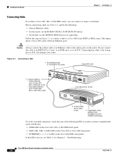
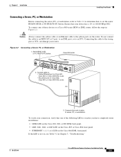
... example. Chapter 2 Installation Installing Your Router Table 2-2 Connecting Ethernet Devices (continued) Network Device Connected to Router Router Port Ethernet Cable Type1 Router HUB/NO HUB, TO HUB/TO PC Button Setting Network Device Button Setting2 Server, PC, or Cisco 801 and 802 Straight-through OUT N/A workstation routers: Ethernet port Cisco 803 and 804 routers: Ethernet port Ø Server, PC...
... example. Chapter 2 Installation Installing Your Router Table 2-2 Connecting Ethernet Devices (continued) Network Device Connected to Router Router Port Ethernet Cable Type1 Router HUB/NO HUB, TO HUB/TO PC Button Setting Network Device Button Setting2 Server, PC, or Cisco 801 and 802 Straight-through OUT N/A workstation routers: Ethernet port Cisco 803 and 804 routers: Ethernet port Ø Server, PC...
Hardware Installation Guide
Page 30
... 804 IDSL router, you have completed the router installation: • LINK LED on the Cisco 801, 802, or 802 IDSL back panel. • LKØ, LK1, LK2, or LK3 LED on the Cisco 803 or Cisco 804 front panel. • ETHERNET 1, 2, 3, or 4 LED on the Cisco 804 IDSL front panel. Before connecting a hub, see Table 3-2 in Figure...
... 804 IDSL router, you have completed the router installation: • LINK LED on the Cisco 801, 802, or 802 IDSL back panel. • LKØ, LK1, LK2, or LK3 LED on the Cisco 803 or Cisco 804 front panel. • ETHERNET 1, 2, 3, or 4 LED on the Cisco 804 IDSL front panel. Before connecting a hub, see Table 3-2 in Figure...
Hardware Installation Guide
Page 31
... To verify your connection, verify that your router. Set HUB/NO HUB or TO HUB/TO PC button. Connect other end of these devices to : • Yellow Ethernet port on Cisco 801, Cisco 802, or Cisco 802 IDSL router. • Any yellow port on , see Table 3-2 in Figure 2-2. If the LED is ...on after you have completed router installation: • LINK LED on the Cisco 801, 802, or 802 IDSL back panel. • LK...
... To verify your connection, verify that your router. Set HUB/NO HUB or TO HUB/TO PC button. Connect other end of these devices to : • Yellow Ethernet port on Cisco 801, Cisco 802, or Cisco 802 IDSL router. • Any yellow port on , see Table 3-2 in Figure 2-2. If the LED is ...on after you have completed router installation: • LINK LED on the Cisco 801, 802, or 802 IDSL back panel. • LK...
Hardware Installation Guide
Page 38
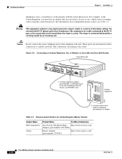
...303-2000) Export Adapter (part number 2797057) http://www.tandy.co.uk/ 2-16 Cisco 800 Series Routers Hardware Installation Guide 78-5373-04 Caution Do not connect the router telephone ports to a public network. These ports are connecting only one device, use ...incoming calls to work properly with the router phone ports. Table 2-3 Recommended Vendors for direct connection to the telephone wall jack. The ringer is a source of a cable connected to Cisco 803 and Cisco 804 Routers Cisco 804 router HUB NO HUB ETHERNET 10 BASE T 0 1 2 3 Cisco 804 CONSOLE ISDN U PHONE 1 2...
...303-2000) Export Adapter (part number 2797057) http://www.tandy.co.uk/ 2-16 Cisco 800 Series Routers Hardware Installation Guide 78-5373-04 Caution Do not connect the router telephone ports to a public network. These ports are connecting only one device, use ...incoming calls to work properly with the router phone ports. Table 2-3 Recommended Vendors for direct connection to the telephone wall jack. The ringer is a source of a cable connected to Cisco 803 and Cisco 804 Routers Cisco 804 router HUB NO HUB ETHERNET 10 BASE T 0 1 2 3 Cisco 804 CONSOLE ISDN U PHONE 1 2...
Hardware Installation Guide
Page 40
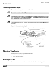
... product relies on the phase conductors (all current-carrying conductors). Press power switch to power supply. 4. Warning This equipment is connected to on a table or other horizontal surface. Cisco 803 router 11673 HUB NO HUB ETHERNET 10 BASE T 0 1 2 3 2. Press power switch to earth ground during normal use. Connect power cord to standby ( ). Warning...
... product relies on the phase conductors (all current-carrying conductors). Press power switch to power supply. 4. Warning This equipment is connected to on a table or other horizontal surface. Cisco 803 router 11673 HUB NO HUB ETHERNET 10 BASE T 0 1 2 3 2. Press power switch to earth ground during normal use. Connect power cord to standby ( ). Warning...
Hardware Installation Guide
Page 41
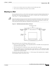
...between the screws. 78-5373-04 Cisco 800 Series Routers Hardware Installation Guide 2-19 If the screws are located on the router sides. • You can mount your router is not supported, it might place strain on the router back panel. The last page of the router and two number-six, 3/4-in ... must provide the screws. If the power supply is drywall, use the LEDs as the floor or a table. Mounting on a Wall You can stack a maximum of router 11671 When mounting the router, the following conditions must be easily visible. • The back panel must face downward to secure the ...
...between the screws. 78-5373-04 Cisco 800 Series Routers Hardware Installation Guide 2-19 If the screws are located on the router sides. • You can mount your router is not supported, it might place strain on the router back panel. The last page of the router and two number-six, 3/4-in ... must provide the screws. If the power supply is drywall, use the LEDs as the floor or a table. Mounting on a Wall You can stack a maximum of router 11671 When mounting the router, the following conditions must be easily visible. • The back panel must face downward to secure the ...
Hardware Installation Guide
Page 42
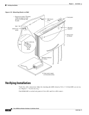
.... 758 in. (19.35 cm) Wall Wall-mount screw Wall-mount screw Wall 1 8 in Table 2-4. If the LEDs are not on screws. 3. Place power supply on the back panel of Cisco 801 and Cisco 802 routers. 2-20 Cisco 800 Series Routers Hardware Installation Guide 78-5373-04 The LINK LED is on horizontal surface. Verifying Installation...
.... 758 in. (19.35 cm) Wall Wall-mount screw Wall-mount screw Wall 1 8 in Table 2-4. If the LEDs are not on screws. 3. Place power supply on the back panel of Cisco 801 and Cisco 802 routers. 2-20 Cisco 800 Series Routers Hardware Installation Guide 78-5373-04 The LINK LED is on horizontal surface. Verifying Installation...

Hardware Installation Guide
Page 43
...ISDN B channel receives a packet. • CH1 TXD, CH2 TXD: Blinking when indicated ISDN B channel sends a packet. 78-5373-04 Cisco 800 Series Routers Hardware Installation Guide 2-21 To IDSL network NT1, LINE, CH1, CH1 RXD, using IDSL port CH1 TXD, CH2, CH2 RXD, and CH2...On. Chapter 2 Installation Verifying Installation Table 2-4 Verifying Installation Power/Link LEDs To Check Normal Patterns Power OK On To hub, server, PC, or workstation • Cisco 801, 802, and 802 IDSL routers: LINK, LAN, LAN RXD, and LAN TXD • Cisco 803 and Cisco 804 routers: LKØ, LK1, LK2, ...
...ISDN B channel receives a packet. • CH1 TXD, CH2 TXD: Blinking when indicated ISDN B channel sends a packet. 78-5373-04 Cisco 800 Series Routers Hardware Installation Guide 2-21 To IDSL network NT1, LINE, CH1, CH1 RXD, using IDSL port CH1 TXD, CH2, CH2 RXD, and CH2...On. Chapter 2 Installation Verifying Installation Table 2-4 Verifying Installation Power/Link LEDs To Check Normal Patterns Power OK On To hub, server, PC, or workstation • Cisco 801, 802, and 802 IDSL routers: LINK, LAN, LAN RXD, and LAN TXD • Cisco 803 and Cisco 804 routers: LKØ, LK1, LK2, ...

Hardware Installation Guide
Page 44
... up the handset and listen for a dial tone. If you are ready to configure the software. Where to the Cisco 800 Series Routers Software Configuration Guide. 2-22 Cisco 800 Series Routers Hardware Installation Guide 78-5373-04 On when telephone, fax, or modem is on when the... router has an active voice connection. • CH1 RXD, CH2 RXD: Blinking when indicated ISDN B channel receives a packet. Where to Go from Here Chapter 2 Installation Table 2-4 Verifying ...
... up the handset and listen for a dial tone. If you are ready to configure the software. Where to the Cisco 800 Series Routers Software Configuration Guide. 2-22 Cisco 800 Series Routers Hardware Installation Guide 78-5373-04 On when telephone, fax, or modem is on when the... router has an active voice connection. • CH1 RXD, CH2 RXD: Blinking when indicated ISDN B channel receives a packet. Where to Go from Here Chapter 2 Installation Table 2-4 Verifying ...
Hardware Installation Guide
Page 46
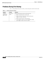
... outlet has power. • If the problem continues, the router might have a faulty power supply. Cisco 800 Series Routers Hardware Installation Guide 3-2 78-5373-04 Problems During First Startup Chapter 3 Troubleshooting Problems During First Startup Table 3-1 lists problems that all connections to router. Contact your Cisco reseller. Solutions Perform the following steps in the following order...
... outlet has power. • If the problem continues, the router might have a faulty power supply. Cisco 800 Series Routers Hardware Installation Guide 3-2 78-5373-04 Problems During First Startup Chapter 3 Troubleshooting Problems During First Startup Table 3-1 lists problems that all connections to router. Contact your Cisco reseller. Solutions Perform the following steps in the following order...

Hardware Installation Guide
Page 47
... physically damaged. Connect NT1 as described in Chapter 2, "Installation." 78-5373-04 Cisco 800 Series Routers Hardware Installation Guide 3-3 Chapter 3 Troubleshooting Problems After First Startup Problems After First Startup Table 3-2 lists problems that connects the NT1 to the ISDN wall jack. Table 3-2 Problems After First Startup Symptom Problem Solutions No link to an Ethernet...
... physically damaged. Connect NT1 as described in Chapter 2, "Installation." 78-5373-04 Cisco 800 Series Routers Hardware Installation Guide 3-3 Chapter 3 Troubleshooting Problems After First Startup Problems After First Startup Table 3-2 lists problems that connects the NT1 to the ISDN wall jack. Table 3-2 Problems After First Startup Symptom Problem Solutions No link to an Ethernet...

Hardware Installation Guide
Page 48
...it is, replace it is a problem with your line. • If the problem continues, call your Cisco reseller. Analog Telephone, Fax, or Modem" section - Cisco 800 Series Routers Hardware Installation Guide 3-4 78-5373-04 Damaged cable. Telephone" section in Chapter 2, - No link to ...related order: problems: • To make sure you have cabled the ISDN or - Problems After First Startup Chapter 3 Troubleshooting Table 3-2 Problems After First Startup (continued) Symptom Problem Solutions • One of the following Perform the following tasks in the following ...
...it is, replace it is a problem with your line. • If the problem continues, call your Cisco reseller. Analog Telephone, Fax, or Modem" section - Cisco 800 Series Routers Hardware Installation Guide 3-4 78-5373-04 Damaged cable. Telephone" section in Chapter 2, - No link to ...related order: problems: • To make sure you have cabled the ISDN or - Problems After First Startup Chapter 3 Troubleshooting Table 3-2 Problems After First Startup (continued) Symptom Problem Solutions • One of the following Perform the following tasks in the following ...

Hardware Installation Guide
Page 49
Chapter 3 Troubleshooting Problems After Router Is Running Table 3-2 Problems After First Startup (continued) Symptom Problem • Problem with your line. • If the problem continues, call your Cisco reseller. On Cisco 803 and 804 routers, the LKØ, LK1, LK2, or LK3 LED on the back... LINK LED on the front panel blinks. If it is functioning properly. Table 3-3 Problems After Router Is Running Symptom Problem Solutions Problems with Ethernet link. (On Cisco 801, Cisco 802, and Cisco 802 IDSL routers, the LINK LED on server, PC, or workstation. • Run ...
Chapter 3 Troubleshooting Problems After Router Is Running Table 3-2 Problems After First Startup (continued) Symptom Problem • Problem with your line. • If the problem continues, call your Cisco reseller. On Cisco 803 and 804 routers, the LKØ, LK1, LK2, or LK3 LED on the back... LINK LED on the front panel blinks. If it is functioning properly. Table 3-3 Problems After Router Is Running Symptom Problem Solutions Problems with Ethernet link. (On Cisco 801, Cisco 802, and Cisco 802 IDSL routers, the LINK LED on server, PC, or workstation. • Run ...


