Hardware Installation Guide
Page 3
... Requirements 1-5 Preparing for Installation 2-1 Overview 2-1 Installation Overview 2-1 Safety Recommendations 2-2 Maintaining Safety with Electricity 2-2 Preventing Electrostatic Discharge Damage 2-3 General Site Requirements 2-4 Site Environment 2-4 Preventive Site Configuration 2-4 Power Supply Considerations 2-4 Configuring Equipment Racks 2-6 Installing the Adaptive Security Appliance 3-1 Installing the Adaptive Security Appliance 3-1 Rack-Mounting the Chassis 3-2 Setting the Chassis on a Desktop 3-3 Connecting the...
... Requirements 1-5 Preparing for Installation 2-1 Overview 2-1 Installation Overview 2-1 Safety Recommendations 2-2 Maintaining Safety with Electricity 2-2 Preventing Electrostatic Discharge Damage 2-3 General Site Requirements 2-4 Site Environment 2-4 Preventive Site Configuration 2-4 Power Supply Considerations 2-4 Configuring Equipment Racks 2-6 Installing the Adaptive Security Appliance 3-1 Installing the Adaptive Security Appliance 3-1 Rack-Mounting the Chassis 3-2 Setting the Chassis on a Desktop 3-3 Connecting the...

Hardware Installation Guide
Page 4
... Working in an ESD Environment 4-3 Removing and Replacing a Lithium Battery in the SSM 4-4 Removing and Replacing the Power Supply 4-4 Removing the AC Power Supply 4-4 Replacing the AC Power Supply 4-6 Installing the DC Model 4-7 Removing and Replacing the CompactFlash 4-10 Removing the System CompactFlash 4-10 Replacing the System... 4-20 Installing and Replacing the AIP/CSC SSM 4-21 Installing the AIP/CSC SSM 4-21 Replacing the AIP/CSC SSM 4-22 Upgrading Memory for the Cisco ASA 5510 4-22 Removing the DIMM 4-23 Installing the DIMM 4-25 4-26 1 A P P E N D I X Cable Pinouts 1-1 10/100/1000BaseT...
... Working in an ESD Environment 4-3 Removing and Replacing a Lithium Battery in the SSM 4-4 Removing and Replacing the Power Supply 4-4 Removing the AC Power Supply 4-4 Replacing the AC Power Supply 4-6 Installing the DC Model 4-7 Removing and Replacing the CompactFlash 4-10 Removing the System CompactFlash 4-10 Replacing the System... 4-20 Installing and Replacing the AIP/CSC SSM 4-21 Installing the AIP/CSC SSM 4-21 Replacing the AIP/CSC SSM 4-22 Upgrading Memory for the Cisco ASA 5510 4-22 Removing the DIMM 4-23 Installing the DIMM 4-25 4-26 1 A P P E N D I X Cable Pinouts 1-1 10/100/1000BaseT...
Hardware Installation Guide
Page 6
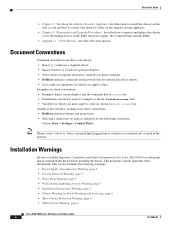
...: • Boldface indicates buttons and menu items. • Selecting a menu item (or pane) is indicated by the following warnings: • Power Supply Disconnection Warning, page 5 • Jewelry Removal Warning, page 5 • Wrist Strap Warning, page 5 • Work During Lightning Activity Warning,...screen displays and the command line in screen font. • Information you supply values. Installation Warnings Be sure to read the Regulatory Compliance and Safety Information for the Cisco ASA 5500 Series document that are entered literally as shown. • Italics indicate...
...: • Boldface indicates buttons and menu items. • Selecting a menu item (or pane) is indicated by the following warnings: • Power Supply Disconnection Warning, page 5 • Jewelry Removal Warning, page 5 • Wrist Strap Warning, page 5 • Work During Lightning Activity Warning,...screen displays and the command line in screen font. • Information you supply values. Installation Warnings Be sure to read the Regulatory Compliance and Safety Information for the Cisco ASA 5500 Series document that are entered literally as shown. • Italics indicate...

Hardware Installation Guide
Page 7
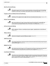
... Cisco ASA 5500 Series Hardware Installation Guide 5 Statement 1001 Installation Instructions Warning Warning Read the installation instructions before connecting the system to the card. disconnect the power at the circuit breaker on the system or connect or disconnect cables during periods of lightning activity. Statement 12 Jewelry Removal Warning Warning Before working near power supplies...
... Cisco ASA 5500 Series Hardware Installation Guide 5 Statement 1001 Installation Instructions Warning Warning Read the installation instructions before connecting the system to the card. disconnect the power at the circuit breaker on the system or connect or disconnect cables during periods of lightning activity. Statement 12 Jewelry Removal Warning Warning Before working near power supplies...
Hardware Installation Guide
Page 9
... Warning This product relies on the phase conductors (all current-carrying conductors). Statement 8 AC Power Disconnection Warning Warning Before working on a chassis or working near power supplies, unplug the power cord on AC units. Statement 13 78-17989-01 Cisco ASA 5500 Series Hardware Installation Guide 7 Install only in accordance with local and national electrical codes...
... Warning This product relies on the phase conductors (all current-carrying conductors). Statement 8 AC Power Disconnection Warning Warning Before working on a chassis or working near power supplies, unplug the power cord on AC units. Statement 13 78-17989-01 Cisco ASA 5500 Series Hardware Installation Guide 7 Install only in accordance with local and national electrical codes...
Hardware Installation Guide
Page 12
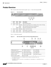
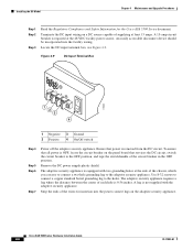
.... 3. GigabitEthernet interfaces, from right to left, GigabitEthernet 0/0, GigabitEthernet 0/1, GigabitEthernet 0/2, and GigabitEthernet 0/3. Figure 1-1 shows the front panel LEDs. Cisco ASA 5500 Series Hardware Installation Guide 1-2 OL-10089-01 Figure 1-2 Rear Panel LEDs and Ports (AC Power Supply Model Shown) 1 2 3 45 CONSOLE AUX MGMT USB2 USB1 119572 FLASH LINK SPD LINK SPD LINK SPD LINK SPD...
.... 3. GigabitEthernet interfaces, from right to left, GigabitEthernet 0/0, GigabitEthernet 0/1, GigabitEthernet 0/2, and GigabitEthernet 0/3. Figure 1-1 shows the front panel LEDs. Cisco ASA 5500 Series Hardware Installation Guide 1-2 OL-10089-01 Figure 1-2 Rear Panel LEDs and Ports (AC Power Supply Model Shown) 1 2 3 45 CONSOLE AUX MGMT USB2 USB1 119572 FLASH LINK SPD LINK SPD LINK SPD LINK SPD...

Hardware Installation Guide
Page 18
...Cisco ASA 5500 Series Hardware Installation Guide 2-2 78-17989-01 Statement 12 Follow these guidelines when working environment, so be alert and exercise good judgement at the circuit breaker on DC units. always check the circuit. The safety guidelines are working near power supplies, unplug the power cord on equipment powered...). Unpack the chassis. Place the chassis on a chassis or working . The list of the chassis, locate the emergency power-off the power. • Do not work alone if potentially hazardous conditions exist anywhere in your eyes. • Do not perform any...
...Cisco ASA 5500 Series Hardware Installation Guide 2-2 78-17989-01 Statement 12 Follow these guidelines when working environment, so be alert and exercise good judgement at the circuit breaker on DC units. always check the circuit. The safety guidelines are working near power supplies, unplug the power cord on equipment powered...). Unpack the chassis. Place the chassis on a chassis or working . The list of the chassis, locate the emergency power-off the power. • Do not work alone if potentially hazardous conditions exist anywhere in your eyes. • Do not perform any...
Hardware Installation Guide
Page 19
...an electrical accident occurs, proceed as listed in the Regulatory Compliance and Safety Information for the Cisco ASA 5500 Series document. • The adaptive security appliance models equipped with AC-input power supplies are shipped with a 3-wire electrical cord with the DC input wiring on a DC source... Compliance and Safety Information for the Cisco ASA 5500 Series document. Be sure to connect the grounding wire conduit to get medical aid. Connect the grounding clip to an unpainted surface of supplying at the 48 VDC facility power source. Ensure that it makes good...
...an electrical accident occurs, proceed as listed in the Regulatory Compliance and Safety Information for the Cisco ASA 5500 Series document. • The adaptive security appliance models equipped with AC-input power supplies are shipped with a 3-wire electrical cord with the DC input wiring on a DC source... Compliance and Safety Information for the Cisco ASA 5500 Series document. Be sure to connect the grounding wire conduit to get medical aid. Connect the grounding clip to an unpainted surface of supplying at the 48 VDC facility power source. Ensure that it makes good...
Hardware Installation Guide
Page 20
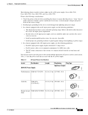
... cause immediate or intermittent equipment failure. • Ensure that the chassis top panel is secure. Power Supply Considerations For information on power supply considerations including environmental operating ranges and power requirements, see table 7 at the following topics: • Site Environment, page 2-4 •... damage to equipment. This section includes the following url: http://www.cisco.com/en/US/prod/collateral/vpndevc/ps6032/ps6094/ps6120/product_data_sheet0900a ecd802930c5.html Cisco ASA 5500 Series Hardware Installation Guide 2-4 78-17989-01 Damage from the ...
... cause immediate or intermittent equipment failure. • Ensure that the chassis top panel is secure. Power Supply Considerations For information on power supply considerations including environmental operating ranges and power requirements, see table 7 at the following topics: • Site Environment, page 2-4 •... damage to equipment. This section includes the following url: http://www.cisco.com/en/US/prod/collateral/vpndevc/ps6032/ps6094/ps6120/product_data_sheet0900a ecd802930c5.html Cisco ASA 5500 Series Hardware Installation Guide 2-4 78-17989-01 Damage from the ...
Hardware Installation Guide
Page 21
... system frame and chassis. The chassis does not have either an AC or DC power supply: Cisco ASA 5510, Cisco ASA 5520, Cisco ASA 5540, and Cisco ASA 5550. Each DC-input power supply requires dedicated 3-5 amp service. - Several styles of 14 AWG wire cable. - Table 2-1 lists the power cords that the power is to the label on the chassis for the correct AC-input...
... system frame and chassis. The chassis does not have either an AC or DC power supply: Cisco ASA 5510, Cisco ASA 5520, Cisco ASA 5540, and Cisco ASA 5550. Each DC-input power supply requires dedicated 3-5 amp service. - Several styles of 14 AWG wire cable. - Table 2-1 lists the power cords that the power is to the label on the chassis for the correct AC-input...
Hardware Installation Guide
Page 35
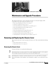
...Once the upgrade is complete, you can safely power on the chassis. 78-17989-01 Cisco ASA 5500 Series Hardware Installation Guide 4-1 Step 1 Step 2 Read the Regulatory Compliance and Safety Information for the Cisco ASA 5500 Series document. Upgrading the adaptive security appliance ... Working in an ESD Environment, page 4-3 • Removing and Replacing a Lithium Battery in the SSM, page 4-4 • Removing and Replacing the Power Supply, page 4-4 • Installing the DC Model, page 4-7 • Removing and Replacing the CompactFlash, page 4-10 • Installing and Replacing the ...
...Once the upgrade is complete, you can safely power on the chassis. 78-17989-01 Cisco ASA 5500 Series Hardware Installation Guide 4-1 Step 1 Step 2 Read the Regulatory Compliance and Safety Information for the Cisco ASA 5500 Series document. Upgrading the adaptive security appliance ... Working in an ESD Environment, page 4-3 • Removing and Replacing a Lithium Battery in the SSM, page 4-4 • Removing and Replacing the Power Supply, page 4-4 • Installing the DC Model, page 4-7 • Removing and Replacing the CompactFlash, page 4-10 • Installing and Replacing the ...
Hardware Installation Guide
Page 38
Cisco ASA 5500 Series Hardware Installation Guide 4-4 78-17989-01 Replace the chassis cover as described in "Installing and Replacing the Intelligent SSM" section on page 4-20. ... on page 2-4 This section describes how to remove and replace the power supply, and includes the following topics: • Removing the AC Power Supply, page 4-4 • Replacing the AC Power Supply, page 4-6 Removing the AC Power Supply To remove the AC power supply, perform the following url: http://www.cisco.com/en/US/prod/collateral/vpndevc/ps6032/ps6094/ps6120/product_data_sheet0900a ecd802930c5...
Cisco ASA 5500 Series Hardware Installation Guide 4-4 78-17989-01 Replace the chassis cover as described in "Installing and Replacing the Intelligent SSM" section on page 4-20. ... on page 2-4 This section describes how to remove and replace the power supply, and includes the following topics: • Removing the AC Power Supply, page 4-4 • Replacing the AC Power Supply, page 4-6 Removing the AC Power Supply To remove the AC power supply, perform the following url: http://www.cisco.com/en/US/prod/collateral/vpndevc/ps6032/ps6094/ps6120/product_data_sheet0900a ecd802930c5...
Hardware Installation Guide
Page 39
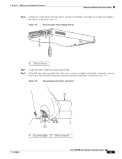
... to the chassis, as shown in Figure 4-5. Figure 4-5 Removing the Power Supply Screws FLASH POW ER STATUS ACTIVE VPN FLASH 119581 1 1 Chassis bottom Step 7 Step 8 Locate the power connector on the system board. Figure 4-6 Disconnecting the Power Connector 1 119639 2 1 AC power supply 2 Power connector 78-17989-01 Cisco ASA 5500 Series Hardware Installation Guide 4-5 Chapter 4 Maintenance and Upgrade Procedures...
... to the chassis, as shown in Figure 4-5. Figure 4-5 Removing the Power Supply Screws FLASH POW ER STATUS ACTIVE VPN FLASH 119581 1 1 Chassis bottom Step 7 Step 8 Locate the power connector on the system board. Figure 4-6 Disconnecting the Power Connector 1 119639 2 1 AC power supply 2 Power connector 78-17989-01 Cisco ASA 5500 Series Hardware Installation Guide 4-5 Chapter 4 Maintenance and Upgrade Procedures...

Hardware Installation Guide
Page 40
...Cisco ASA 5500 Series Hardware Installation Guide 4-6 78-17989-01 Removing and Replacing the Power Supply Chapter 4 Maintenance and Upgrade Procedures Step 9 Remove the power supply brace by pulling it up and out. Replacing the AC Power Supply To replace the AC power supply, perform the following steps: Step 1 Step 2 Insert the new power supply... security appliance. Figure 4-7 Removing the Power Supply 4 3 119578 2 1 1 Back panel 2 Power supply 3 Power supply brace 4 Front panel Step 10 From the back of the chassis, push the power supply forward, and then lift it towards ...
...Cisco ASA 5500 Series Hardware Installation Guide 4-6 78-17989-01 Removing and Replacing the Power Supply Chapter 4 Maintenance and Upgrade Procedures Step 9 Remove the power supply brace by pulling it up and out. Replacing the AC Power Supply To replace the AC power supply, perform the following steps: Step 1 Step 2 Insert the new power supply... security appliance. Figure 4-7 Removing the Power Supply 4 3 119578 2 1 1 Back panel 2 Power supply 3 Power supply brace 4 Front panel Step 10 From the back of the chassis, push the power supply forward, and then lift it towards ...
Hardware Installation Guide
Page 41
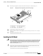
... OFF position. Figure 4-8 Replacing the Power Supply Brace and the AC Power Supply 4 3 119579 2 1 1 Back panel 2 Power supply 3 Power supply brace 4 Front panel Step 4 Step 5 Step 6 Connect the power connector to the system board. Statement ...7 Note The DC return connection should remain isolated from the DC circuit. Replace the adaptive adaptive security appliance cover. See "Replacing the Chassis Cover" for connection to the OFF position, and tape the switch handle of the following steps: 78-17989-01 Cisco ASA...
... OFF position. Figure 4-8 Replacing the Power Supply Brace and the AC Power Supply 4 3 119579 2 1 1 Back panel 2 Power supply 3 Power supply brace 4 Front panel Step 4 Step 5 Step 6 Connect the power connector to the system board. Statement ...7 Note The DC return connection should remain isolated from the DC circuit. Replace the adaptive adaptive security appliance cover. See "Replacing the Chassis Cover" for connection to the OFF position, and tape the switch handle of the following steps: 78-17989-01 Cisco ASA...
Hardware Installation Guide
Page 42
... DC circuit, switch the circuit breaker to the holes. Remove the DC power supply plastic shield. Use 8-32 screws to connect a copper standard barrel grounding lug to the OFF position, and tape the switch handle of the wires for the Cisco ASA 5500 Series document. Strip the ends of the circuit breaker in the...
... DC circuit, switch the circuit breaker to the holes. Remove the DC power supply plastic shield. Use 8-32 screws to connect a copper standard barrel grounding lug to the OFF position, and tape the switch handle of the wires for the Cisco ASA 5500 Series document. Strip the ends of the circuit breaker in the...

Hardware Installation Guide
Page 43
... 11 Step 12 After wiring the DC power supply, remove the tape from the circuit breaker switch handle and reinstate power by moving the handle of the chassis. Power on . 78-17989-01 Cisco ASA 5500 Series Hardware Installation Guide 4-9 Replace the DC power supply plastic shield. Note If you need to power cycle the DC adaptive security appliance...
... 11 Step 12 After wiring the DC power supply, remove the tape from the circuit breaker switch handle and reinstate power by moving the handle of the chassis. Power on . 78-17989-01 Cisco ASA 5500 Series Hardware Installation Guide 4-9 Replace the DC power supply plastic shield. Note If you need to power cycle the DC adaptive security appliance...

Hardware Installation Guide
Page 71
Numerics 1000 W power supplies power cords (table) 2-5 4GE SSM 4-15, 4-22 A AC-input power cords product numbers (table) 2-5 ASA replacing lithium battery 4-4 AUX port 1-2 C chassis covers removing 4-1 replacing 4-2 circuit breaker for DC unit 2-3 Cisco warranty 2-2 CompactFlash External 1-2, 1-3 Internal 4-10, 4-12 Console port 3-6 CPU 1-5 E electrostatic discharge see ... 4-8 I interface cables 3-4 4GE SSM 3-7 console port 3-6 management port 3-5 SSM 3-9 L LC connector 3-8 LEDs 1-4, 4-14, 4-21 M memory requirements 1-5 MGMT 1-2, 1-3, 3-5 Cisco ASA 5500 Series Hardware Installation Guide IN-1
Numerics 1000 W power supplies power cords (table) 2-5 4GE SSM 4-15, 4-22 A AC-input power cords product numbers (table) 2-5 ASA replacing lithium battery 4-4 AUX port 1-2 C chassis covers removing 4-1 replacing 4-2 circuit breaker for DC unit 2-3 Cisco warranty 2-2 CompactFlash External 1-2, 1-3 Internal 4-10, 4-12 Console port 3-6 CPU 1-5 E electrostatic discharge see ... 4-8 I interface cables 3-4 4GE SSM 3-7 console port 3-6 management port 3-5 SSM 3-9 L LC connector 3-8 LEDs 1-4, 4-14, 4-21 M memory requirements 1-5 MGMT 1-2, 1-3, 3-5 Cisco ASA 5500 Series Hardware Installation Guide IN-1

Hardware Installation Guide
Page 72
Index N Network interfaces 1-2 P panel removing 4-2 power LEDs 1-3, 1-4, 4-14, 4-21 power supplies considerations 2-4 product overview 1-2 R rear panels (figure) 1-4 RJ-45 connector pinouts 1-4 RJ-45 port 3-7 rubber feet attaching 3-3 S safety 2-2 Serial Console port 1-2, 1-3 SFP 3-7, 4-16 site environment 2-4 SSM 3-9, 4-4 4GE SSM connecting 3-7 installing 4-15, 4-22 LEDs 1-3, 4-14 replacing 4-16, 4-23 V ventilation fans 2-7 IN-2 Cisco ASA 5500 Series Hardware Installation Guide W warranty 2-2 78-17989-01
Index N Network interfaces 1-2 P panel removing 4-2 power LEDs 1-3, 1-4, 4-14, 4-21 power supplies considerations 2-4 product overview 1-2 R rear panels (figure) 1-4 RJ-45 connector pinouts 1-4 RJ-45 port 3-7 rubber feet attaching 3-3 S safety 2-2 Serial Console port 1-2, 1-3 SFP 3-7, 4-16 site environment 2-4 SSM 3-9, 4-4 4GE SSM connecting 3-7 installing 4-15, 4-22 LEDs 1-3, 4-14 replacing 4-16, 4-23 V ventilation fans 2-7 IN-2 Cisco ASA 5500 Series Hardware Installation Guide W warranty 2-2 78-17989-01

