Hardware Installation Guide
Page 3
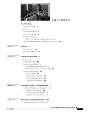
... Considerations 2-4 Configuring Equipment Racks 2-6 Installing the Adaptive Security Appliance 3-1 Installing the Adaptive Security Appliance 3-1 Rack-Mounting the Chassis 3-2 Setting the Chassis on a Desktop 3-3 Connecting the Interface Cables 3-4 Maintenance and Upgrade Procedures 4-1 Removing and Replacing the Chassis Cover 4-1 Cisco ASA 5500 Series Hardware Installation Guide 1
... Considerations 2-4 Configuring Equipment Racks 2-6 Installing the Adaptive Security Appliance 3-1 Installing the Adaptive Security Appliance 3-1 Rack-Mounting the Chassis 3-2 Setting the Chassis on a Desktop 3-3 Connecting the Interface Cables 3-4 Maintenance and Upgrade Procedures 4-1 Removing and Replacing the Chassis Cover 4-1 Cisco ASA 5500 Series Hardware Installation Guide 1
Hardware Installation Guide
Page 6
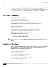
...interface examples uses these conventions: • Boldface indicates buttons and menu items. • Selecting a menu item (or pane) is shown in italic screen font. Note Means reader take note. Installation Warnings Be sure to read the Regulatory Compliance and Safety Information for the Cisco ASA... for Rack-Mounting and Servicing, page 6 • Short-Circuit Protection Warning, page 6 • SELV Circuit Warning, page 6 Cisco ASA 5500 Series Hardware Installation Guide 4 78-17989-01 This section includes the following convention: Choose Start > Settings > Control Panel. Examples...
...interface examples uses these conventions: • Boldface indicates buttons and menu items. • Selecting a menu item (or pane) is shown in italic screen font. Note Means reader take note. Installation Warnings Be sure to read the Regulatory Compliance and Safety Information for the Cisco ASA... for Rack-Mounting and Servicing, page 6 • Short-Circuit Protection Warning, page 6 • SELV Circuit Warning, page 6 Cisco ASA 5500 Series Hardware Installation Guide 4 78-17989-01 This section includes the following convention: Choose Start > Settings > Control Panel. Examples...
Hardware Installation Guide
Page 12
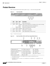
...Overview Product Overview This section describes the front and rear panels. Figure 1-1 Front Panel LEDs POWER STATUS ACTIVE VPN FLASH CISCO ASA 5540 SERIES Adaptive Security Appliance 119638 135 24 LED Color State Description 1 Power Green On The system has power. ...switch 9 Status indicator LED 14 Power connector 5 Power indicator LED 10 Active LED 1. Cisco ASA 5500 Series Hardware Installation Guide 1-2 OL-10089-01 The management 0/0 interface is a Fast Ethernet interface designed for management traffic only. 2. Figure 1-1 shows the front panel LEDs. Not ...
...Overview Product Overview This section describes the front and rear panels. Figure 1-1 Front Panel LEDs POWER STATUS ACTIVE VPN FLASH CISCO ASA 5540 SERIES Adaptive Security Appliance 119638 135 24 LED Color State Description 1 Power Green On The system has power. ...switch 9 Status indicator LED 14 Power connector 5 Power indicator LED 10 Active LED 1. Cisco ASA 5500 Series Hardware Installation Guide 1-2 OL-10089-01 The management 0/0 interface is a Fast Ethernet interface designed for management traffic only. 2. Figure 1-1 shows the front panel LEDs. Not ...

Hardware Installation Guide
Page 13
... port (labeled AUX on the chassis) is reserved for management traffic only. 4. Not supported at Cisco. Figure 1-3 2 Rear Panel LEDs and Ports for the Cisco ASA 5550 LED 2, 7 LINK Color State Green Solid Flashing Description There is a Fast Ethernet interface designed for internal use at this port to left, GigabitEthernet 1/0, GigabitEthernet 1/1, GigabitEthernet 1/2, and GigabitEthernet 1/3 Table...
... port (labeled AUX on the chassis) is reserved for management traffic only. 4. Not supported at Cisco. Figure 1-3 2 Rear Panel LEDs and Ports for the Cisco ASA 5550 LED 2, 7 LINK Color State Green Solid Flashing Description There is a Fast Ethernet interface designed for internal use at this port to left, GigabitEthernet 1/0, GigabitEthernet 1/1, GigabitEthernet 1/2, and GigabitEthernet 1/3 Table...

Hardware Installation Guide
Page 14
... Mbps 100 Mbps 1000 Mbps Note The Cisco ASA 5510 adaptive security appliance supports only 10/100BaseTX. Cisco ASA 5500 Series Hardware Installation Guide 1-4 OL-10089-01 Product Overview Chapter 1 Overview Table 1-1 4GE SSM LEDs (continued) for the Cisco ASA 5550 LED 3, 8 SPEED 4 POWER 5 ... LNK SPD 3 2 1 0 1 MGMT indicator LEDs 2 Network interface LEDs Table 1-2 lists the rear MGMT and Network interface LEDs. The system has power. The system diagnostics failed. The Cisco ASA 5520 and the Cisco ASA 5540 support 1000BaseT. Figure 1-4 shows the adaptive security appliance rear panel...
... Mbps 100 Mbps 1000 Mbps Note The Cisco ASA 5510 adaptive security appliance supports only 10/100BaseTX. Cisco ASA 5500 Series Hardware Installation Guide 1-4 OL-10089-01 Product Overview Chapter 1 Overview Table 1-1 4GE SSM LEDs (continued) for the Cisco ASA 5550 LED 3, 8 SPEED 4 POWER 5 ... LNK SPD 3 2 1 0 1 MGMT indicator LEDs 2 Network interface LEDs Table 1-2 lists the rear MGMT and Network interface LEDs. The system has power. The system diagnostics failed. The Cisco ASA 5520 and the Cisco ASA 5540 support 1000BaseT. Figure 1-4 shows the adaptive security appliance rear panel...

Hardware Installation Guide
Page 15
... of interfaces, and the same amount of RAM. For more information, see the Cisco Security Appliance Command Line Configuration Guide. Note The two units do not have to the unit with the larger Flash memory to have the same size Flash memory. Table 1-3 CPU and Memory Specifications ASA Model Cisco ASA 5510 Cisco ASA 5520 Cisco ASA 5540 Cisco ASA 5550 CPU...
... of interfaces, and the same amount of RAM. For more information, see the Cisco Security Appliance Command Line Configuration Guide. Note The two units do not have to the unit with the larger Flash memory to have the same size Flash memory. Table 1-3 CPU and Memory Specifications ASA Model Cisco ASA 5510 Cisco ASA 5520 Cisco ASA 5540 Cisco ASA 5550 CPU...

Hardware Installation Guide
Page 18
... items: documentation, a product CD, a power cord (AC models only), two RJ-45 Ethernet cables, one person to help ensure your Cisco warranty. Safety Recommendations Use the following sections to handle. Then, if an electrical accident occurs, you and others could fall over them. •...; Do not wear loose clothing or jewelry, such as additional memory or an interface card, doing so does not affect your safety and protect the adaptive security appliance. Cisco ASA 5500 Series Hardware Installation Guide 2-2 78-17989-01 Upgrading the adaptive security appliance does not...
... items: documentation, a product CD, a power cord (AC models only), two RJ-45 Ethernet cables, one person to help ensure your Cisco warranty. Safety Recommendations Use the following sections to handle. Then, if an electrical accident occurs, you and others could fall over them. •...; Do not wear loose clothing or jewelry, such as additional memory or an interface card, doing so does not affect your safety and protect the adaptive security appliance. Cisco ASA 5500 Series Hardware Installation Guide 2-2 78-17989-01 Upgrading the adaptive security appliance does not...

Hardware Installation Guide
Page 25
... opening). Statement 1006 The following topics: • Rack-Mounting the Chassis, page 3-2 • Setting the Chassis on a Desktop, page 3-3 • Connecting the Interface Cables, page 3-4 78-17989-01 Cisco ASA 5500 Series Hardware Installation Guide 3-1 Do not overcrowd an enclosed rack. You can help plan equipment rack installation: • Allow clearance around the...
... opening). Statement 1006 The following topics: • Rack-Mounting the Chassis, page 3-2 • Setting the Chassis on a Desktop, page 3-3 • Connecting the Interface Cables, page 3-4 78-17989-01 Cisco ASA 5500 Series Hardware Installation Guide 3-1 Do not overcrowd an enclosed rack. You can help plan equipment rack installation: • Allow clearance around the...

Hardware Installation Guide
Page 28
... Configuration Guide. Warning Only trained and qualified personnel should only be used for the Cisco ASA 5505 Adaptive Security Appliance and follow proper safety procedures when performing these steps. Cisco ASA 5500 Series Hardware Installation Guide 3-4 78-17989-01 Connect the interface cables. In this equipment. it should install, replace, or service this document, SSM...
... Configuration Guide. Warning Only trained and qualified personnel should only be used for the Cisco ASA 5505 Adaptive Security Appliance and follow proper safety procedures when performing these steps. Cisco ASA 5500 Series Hardware Installation Guide 3-4 78-17989-01 Connect the interface cables. In this equipment. it should install, replace, or service this document, SSM...

Hardware Installation Guide
Page 29
...as shown in a rack (if you are rack-mounting it.) Before connecting a computer or terminal to the ports, check to RJ-45 Ethernet cable Cisco ASA 5500 Series Hardware Installation Guide 3-5 Figure 3-5 1 Connecting to the Management Port MGMT USB2 USB1 92684 LNK SPD LNK SPD LNK SPD LNK SPD 3... Connect one RJ-45 connector to run the adaptive security appliance CLI. The port is a Fast Ethernet interface with a dedicated port used only for internal use at Cisco. therefore, customers cannot connect to this command, see the management-only command in shipping versions of the ...
...as shown in a rack (if you are rack-mounting it.) Before connecting a computer or terminal to the ports, check to RJ-45 Ethernet cable Cisco ASA 5500 Series Hardware Installation Guide 3-5 Figure 3-5 1 Connecting to the Management Port MGMT USB2 USB1 92684 LNK SPD LNK SPD LNK SPD LNK SPD 3... Connect one RJ-45 connector to run the adaptive security appliance CLI. The port is a Fast Ethernet interface with a dedicated port used only for internal use at Cisco. therefore, customers cannot connect to this command, see the management-only command in shipping versions of the ...

Hardware Installation Guide
Page 31
... only if you have installed the 4GE SSM on the adaptive security appliance. Use the media-type command in Figure 3-8. 78-17989-01 Cisco ASA 5500 Series Hardware Installation Guide 3-7 Insert and slide the SFP module into the port. - Connect the other end of the command syntax, see... • Ethernet port - Connect one RJ-45 connector to your network device, such as shown in interface configuration mode to set the media type to the RJ-45 port MMGGMMTT UUSSBB22 USB1 USB1 LNK 3 2 1 Cisco SSM-4GE 0 SPD 1 2 POWER STATUS 143147 1 Ethernet ports 2 RJ-45 connector Note When using...
... only if you have installed the 4GE SSM on the adaptive security appliance. Use the media-type command in Figure 3-8. 78-17989-01 Cisco ASA 5500 Series Hardware Installation Guide 3-7 Insert and slide the SFP module into the port. - Connect the other end of the command syntax, see... • Ethernet port - Connect one RJ-45 connector to your network device, such as shown in interface configuration mode to set the media type to the RJ-45 port MMGGMMTT UUSSBB22 USB1 USB1 LNK 3 2 1 Cisco SSM-4GE 0 SPD 1 2 POWER STATUS 143147 1 Ethernet ports 2 RJ-45 connector Note When using...

Hardware Installation Guide
Page 34
Figure 3-11 Connecting Cables to Network Interfaces MGMT USB2 USB1 92685 LNK SPD LNK SPD LNK SPD LNK SPD 3 2 1 0 1 2 1 RJ-45 Ethernet ports 2 RJ-45 connector Step 4 Step 5 Connect the power cord ... end to the Ethernet port. - Ethernet ports - For information on powering on a DC model, see the "Installing the DC Model" section on the chassis. 3-10 Cisco ASA 5500 Series Hardware Installation Guide 78-17989-01 Installing the Adaptive Security Appliance Chapter 3 Installing the Adaptive Security Appliance e.
Figure 3-11 Connecting Cables to Network Interfaces MGMT USB2 USB1 92685 LNK SPD LNK SPD LNK SPD LNK SPD 3 2 1 0 1 2 1 RJ-45 Ethernet ports 2 RJ-45 connector Step 4 Step 5 Connect the power cord ... end to the Ethernet port. - Ethernet ports - For information on powering on a DC model, see the "Installing the DC Model" section on the chassis. 3-10 Cisco ASA 5500 Series Hardware Installation Guide 78-17989-01 Installing the Adaptive Security Appliance Chapter 3 Installing the Adaptive Security Appliance e.

Hardware Installation Guide
Page 37
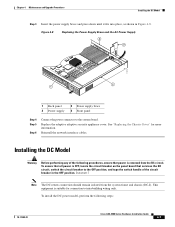
... Figure 4-3 Replacing the Chassis Cover 119637 POWER STATUSACTIVE VPN FLASH CISCO ASA 5540 SERIES Adaptive Security Appliance Step 4 Fasten the top panel with the chassis bottom. Step 6 Reinstall the network interface cables. Always follow ESD-prevention procedures when you set aside earlier ...as shown in Figure 4-3. Ensure that it makes good skin contact. CISCO ASA 5540 SERIES Adaptive Security Appliance Working in an ESD ...
... Figure 4-3 Replacing the Chassis Cover 119637 POWER STATUSACTIVE VPN FLASH CISCO ASA 5540 SERIES Adaptive Security Appliance Step 4 Fasten the top panel with the chassis bottom. Step 6 Reinstall the network interface cables. Always follow ESD-prevention procedures when you set aside earlier ...as shown in Figure 4-3. Ensure that it makes good skin contact. CISCO ASA 5540 SERIES Adaptive Security Appliance Working in an ESD ...
Hardware Installation Guide
Page 41
..."Replacing the Chassis Cover" for connection to the OFF position, and tape the switch handle of the following steps: 78-17989-01 Cisco ASA 5500 Series Hardware Installation Guide 4-7 To install the DC power model, perform the following procedures, ensure that power is OFF, locate ...for more information. To ensure that services the DC circuit, switch the circuit breaker to intra-building wiring only. Reinstall the network interface cables. Statement 7 Note The DC return connection should remain isolated from the DC circuit. Figure 4-8 Replacing the Power Supply Brace ...
..."Replacing the Chassis Cover" for connection to the OFF position, and tape the switch handle of the following steps: 78-17989-01 Cisco ASA 5500 Series Hardware Installation Guide 4-7 To install the DC power model, perform the following procedures, ensure that power is OFF, locate ...for more information. To ensure that services the DC circuit, switch the circuit breaker to intra-building wiring only. Reinstall the network interface cables. Statement 7 Note The DC return connection should remain isolated from the DC circuit. Figure 4-8 Replacing the Power Supply Brace ...

Hardware Installation Guide
Page 43
Note If you need to remain isolated from the system frame and chassis. Install any remaining interface boards as for the earth ground and tighten the screw on the adaptive security appliance from the circuit breaker switch handle and reinstate power .... Power on the connector. See Figure 4-10, and using the same method as described in "Installing the DC Model" section on . 78-17989-01 Cisco ASA 5500 Series Hardware Installation Guide 4-9 Chapter 4 Maintenance and Upgrade Procedures Installing the DC Model Step 8 Insert the ground wire into the connector for the ground...
Note If you need to remain isolated from the system frame and chassis. Install any remaining interface boards as for the earth ground and tighten the screw on the adaptive security appliance from the circuit breaker switch handle and reinstate power .... Power on the connector. See Figure 4-10, and using the same method as described in "Installing the DC Model" section on . 78-17989-01 Cisco ASA 5500 Series Hardware Installation Guide 4-9 Chapter 4 Maintenance and Upgrade Procedures Installing the DC Model Step 8 Insert the ground wire into the connector for the ground...

Hardware Installation Guide
Page 45
Step 10 Reinstall the network interface cables. 78-17989-01 Cisco ASA 5500 Series Hardware Installation Guide 4-11 Push the system CompactFlash inward until it is fully seated in the connector, see Figure 4-12. Figure 4-12 Replacing the System CompactFlash 1 114004 1 System CompactFlash Step 9 Replace the adaptive security appliance cover. Chapter 4 Maintenance and Upgrade Procedures Removing and Replacing the CompactFlash Step 7 Step 8 To install the system CompactFlash, align the new system CompactFlash with the connector on the riser card.
Step 10 Reinstall the network interface cables. 78-17989-01 Cisco ASA 5500 Series Hardware Installation Guide 4-11 Push the system CompactFlash inward until it is fully seated in the connector, see Figure 4-12. Figure 4-12 Replacing the System CompactFlash 1 114004 1 System CompactFlash Step 9 Replace the adaptive security appliance cover. Chapter 4 Maintenance and Upgrade Procedures Removing and Replacing the CompactFlash Step 7 Step 8 To install the system CompactFlash, align the new system CompactFlash with the connector on the riser card.

Hardware Installation Guide
Page 48
... slots. For a complete description of the command syntax, see the "Installing and Removing the SFP Modules" section on SFP ports and modules, see the Cisco ASA 5500 Series Command Reference. You must order and install the SFP modules if you can use this feature. Installing and Replacing the 4GE SSM Chapter.../1000 Mbps, copper, RJ-45 ports and four optional 1000 Mbps, Small-Form-Factor Pluggable (SFP) fiber ports. Use the media-type command in interface configuration mode to set the media type to use the same numbered copper ports (RJ-45) and the SFP ports at the same time.
... slots. For a complete description of the command syntax, see the "Installing and Removing the SFP Modules" section on SFP ports and modules, see the Cisco ASA 5500 Series Command Reference. You must order and install the SFP modules if you can use this feature. Installing and Replacing the 4GE SSM Chapter.../1000 Mbps, copper, RJ-45 ports and four optional 1000 Mbps, Small-Form-Factor Pluggable (SFP) fiber ports. Use the media-type command in interface configuration mode to set the media type to use the same numbered copper ports (RJ-45) and the SFP ports at the same time.

Hardware Installation Guide
Page 63
... Mon 16-April-07 03:29 by root 78-17989-01 Cisco ASA 5500 Series Hardware Installation Guide 4-29 Reinstall the network interface cables. Step 5 Step 6 When you finish installing the DIMM, replace the adaptive security appliance cover. Verifying the Memory Upgrade Cisco ASA 5510 You can verify that the memory upgrade has been completed...
... Mon 16-April-07 03:29 by root 78-17989-01 Cisco ASA 5500 Series Hardware Installation Guide 4-29 Reinstall the network interface cables. Step 5 Step 6 When you finish installing the DIMM, replace the adaptive security appliance cover. Verifying the Memory Upgrade Cisco ASA 5510 You can verify that the memory upgrade has been completed...

Hardware Installation Guide
Page 71
... 4-15, 4-22 A AC-input power cords product numbers (table) 2-5 ASA replacing lithium battery 4-4 AUX port 1-2 C chassis covers removing 4-1 replacing 4-2 circuit breaker for DC unit 2-3 Cisco warranty 2-2 CompactFlash External 1-2, 1-3 Internal 4-10, 4-12 Console port 3-6 ...CPU 1-5 E electrostatic discharge see ESD equipment racks tips 2-7 78-17989-01 INDEX ESD preventing 2-3, 4-3 F failover 1-5, 3-4 fans ventilation 2-7 G grounding lug attaching 4-8 I interface cables 3-4 4GE SSM 3-7...
... 4-15, 4-22 A AC-input power cords product numbers (table) 2-5 ASA replacing lithium battery 4-4 AUX port 1-2 C chassis covers removing 4-1 replacing 4-2 circuit breaker for DC unit 2-3 Cisco warranty 2-2 CompactFlash External 1-2, 1-3 Internal 4-10, 4-12 Console port 3-6 ...CPU 1-5 E electrostatic discharge see ESD equipment racks tips 2-7 78-17989-01 INDEX ESD preventing 2-3, 4-3 F failover 1-5, 3-4 fans ventilation 2-7 G grounding lug attaching 4-8 I interface cables 3-4 4GE SSM 3-7...

Hardware Installation Guide
Page 72
Index N Network interfaces 1-2 P panel removing 4-2 power LEDs 1-3, 1-4, 4-14, 4-21 power supplies considerations 2-4 product overview 1-2 R rear panels (figure) 1-4 RJ-45 connector pinouts 1-4 RJ-45 port 3-7 rubber feet attaching 3-3 S safety 2-2 Serial Console port 1-2, 1-3 SFP 3-7, 4-16 site environment 2-4 SSM 3-9, 4-4 4GE SSM connecting 3-7 installing 4-15, 4-22 LEDs 1-3, 4-14 replacing 4-16, 4-23 V ventilation fans 2-7 IN-2 Cisco ASA 5500 Series Hardware Installation Guide W warranty 2-2 78-17989-01
Index N Network interfaces 1-2 P panel removing 4-2 power LEDs 1-3, 1-4, 4-14, 4-21 power supplies considerations 2-4 product overview 1-2 R rear panels (figure) 1-4 RJ-45 connector pinouts 1-4 RJ-45 port 3-7 rubber feet attaching 3-3 S safety 2-2 Serial Console port 1-2, 1-3 SFP 3-7, 4-16 site environment 2-4 SSM 3-9, 4-4 4GE SSM connecting 3-7 installing 4-15, 4-22 LEDs 1-3, 4-14 replacing 4-16, 4-23 V ventilation fans 2-7 IN-2 Cisco ASA 5500 Series Hardware Installation Guide W warranty 2-2 78-17989-01