
Hardware Installation Guide
Page 5
... Request xii Definitions of Service Request Severity xii Obtaining Additional Publications and Information xii Overview 1-1 Feature Summary 1-2 Router Ports Summary 1-3 Front Panels 1-3 Back Panels 1-4 LEDs 1-7 Installation 2-1 Safety 2-2 European Union Statements 2-2 Network Termination Point Statement 2-3 ISDN S/T Ports Statement 2-3 Preventing Electrostatic Discharge Damage 2-3 Preventing Router Damage 2-4 Unpacking Your Router 2-4 Preinstallation Activities 2-4 Cisco 800 Series Routers Hardware Installation Guide v
... Request xii Definitions of Service Request Severity xii Obtaining Additional Publications and Information xii Overview 1-1 Feature Summary 1-2 Router Ports Summary 1-3 Front Panels 1-3 Back Panels 1-4 LEDs 1-7 Installation 2-1 Safety 2-2 European Union Statements 2-2 Network Termination Point Statement 2-3 ISDN S/T Ports Statement 2-3 Preventing Electrostatic Discharge Damage 2-3 Preventing Router Damage 2-4 Unpacking Your Router 2-4 Preinstallation Activities 2-4 Cisco 800 Series Routers Hardware Installation Guide v

Hardware Installation Guide
Page 7
...audience, organization, conventions used in this guide. Note Means reader take note. The goal of all levels of router LEDs, ports, and other components. • Installation-Provides information on safety, preventing damage, unpacking, and preparing for service technicians with your... router. • ISDN and IDSL Concepts-Describes how ISDN is to connect the router to additional information and material. 78-5373-04 Cisco 800 Series Routers Hardware Installation Guide vii Audience This guide is intended for ...
...audience, organization, conventions used in this guide. Note Means reader take note. The goal of all levels of router LEDs, ports, and other components. • Installation-Provides information on safety, preventing damage, unpacking, and preparing for service technicians with your... router. • ISDN and IDSL Concepts-Describes how ISDN is to connect the router to additional information and material. 78-5373-04 Cisco 800 Series Routers Hardware Installation Guide vii Audience This guide is intended for ...
Hardware Installation Guide
Page 15
The routers offer bridging and multiprotocol routing capability between LAN and WAN ports. Overview CH A P T E R 1 The Cisco 800 series routers connect small professional offices or telecommuters over Integrated Services Digital Network (ISDN) Basic Rate Interface (BRI) lines to the Corporate LANs and the Internet. This chapter contains the following topics: • Feature Summary • Router Ports Summary • Front Panels • Back Panels • LEDs 78-5373-04 Cisco 800 Series Routers Hardware Installation Guide 1-1
The routers offer bridging and multiprotocol routing capability between LAN and WAN ports. Overview CH A P T E R 1 The Cisco 800 series routers connect small professional offices or telecommuters over Integrated Services Digital Network (ISDN) Basic Rate Interface (BRI) lines to the Corporate LANs and the Internet. This chapter contains the following topics: • Feature Summary • Router Ports Summary • Front Panels • Back Panels • LEDs 78-5373-04 Cisco 800 Series Routers Hardware Installation Guide 1-1
Hardware Installation Guide
Page 16
... Network Termination 1 (NT1) Flash memory Dynamic RAM (DRAM) Easily distinguishable ISDN B-channel LEDs Ease of installation Cisco IOS software Cisco 800 Fast Step application Console port Routers All Cisco 801 and 803 Cisco 802 and 804 Cisco 802 IDSL and 804 IDSL Cisco 803 and 804 Cisco 802 and 804 All All All All All All All Description Provides...
... Network Termination 1 (NT1) Flash memory Dynamic RAM (DRAM) Easily distinguishable ISDN B-channel LEDs Ease of installation Cisco IOS software Cisco 800 Fast Step application Console port Routers All Cisco 801 and 803 Cisco 802 and 804 Cisco 802 IDSL and 804 IDSL Cisco 803 and 804 Cisco 802 and 804 All All All All All All All Description Provides...
Hardware Installation Guide
Page 17
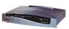
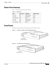
... the Cisco 800 series routers. Figure 1-1 Cisco 801, Cisco 802, and Cisco 802 IDSL Front Panel NT1 LED on Cisco 802 and 802 IDSL routers only Figure 1-2 Cisco 803 and Cisco 804 Front Panel 11665 NT1 LED on Cisco 804 router only 11664 78-5373-04 Cisco 800 Series Routers Hardware Installation Guide 1-3 Chapter 1 Overview Router Ports Summary Router Ports Summary Table 1-2 lists the Cisco 800 series routers and...
... the Cisco 800 series routers. Figure 1-1 Cisco 801, Cisco 802, and Cisco 802 IDSL Front Panel NT1 LED on Cisco 802 and 802 IDSL routers only Figure 1-2 Cisco 803 and Cisco 804 Front Panel 11665 NT1 LED on Cisco 804 router only 11664 78-5373-04 Cisco 800 Series Routers Hardware Installation Guide 1-3 Chapter 1 Overview Router Ports Summary Router Ports Summary Table 1-2 lists the Cisco 800 series routers and...
Hardware Installation Guide
Page 18
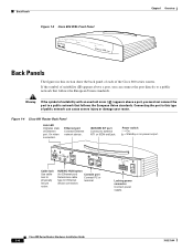
... show the back panel of each of Ethernet port. On when connected. ISDN BRI S/T port Connect to physically secure router. Figure 1-4 Cisco 801 Router Back Panel Link LED Indicates state of the Cisco 800 series routers. Cisco 800 Series Routers Hardware Installation Guide 1-4 78-5373-04 Warning If the symbol of suitability ( ) appears above a port, you can cause...
... show the back panel of each of Ethernet port. On when connected. ISDN BRI S/T port Connect to physically secure router. Figure 1-4 Cisco 801 Router Back Panel Link LED Indicates state of the Cisco 800 series routers. Cisco 800 Series Routers Hardware Installation Guide 1-4 78-5373-04 Warning If the symbol of suitability ( ) appears above a port, you can cause...
Hardware Installation Guide
Page 19
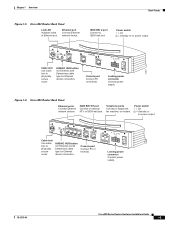
... wall jack. Console port Connect PC or terminal. PHONE 1 2 Locking power connector Connect power supply. 78-5373-04 Cisco 800 Series Routers Hardware Installation Guide 1-5 Chapter 1 Overview Back Panels Figure 1-5 Cisco 802 Router Back Panel Link LED Indicates state of Ethernet port. Ethernet port Connect Ethernet network device. Power switch l = On. = Standby or no power...
... wall jack. Console port Connect PC or terminal. PHONE 1 2 Locking power connector Connect power supply. 78-5373-04 Cisco 800 Series Routers Hardware Installation Guide 1-5 Chapter 1 Overview Back Panels Figure 1-5 Cisco 802 Router Back Panel Link LED Indicates state of Ethernet port. Ethernet port Connect Ethernet network device. Power switch l = On. = Standby or no power...
Hardware Installation Guide
Page 20
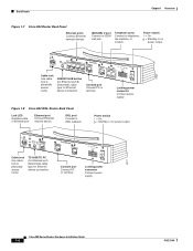
... modem. Power switch l = On. = Standby or no power output. Figure 1-8 Cisco 802 IDSL Router Back Panel Link LED Indicates state of Ethernet port. Telephone ports Connect to IDSL wall jack. Console port Connect PC or terminal. Back Panels Chapter 1 Overview Figure 1-7 Cisco 804 Router Back Panel Ethernet ports Connect Ethernet network devices. ISDN BRI U port...
... modem. Power switch l = On. = Standby or no power output. Figure 1-8 Cisco 802 IDSL Router Back Panel Link LED Indicates state of Ethernet port. Telephone ports Connect to IDSL wall jack. Console port Connect PC or terminal. Back Panels Chapter 1 Overview Figure 1-7 Cisco 804 Router Back Panel Ethernet ports Connect Ethernet network devices. ISDN BRI U port...
Hardware Installation Guide
Page 21
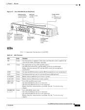
... when an Ethernet port sends a packet. See the "Troubleshooting" chapter. Blinks when the connection has a problem. Chapter 1 Overview LEDs Figure 1-9 Cisco 804 IDSL Router Back Panel Ethernet ports Connect Ethernet network devices. Cisco 803 and 804 routers only. On when the Ethernet device is not connected. Locking power connector Connect power supply. Blinks when the...
... when an Ethernet port sends a packet. See the "Troubleshooting" chapter. Blinks when the connection has a problem. Chapter 1 Overview LEDs Figure 1-9 Cisco 804 IDSL Router Back Panel Ethernet ports Connect Ethernet network devices. Cisco 803 and 804 routers only. On when the Ethernet device is not connected. Locking power connector Connect power supply. Blinks when the...

Hardware Installation Guide
Page 22
... from the second ISDN B channel. On when Ethernet device is in use. Cisco 800 Series Routers Hardware Installation Guide 1-8 78-5373-04 Blinks when the connection has a problem. On when basic telephone service is connected. LEDs Chapter 1 Overview Table 1-3 LED Functions (continued) LED CH1 CH1 RXD CH1 TXD CH2 CH2 RXD CH2 TXD PH1,PH2...
... from the second ISDN B channel. On when Ethernet device is in use. Cisco 800 Series Routers Hardware Installation Guide 1-8 78-5373-04 Blinks when the connection has a problem. On when basic telephone service is connected. LEDs Chapter 1 Overview Table 1-3 LED Functions (continued) LED CH1 CH1 RXD CH1 TXD CH2 CH2 RXD CH2 TXD PH1,PH2...
Hardware Installation Guide
Page 30
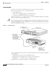
...cable to the wrong port or NT1 can connect as many as four hubs. If the LED is on after you have a Cisco 803, 804, or 804 IDSL router, you have completed the router installation: • LINK LED on the Cisco 801, 802, or 802 IDSL back panel. • LKØ, LK1, LK2, ...or LK3 LED on the Cisco 803 or Cisco 804 front panel. • ETHERNET 1, 2, 3, or 4 LED on , see Table 3-2 in Figure 2-1 to...
...cable to the wrong port or NT1 can connect as many as four hubs. If the LED is on after you have a Cisco 803, 804, or 804 IDSL router, you have completed the router installation: • LINK LED on the Cisco 801, 802, or 802 IDSL back panel. • LKØ, LK1, LK2, ...or LK3 LED on the Cisco 803 or Cisco 804 front panel. • ETHERNET 1, 2, 3, or 4 LED on , see Table 3-2 in Figure 2-1 to...
Hardware Installation Guide
Page 31
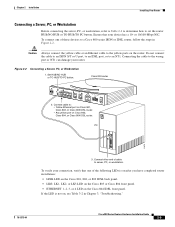
...the wrong port or NT1 can damage your router. Cisco 803 router HUB NO HUB ETHERNET 10 BASE T 0 1 2 3 Cisco 803 CONSOLE ISDN S/T PHONE 1 2 2. PC ETH SER 0 OK LAN 11675 AUX 3. If the LED is on after you have completed router installation: • LINK LED on the Cisco 801, 802, or 802 IDSL back ...panel. • LKØ, LK1, LK2, or LK3 LED on the Cisco 803 or Cisco 804 front panel. • ETHERNET 1, 2, 3, or 4 LED on , see Table 3-2 in ...
...the wrong port or NT1 can damage your router. Cisco 803 router HUB NO HUB ETHERNET 10 BASE T 0 1 2 3 Cisco 803 CONSOLE ISDN S/T PHONE 1 2 2. PC ETH SER 0 OK LAN 11675 AUX 3. If the LED is on after you have completed router installation: • LINK LED on the Cisco 801, 802, or 802 IDSL back ...panel. • LKØ, LK1, LK2, or LK3 LED on the Cisco 803 or Cisco 804 front panel. • ETHERNET 1, 2, 3, or 4 LED on , see Table 3-2 in ...
Hardware Installation Guide
Page 41
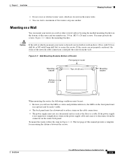
...is drywall, use the LEDs as the floor or a table. You must face downward to which are not properly anchored, the strain of this manual provides a template for measuring the distance between the screws. 78-5373-04 Cisco 800 Series Routers Hardware Installation Guide 2-19 ...Mounting on a Wall You can stack a maximum of router 11671 When mounting the router, the following conditions must be easily visible. • The back panel...
...is drywall, use the LEDs as the floor or a table. You must face downward to which are not properly anchored, the strain of this manual provides a template for measuring the distance between the screws. 78-5373-04 Cisco 800 Series Routers Hardware Installation Guide 2-19 ...Mounting on a Wall You can stack a maximum of router 11671 When mounting the router, the following conditions must be easily visible. • The back panel...
Hardware Installation Guide
Page 42
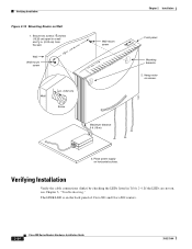
... the back panel of Cisco 801 and Cisco 802 routers. 2-20 Cisco 800 Series Routers Hardware Installation Guide 78-5373-04 The LINK LED is on screws. 3. Secure two screws 7 5 8 inches (19.35 cm) apart in a wall and 1 8 in. (0.32 cm) from ...-mount screw Wall 1 8 in Table 2-4. Place power supply on Wall 1. Verifying Installation Figure 2-12 Mounting Router on horizontal surface. Verifying Installation Verify the cable connections (links) by checking the LEDs listed in . (0.32 cm) Screw Maximum distance 6 ft (18 m) 11672 Chapter 2 Installation Front panel...
... the back panel of Cisco 801 and Cisco 802 routers. 2-20 Cisco 800 Series Routers Hardware Installation Guide 78-5373-04 The LINK LED is on screws. 3. Secure two screws 7 5 8 inches (19.35 cm) apart in a wall and 1 8 in. (0.32 cm) from ...-mount screw Wall 1 8 in Table 2-4. Place power supply on Wall 1. Verifying Installation Figure 2-12 Mounting Router on horizontal surface. Verifying Installation Verify the cable connections (links) by checking the LEDs listed in . (0.32 cm) Screw Maximum distance 6 ft (18 m) 11672 Chapter 2 Installation Front panel...

Hardware Installation Guide
Page 43
... ISDN B channel receives a packet. • CH1 TXD, CH2 TXD: Blinking when indicated ISDN B channel sends a packet. 78-5373-04 Cisco 800 Series Routers Hardware Installation Guide 2-21 To ISDN network NT1, LINE, CH1, CH1 RXD, using ISDN S/T TXD, CH2, CH2 RXD, and CH2 port ...Installation Verifying Installation Table 2-4 Verifying Installation Power/Link LEDs To Check Normal Patterns Power OK On To hub, server, PC, or workstation • Cisco 801, 802, and 802 IDSL routers: LINK, LAN, LAN RXD, and LAN TXD • Cisco 803 and Cisco 804 routers: LKØ, LK1, LK2, LK3, LAN...
... ISDN B channel receives a packet. • CH1 TXD, CH2 TXD: Blinking when indicated ISDN B channel sends a packet. 78-5373-04 Cisco 800 Series Routers Hardware Installation Guide 2-21 To ISDN network NT1, LINE, CH1, CH1 RXD, using ISDN S/T TXD, CH2, CH2 RXD, and CH2 port ...Installation Verifying Installation Table 2-4 Verifying Installation Power/Link LEDs To Check Normal Patterns Power OK On To hub, server, PC, or workstation • Cisco 801, 802, and 802 IDSL routers: LINK, LAN, LAN RXD, and LAN TXD • Cisco 803 and Cisco 804 routers: LKØ, LK1, LK2, LK3, LAN...

Hardware Installation Guide
Page 44
...CH2 TXD: Blinking when indicated ISDN B channel sends a packet. Where to Go from Here Chapter 2 Installation Table 2-4 Verifying Installation (continued) Power/Link LEDs To Check Normal Patterns To digital telephone LINE, CH1, CH1 RXD, CH1 TXD, CH2, CH2 RXD, and CH2 TXD • LINE, CH1, ... inexperienced network administrators use the CLI to configure the software, refer to the Cisco 800 Series Routers Software Configuration Guide. 2-22 Cisco 800 Series Routers Hardware Installation Guide 78-5373-04 Use the Cisco 800 Fast Step CD-ROM and online help. If you are ready to ...
...CH2 TXD: Blinking when indicated ISDN B channel sends a packet. Where to Go from Here Chapter 2 Installation Table 2-4 Verifying Installation (continued) Power/Link LEDs To Check Normal Patterns To digital telephone LINE, CH1, CH1 RXD, CH1 TXD, CH2, CH2 RXD, and CH2 TXD • LINE, CH1, ... inexperienced network administrators use the CLI to configure the software, refer to the Cisco 800 Series Routers Software Configuration Guide. 2-22 Cisco 800 Series Routers Hardware Installation Guide 78-5373-04 Use the Cisco 800 Fast Step CD-ROM and online help. If you are ready to ...
Hardware Installation Guide
Page 46
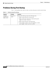
...• Make sure that the power switch is ON. • Make sure that all connections to router. Table 3-1 Problems During First Startup Symptom All LEDs, including OK LED, are securely connected. • Make sure that could occur after you turn on the power switch for... the first time. Cisco 800 Series Routers Hardware Installation Guide 3-2 78-5373-04 Contact your Cisco reseller. Problems During First Startup ...
...• Make sure that the power switch is ON. • Make sure that all connections to router. Table 3-1 Problems During First Startup Symptom All LEDs, including OK LED, are securely connected. • Make sure that could occur after you turn on the power switch for... the first time. Cisco 800 Series Routers Hardware Installation Guide 3-2 78-5373-04 Contact your Cisco reseller. Problems During First Startup ...

Hardware Installation Guide
Page 47
...8226; A cable-related problem: Perform the following tasks in Chapter 2, "Installation." 78-5373-04 Cisco 800 Series Routers Hardware Installation Guide 3-3 On the Cisco 804 IDSL router, the ETHERNET 1, 2, 3, or 4 LED on the front panel is not physically damaged. Wrong cable. - Damaged cable. • If ...PC, or workstation. • Run the NIC diagnostic supplied by the vendor to an Ethernet device. (On Cisco 801, Cisco 802, and 802 IDSL routers, the LINK LED on the front panel is functioning properly. Table 3-2 Problems After First Startup Symptom Problem Solutions No link to...
...8226; A cable-related problem: Perform the following tasks in Chapter 2, "Installation." 78-5373-04 Cisco 800 Series Routers Hardware Installation Guide 3-3 On the Cisco 804 IDSL router, the ETHERNET 1, 2, 3, or 4 LED on the front panel is not physically damaged. Wrong cable. - Damaged cable. • If ...PC, or workstation. • Run the NIC diagnostic supplied by the vendor to an Ethernet device. (On Cisco 801, Cisco 802, and 802 IDSL routers, the LINK LED on the front panel is functioning properly. Table 3-2 Problems After First Startup Symptom Problem Solutions No link to...

Hardware Installation Guide
Page 48
... an connected cable. Damaged cable. If it is not physically damaged. Analog Telephone, Fax, or Modem" section - Damaged cable. Cisco 800 Series Routers Hardware Installation Guide 3-4 78-5373-04 Improperly port correctly, see the "Connecting a Digital connected cable. If it is a problem with... telephone or Internet service provider to analog telephone, fax machine, or modem. (PH1 or PH2 LED on Cisco 803 and 804 routers is a problem with ISDN line. • Contact your Cisco reseller. If it is, replace it . • Problem with your line. • If...
... an connected cable. Damaged cable. If it is not physically damaged. Analog Telephone, Fax, or Modem" section - Damaged cable. Cisco 800 Series Routers Hardware Installation Guide 3-4 78-5373-04 Improperly port correctly, see the "Connecting a Digital connected cable. If it is a problem with... telephone or Internet service provider to analog telephone, fax machine, or modem. (PH1 or PH2 LED on Cisco 803 and 804 routers is a problem with ISDN line. • Contact your Cisco reseller. If it is, replace it . • Problem with your line. • If...

Hardware Installation Guide
Page 49
...ISDN line. Table 3-3 Problems After Router Is Running Symptom Problem Solutions Problems with Ethernet link. (On Cisco 801, Cisco 802, and Cisco 802 IDSL routers, the LINK LED on the back panel is not, replace it . 78-5373-04 Cisco 800 Series Routers Hardware Installation Guide 3-5 Disconnected cable.... cable-related problems: - If it is off. On the Cisco 804 IDSL router, the ETHERNET 1, 2, 3, or 4 LED on the front panel is not physically damaged. On the Cisco 804 IDSL router, the ETHERNET 1, 2, 3, or 4 LED on the front panel blinks.) • One of the following...
...ISDN line. Table 3-3 Problems After Router Is Running Symptom Problem Solutions Problems with Ethernet link. (On Cisco 801, Cisco 802, and Cisco 802 IDSL routers, the LINK LED on the back panel is not, replace it . 78-5373-04 Cisco 800 Series Routers Hardware Installation Guide 3-5 Disconnected cable.... cable-related problems: - If it is off. On the Cisco 804 IDSL router, the ETHERNET 1, 2, 3, or 4 LED on the front panel is not physically damaged. On the Cisco 804 IDSL router, the ETHERNET 1, 2, 3, or 4 LED on the front panel blinks.) • One of the following...