
Installation Guide
Page 4
... Port 2-42 Connecting to 100BASE-FX Ports 2-43 Connecting the Switch to the Power Converter 2-44 Attaching the Power Converter to the Switch 2-45 Installing the Power Converter on a DIN Rail, Wall, or Rack Adapter 2-46 Connecting the DC Power Clip 2-46 Connecting the Power Converter to an AC Power Source 2-47 Cisco IE 3000 Switch Hardware Installation Guide iv OL-13017-01
... Port 2-42 Connecting to 100BASE-FX Ports 2-43 Connecting the Switch to the Power Converter 2-44 Attaching the Power Converter to the Switch 2-45 Installing the Power Converter on a DIN Rail, Wall, or Rack Adapter 2-46 Connecting the DC Power Clip 2-46 Connecting the Power Converter to an AC Power Source 2-47 Cisco IE 3000 Switch Hardware Installation Guide iv OL-13017-01
Installation Guide
Page 6
... a DIN Rail, Wall, or Rack Adapter B-52 Connecting the DC Power Clip B-52 Connecting the Power Converter to an AC Power Source B-53 Preparing the AC Power Cord B-53 Connecting the AC Power Cord to the Power Converter B-54 Connecting the Power Converter to a DC Power Source B-57 Applying Power to the Power Converter B-59 Cisco IE 3000 Switch Hardware Installation Guide vi OL-13017-01
... a DIN Rail, Wall, or Rack Adapter B-52 Connecting the DC Power Clip B-52 Connecting the Power Converter to an AC Power Source B-53 Preparing the AC Power Cord B-53 Connecting the AC Power Cord to the Power Converter B-54 Connecting the Power Converter to a DC Power Source B-57 Applying Power to the Power Converter B-59 Cisco IE 3000 Switch Hardware Installation Guide vi OL-13017-01

Installation Guide
Page 16
...switch. If you want to connect a switch to a terminal, you must connect two relay contact wires to monitor the switch status, activity, and performance. You can associate any alarm condition with dual power sources. From the CLI, you can use the CLI to configure and to polarity. Cisco IE 3000 Switch... You can connect them . See the switch software configuration guide for terminating the DC power and alarm wire and the connector plugs into the power and relay receptacles on the power and relay connector are open , so under power failure conditions, the contacts are labeled A,...
...switch. If you want to connect a switch to a terminal, you must connect two relay contact wires to monitor the switch status, activity, and performance. You can associate any alarm condition with dual power sources. From the CLI, you can use the CLI to configure and to polarity. Cisco IE 3000 Switch... You can connect them . See the switch software configuration guide for terminating the DC power and alarm wire and the connector plugs into the power and relay receptacles on the power and relay connector are open , so under power failure conditions, the contacts are labeled A,...
Installation Guide
Page 39
... terminal-emulation software on page 2-44. For instructions on how to connect the power converter to the switch, see the "Connecting the Switch to 15 inch-pounds (in the absence of a suitably installed ground conductor. Note You can be grounded. Make sure to earth ground by calling Cisco Technical Support. Statement 1024 OL-13017-01 Cisco IE 3000 Switch...
... terminal-emulation software on page 2-44. For instructions on how to connect the power converter to the switch, see the "Connecting the Switch to 15 inch-pounds (in the absence of a suitably installed ground conductor. Note You can be grounded. Make sure to earth ground by calling Cisco Technical Support. Statement 1024 OL-13017-01 Cisco IE 3000 Switch...
Installation Guide
Page 45
OL-13017-01 Cisco IE 3000 Switch Hardware Installation Guide 2-19 Chapter 2 Switch Installation Verifying Switch Operation Figure 2-15 Torquing the Power and Relay Connector Captive Screws 1 V RT A A 201817 1 Power and relay connector captive screws Step 7 Connect the other end of the positive wire (the one connected to V) to the return terminal on a power and relay connector for a primary power source and...
OL-13017-01 Cisco IE 3000 Switch Hardware Installation Guide 2-19 Chapter 2 Switch Installation Verifying Switch Operation Figure 2-15 Torquing the Power and Relay Connector Captive Screws 1 V RT A A 201817 1 Power and relay connector captive screws Step 7 Connect the other end of the positive wire (the one connected to V) to the return terminal on a power and relay connector for a primary power source and...
Installation Guide
Page 73
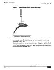
... DC power clip in -lb. See Figure 2-42. Power cord connector types vary by country. Power-cord color codes also vary by country. Note Use copper conductors only, rated at a minimum temperature of 167°F (75°C). Chapter 2 Switch Installation Connecting the Switch to the Power Converter Follow these two connectors. See Figure 2-41. OL-13017-01 Cisco IE 3000 Switch...
... DC power clip in -lb. See Figure 2-42. Power cord connector types vary by country. Power-cord color codes also vary by country. Note Use copper conductors only, rated at a minimum temperature of 167°F (75°C). Chapter 2 Switch Installation Connecting the Switch to the Power Converter Follow these two connectors. See Figure 2-41. OL-13017-01 Cisco IE 3000 Switch...

Installation Guide
Page 75
... AC/DC Power Input Terminal Block 202299 1 1 Ground wire Step 2 Insert the exposed ground wire lead into the AC outlet until you have completed wiring the line, neutral, and ground connections. Chapter 2 Switch Installation Connecting the Switch to the Power Converter Caution Do not insert the cord into the power converter ground wire connection. OL-13017-01 Cisco IE 3000 Switch...
... AC/DC Power Input Terminal Block 202299 1 1 Ground wire Step 2 Insert the exposed ground wire lead into the AC outlet until you have completed wiring the line, neutral, and ground connections. Chapter 2 Switch Installation Connecting the Switch to the Power Converter Caution Do not insert the cord into the power converter ground wire connection. OL-13017-01 Cisco IE 3000 Switch...
Installation Guide
Page 77
...Cisco IE 3000 Switch Hardware Installation Guide 2-51 Connect one end of 167°F (75°C). See Figure 2-45. Follow these steps to connect the power converter to earth ground, use 18-AWG twisted-pair copper wire, such as Belden part number 9344 or the equivalent. The wire color might differ depending on the power converter terminal... block. Chapter 2 Switch Installation Connecting the Switch to the Power Converter Connecting the Power Converter to a DC Power Source You can leave exposed wire from the power converter to the DC source, use...
...Cisco IE 3000 Switch Hardware Installation Guide 2-51 Connect one end of 167°F (75°C). See Figure 2-45. Follow these steps to connect the power converter to earth ground, use 18-AWG twisted-pair copper wire, such as Belden part number 9344 or the equivalent. The wire color might differ depending on the power converter terminal... block. Chapter 2 Switch Installation Connecting the Switch to the Power Converter Connecting the Power Converter to a DC Power Source You can leave exposed wire from the power converter to the DC source, use...

Installation Guide
Page 78
... of the DC-input power source wire extends from a DC-input power source can conduct harmful levels of the DC power source, and connect the black wire to at least 600 VAC/DC (such as the KLKD Midget fuse). 2-52 Cisco IE 3000 Switch Hardware Installation Guide...into the terminal block line and neutral connections. Connecting the Switch to the Power Converter Chapter 2 Switch Installation Figure 2-45 AC/DC Power Input Terminal Block Wire Connections to a DC Source 1 2 3 202301 1 Earth ground wire connection 2 Return wire connection (to DC return) 3 Positive DC connection Warning...
... of the DC-input power source wire extends from a DC-input power source can conduct harmful levels of the DC power source, and connect the black wire to at least 600 VAC/DC (such as the KLKD Midget fuse). 2-52 Cisco IE 3000 Switch Hardware Installation Guide...into the terminal block line and neutral connections. Connecting the Switch to the Power Converter Chapter 2 Switch Installation Figure 2-45 AC/DC Power Input Terminal Block Wire Connections to a DC Source 1 2 3 202301 1 Earth ground wire connection 2 Return wire connection (to DC return) 3 Positive DC connection Warning...
Installation Guide
Page 97
... connect the switch functional ground, you need a ring terminal lug (such as radios, power lines, and fluorescent lighting fixtures. • Connect the unit only to a Class 2 DC power source. If you want to connect a terminal to the switch console port...Cisco IE 3000 Switch Getting Started Guide (in . (65 mm) • Temperature surrounding the unit does not exceed 140°F (60°C). Front-panel direct current (DC) power and relay connector is within the enclosure is missing or damaged, contact your Cisco representative or reseller for damage. Top and bottom: 4.13 in an industrial...
... connect the switch functional ground, you need a ring terminal lug (such as radios, power lines, and fluorescent lighting fixtures. • Connect the unit only to a Class 2 DC power source. If you want to connect a terminal to the switch console port...Cisco IE 3000 Switch Getting Started Guide (in . (65 mm) • Temperature surrounding the unit does not exceed 140°F (60°C). Front-panel direct current (DC) power and relay connector is within the enclosure is missing or damaged, contact your Cisco representative or reseller for damage. Top and bottom: 4.13 in an industrial...

Installation Guide
Page 106
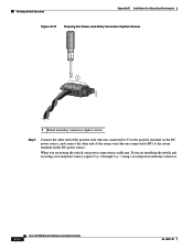
... to the switch, see the "Connecting the Switch to the terminal, if needed. Verifying Switch Operation Appendix B Installation In a Hazardous Environment Figure B-8 Connecting to the Console Port 201868 Step 4 Step 5 Step 6 Attach the appropriate adapter to the Power Converter" section on page B-49. Locate the power and relay connector in the switch accessory kit. B-16 Cisco IE 3000 Switch Hardware Installation...
... to the switch, see the "Connecting the Switch to the terminal, if needed. Verifying Switch Operation Appendix B Installation In a Hazardous Environment Figure B-8 Connecting to the Console Port 201868 Step 4 Step 5 Step 6 Attach the appropriate adapter to the Power Converter" section on page B-49. Locate the power and relay connector in the switch accessory kit. B-16 Cisco IE 3000 Switch Hardware Installation...
Installation Guide
Page 107
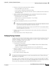
... Wire-stripping tools for number 10-to-12 AWG wire, such as Belden part number 9912 or equivalent) • For DC power connections, use a UL-listed ring terminal lug suitable for stripping 10- Statement 1064 Note Use at your site. Step 1 Use a standard Phillips screwdriver or a ... Ring terminal lug (such as Thomas & Bett part number 10RCR or equivalent) • Crimping tool (such as Thomas & Bett part number WT2000, ERG-2001, or equivalent) • 10-gauge copper ground wire (such as Thomas & Bett part number 10RCR or equivalent. OL-13017-01 Cisco IE 3000 Switch Hardware ...
... Wire-stripping tools for number 10-to-12 AWG wire, such as Belden part number 9912 or equivalent) • For DC power connections, use a UL-listed ring terminal lug suitable for stripping 10- Statement 1064 Note Use at your site. Step 1 Use a standard Phillips screwdriver or a ... Ring terminal lug (such as Thomas & Bett part number 10RCR or equivalent) • Crimping tool (such as Thomas & Bett part number WT2000, ERG-2001, or equivalent) • 10-gauge copper ground wire (such as Thomas & Bett part number 10RCR or equivalent. OL-13017-01 Cisco IE 3000 Switch Hardware ...
Installation Guide
Page 112
... Step 7 using a second power and relay connector. B-22 Cisco IE 3000 Switch Hardware Installation Guide OL-13017-01 When you are installing the switch and are testing the switch, one connected to RT) to the positive terminal on the DC power source, and connect the other end of the return wire (the one power connection is sufficient. Verifying Switch Operation Appendix B Installation...
... Step 7 using a second power and relay connector. B-22 Cisco IE 3000 Switch Hardware Installation Guide OL-13017-01 When you are installing the switch and are testing the switch, one connected to RT) to the positive terminal on the DC power source, and connect the other end of the return wire (the one power connection is sufficient. Verifying Switch Operation Appendix B Installation...
Installation Guide
Page 143
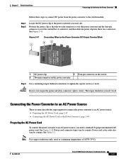
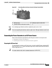
... captive screws. OL-13017-01 Cisco IE 3000 Switch Hardware Installation Guide B-53 See Table 2-2. Connecting the Power Converter to an AC Power Source These sections describe the steps required to connect the power converter to an AC power source: • Preparing the AC Power Cord, page B-53 • Connecting the AC Power Cord to the Power Converter, page B-54 Preparing...
... captive screws. OL-13017-01 Cisco IE 3000 Switch Hardware Installation Guide B-53 See Table 2-2. Connecting the Power Converter to an AC Power Source These sections describe the steps required to connect the power converter to an AC power source: • Preparing the AC Power Cord, page B-53 • Connecting the AC Power Cord to the Power Converter, page B-54 Preparing...
Installation Guide
Page 145
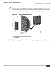
Appendix B Installation In a Hazardous Environment Connecting the Switch to the Power Converter Caution Do not insert the cord into the power converter ground wire connection. See Figure B-44. See Figure B-43. Figure B-43 AC/DC Power Input Terminal Block 202299 1 1 Ground wire Step 2 Insert the exposed ground wire ...the line, neutral, and ground connections. Make sure that only wire with insulation extends from the input power terminals and set it aside. Step 1 Remove the plastic cover from the connector. OL-13017-01 Cisco IE 3000 Switch Hardware Installation Guide B-55
Appendix B Installation In a Hazardous Environment Connecting the Switch to the Power Converter Caution Do not insert the cord into the power converter ground wire connection. See Figure B-44. See Figure B-43. Figure B-43 AC/DC Power Input Terminal Block 202299 1 1 Ground wire Step 2 Insert the exposed ground wire ...the line, neutral, and ground connections. Make sure that only wire with insulation extends from the input power terminals and set it aside. Step 1 Remove the plastic cover from the connector. OL-13017-01 Cisco IE 3000 Switch Hardware Installation Guide B-55
Installation Guide
Page 147
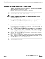
... In a Hazardous Environment Connecting the Switch to the Power Converter Connecting the Power Converter to a DC Power Source You can leave exposed wire from the power and relay connector after installation. The wire color might differ depending on the power converter terminal block. Using a 18-gauge wire...176;F (30°C) above surrounding ambient temperature outside the enclosure. OL-13017-01 Cisco IE 3000 Switch Hardware Installation Guide B-57 Follow these steps to connect the power converter to a DC power source. Insert the other end of 167°F (75°C).
... In a Hazardous Environment Connecting the Switch to the Power Converter Connecting the Power Converter to a DC Power Source You can leave exposed wire from the power and relay connector after installation. The wire color might differ depending on the power converter terminal block. Using a 18-gauge wire...176;F (30°C) above surrounding ambient temperature outside the enclosure. OL-13017-01 Cisco IE 3000 Switch Hardware Installation Guide B-57 Follow these steps to connect the power converter to a DC power source. Insert the other end of 167°F (75°C).

Installation Guide
Page 148
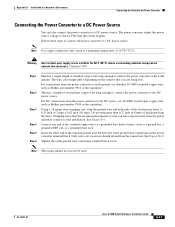
... red wire to the positive pole of the DC-input power source wire extends from the power and relay connector. Connecting the Switch to the Power Converter Appendix B Installation In a Hazardous Environment Figure B-45 AC/DC Power Input Terminal Block Wire Connections to a DC Source 1 2 3 202301 1 Earth ground ...labeled number 2 in -lb. Tighten the line and neutral terminal block screws. Note The torque should not exceed 10 in Figure B-45) lead into the terminal block line and neutral connections. B-58 Cisco IE 3000 Switch Hardware Installation Guide OL-13017-01 See Figure B-45.
... red wire to the positive pole of the DC-input power source wire extends from the power and relay connector. Connecting the Switch to the Power Converter Appendix B Installation In a Hazardous Environment Figure B-45 AC/DC Power Input Terminal Block Wire Connections to a DC Source 1 2 3 202301 1 Earth ground ...labeled number 2 in -lb. Tighten the line and neutral terminal block screws. Note The torque should not exceed 10 in Figure B-45) lead into the terminal block line and neutral connections. B-58 Cisco IE 3000 Switch Hardware Installation Guide OL-13017-01 See Figure B-45.
Installation Guide
Page 165
...C-5 connecting to 2-43, B-48 described 1-5 A AC/DC power converter, connecting to 2-44 to 2-53, B-49 to B-59 adapter pinouts, terminal RJ-45-to-DB-25 C-9 RJ-45-to-DB-9 C-8 adding modules to the switch B-8 airflow, required clearance 2-4, B-7 alarm relay connections connection... and cables Cisco IOS command-line interface 1-14 Cisco IP Phones, connecting to 2-36, B-41 Cisco Network Assistant 1-14 CiscoView 1-15 clearance 2-4, B-7 CLI 1-14 command-line interface See CLI compact flash memory card installing, removing 2-10, B-13 overview 1-11 Cisco IE 3000 Switch Hardware Installation Guide...
...C-5 connecting to 2-43, B-48 described 1-5 A AC/DC power converter, connecting to 2-44 to 2-53, B-49 to B-59 adapter pinouts, terminal RJ-45-to-DB-25 C-9 RJ-45-to-DB-9 C-8 adding modules to the switch B-8 airflow, required clearance 2-4, B-7 alarm relay connections connection... and cables Cisco IOS command-line interface 1-14 Cisco IP Phones, connecting to 2-36, B-41 Cisco Network Assistant 1-14 CiscoView 1-15 clearance 2-4, B-7 CLI 1-14 command-line interface See CLI compact flash memory card installing, removing 2-10, B-13 overview 1-11 Cisco IE 3000 Switch Hardware Installation Guide...
Installation Guide
Page 166
... B-11 to PC 2-12 to 2-13, B-15 to B-16 to power converter 2-44 to 2-53, B-49 to B-59 to SFP modules 2-41 to 2-42, B-45 to B-46 to terminal 2-12 to 2-13, B-15 to B-16 connectors and cables 10/100/... A-3 dual-purpose ports connectors and cables C-4 described 1-5 LEDs 1-11 IN-2 Cisco IE 3000 Switch Hardware Installation Guide duplex, troubleshooting 3-4 E electrical noise, avoiding 2-4, B-7 environmental ranges A-3 environmental temperatures A-2 ESD, requirements 2-3, B-6 Ethernet and fiber cable troubleshooting 3-2 exposed DC power wire warning 2-17, 2-52, B-21, B-58 F fiber-optic cables C-3...
... B-11 to PC 2-12 to 2-13, B-15 to B-16 to power converter 2-44 to 2-53, B-49 to B-59 to SFP modules 2-41 to 2-42, B-45 to B-46 to terminal 2-12 to 2-13, B-15 to B-16 connectors and cables 10/100/... A-3 dual-purpose ports connectors and cables C-4 described 1-5 LEDs 1-11 IN-2 Cisco IE 3000 Switch Hardware Installation Guide duplex, troubleshooting 3-4 E electrical noise, avoiding 2-4, B-7 environmental ranges A-3 environmental temperatures A-2 ESD, requirements 2-3, B-6 Ethernet and fiber cable troubleshooting 3-2 exposed DC power wire warning 2-17, 2-52, B-21, B-58 F fiber-optic cables C-3...
Installation Guide
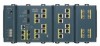
Page 167
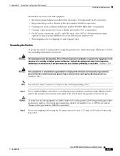
...DC power B-3 disconnecting the console cable B-3 disconnecting the power and relay connector B-3 disconnecting the wiring B-4 nonhazardous area for installation B-4 power and relay connector B-3, B-24 substitution of components B-4 HP OpenView 1-15 humidity A-2 I IE-3000-4TC switch, illustrated 1-3 IE-3000-8TC switch, illustrated 1-3 IEM-3000-8FM module, illustrated 1-4 IEM-3000-8TM module, illustrated 1-4 industrial...clearance 2-4, B-7 SFP modules 2-38 to 2-40, B-43 to B-44 starting the terminal emulation software D-1 verifying switch operation 2-11 to 2-22, B-14 to B-25 wall 2-27, B-27 wiring ...
...DC power B-3 disconnecting the console cable B-3 disconnecting the power and relay connector B-3 disconnecting the wiring B-4 nonhazardous area for installation B-4 power and relay connector B-3, B-24 substitution of components B-4 HP OpenView 1-15 humidity A-2 I IE-3000-4TC switch, illustrated 1-3 IE-3000-8TC switch, illustrated 1-3 IEM-3000-8FM module, illustrated 1-4 IEM-3000-8TM module, illustrated 1-4 industrial...clearance 2-4, B-7 SFP modules 2-38 to 2-40, B-43 to B-44 starting the terminal emulation software D-1 verifying switch operation 2-11 to 2-22, B-14 to B-25 wall 2-27, B-27 wiring ...
