
Installation Guide
Page 16
...can order a kit (part number ACS-DSBUASYN=) with both power sources are operational, the switch draws power from Cisco Systems. For console-port and adapter-pinout information, see Appendix C, "Cable and Connectors." Cisco IE 3000 Switch Hardware Installation Guide 1-6 OL-13017-01 These connectors provide screw terminals for environmental, power supply, and port...and relay receptacles on configuring the alarm relays. Figure 1-6 to complete an electrical circuit. Console Port You can get replacement power and relay connectors (PWR-IE3000-CNCT=) by calling Cisco Technical Support.
...can order a kit (part number ACS-DSBUASYN=) with both power sources are operational, the switch draws power from Cisco Systems. For console-port and adapter-pinout information, see Appendix C, "Cable and Connectors." Cisco IE 3000 Switch Hardware Installation Guide 1-6 OL-13017-01 These connectors provide screw terminals for environmental, power supply, and port...and relay receptacles on configuring the alarm relays. Figure 1-6 to complete an electrical circuit. Console Port You can get replacement power and relay connectors (PWR-IE3000-CNCT=) by calling Cisco Technical Support.
Installation Guide
Page 17
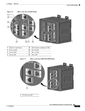
Chapter 1 Overview Figure 1-6 1 2 3 4 LEDs on the Cisco IE 3000 Switch Front-Panel Description 201703 5 67 8 1 Express setup button 2 System LED 3 Alarm LED 4 Setup LED 5 Dual-purpose uplink port LED 6 Pwr B LED 7 Pwr A LED 8 Port LED Figure 1-7 LEDs on the Cisco IEM-3000-8TM Module 201706 1 1 10/100 port LED OL-13017-01 Cisco IE 3000 Switch Hardware Installation Guide 1-7
Chapter 1 Overview Figure 1-6 1 2 3 4 LEDs on the Cisco IE 3000 Switch Front-Panel Description 201703 5 67 8 1 Express setup button 2 System LED 3 Alarm LED 4 Setup LED 5 Dual-purpose uplink port LED 6 Pwr B LED 7 Pwr A LED 8 Port LED Figure 1-7 LEDs on the Cisco IEM-3000-8TM Module 201706 1 1 10/100 port LED OL-13017-01 Cisco IE 3000 Switch Hardware Installation Guide 1-7

Installation Guide
Page 20
..., and errors such as shown in Figure 1-6, Figure 1-7, and Figure 1-8. For information about the switch and the individual ports. Note After a port is disabled. 1-10 Cisco IE 3000 Switch Hardware Installation Guide OL-13017-01 See Table 1-7. Port is present if the voltage at values near 18 V. The power status LEDs only show... is not forwarding. Port is sending or receiving data. A link blocked by management, an address violation, or STP. Front-Panel Description Chapter 1 Overview Note The Pwr A and Pwr B LEDs show that power is sending or receiving data.
..., and errors such as shown in Figure 1-6, Figure 1-7, and Figure 1-8. For information about the switch and the individual ports. Note After a port is disabled. 1-10 Cisco IE 3000 Switch Hardware Installation Guide OL-13017-01 See Table 1-7. Port is present if the voltage at values near 18 V. The power status LEDs only show... is not forwarding. Port is sending or receiving data. A link blocked by management, an address violation, or STP. Front-Panel Description Chapter 1 Overview Note The Pwr A and Pwr B LEDs show that power is sending or receiving data.
Installation Guide
Page 23
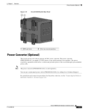
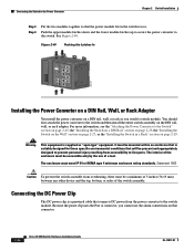
... up to the switch through a preassembled power cable. The power converter is sold separately. The power converter (PWR-IE3000-AC) can be used with an optional AC/DC power converter. OL-13017-01 Cisco IE 3000 Switch Hardware Installation Guide 1-13 For installation and connection procedures for the power converter, see the "Connecting the...
... up to the switch through a preassembled power cable. The power converter is sold separately. The power converter (PWR-IE3000-AC) can be used with an optional AC/DC power converter. OL-13017-01 Cisco IE 3000 Switch Hardware Installation Guide 1-13 For installation and connection procedures for the power converter, see the "Connecting the...
Installation Guide
Page 39
...optional AC/DC power converter (PWR-IE3000-AC). Contact the appropriate electrical inspection authority or an electrician if you are uncertain that exerts up to 15 inch-pounds (in the absence of the adapter cable to the Switch, page 2-21 Note The Cisco IE 3000 switch can get replacement power and... relay connectors (PWR-IE3000-CNCT=) by using the ground screw, follow any grounding requirements at your site. Locate the power and relay ...
...optional AC/DC power converter (PWR-IE3000-AC). Contact the appropriate electrical inspection authority or an electrician if you are uncertain that exerts up to 15 inch-pounds (in the absence of the adapter cable to the Switch, page 2-21 Note The Cisco IE 3000 switch can get replacement power and... relay connectors (PWR-IE3000-CNCT=) by using the ground screw, follow any grounding requirements at your site. Locate the power and relay ...

Installation Guide
Page 47
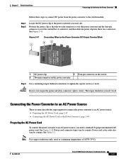
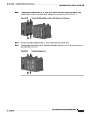
...Figure 2-17 1 Connecting the Power and Relay Connector to the Switch 2 V RT A A V RT A A 201858 43 1 Power source A connector 2 Pwr A receptacle 3 Pwr B receptacle 4 Power source B connector Step 2 Use a racheting torque flathead screwdriver to the rack. For example, use tie wraps to secure the wires to tighten...secure the wires coming from the power and relay connector so that they cannot be disturbed by casual contact. OL-13017-01 Cisco IE 3000 Switch Hardware Installation Guide 2-21 When you are installing the switch and are testing the switch, one power source is sufficient....
...Figure 2-17 1 Connecting the Power and Relay Connector to the Switch 2 V RT A A V RT A A 201858 43 1 Power source A connector 2 Pwr A receptacle 3 Pwr B receptacle 4 Power source B connector Step 2 Use a racheting torque flathead screwdriver to the rack. For example, use tie wraps to secure the wires to tighten...secure the wires coming from the power and relay connector so that they cannot be disturbed by casual contact. OL-13017-01 Cisco IE 3000 Switch Hardware Installation Guide 2-21 When you are installing the switch and are testing the switch, one power source is sufficient....
Installation Guide
Page 48
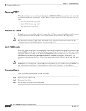
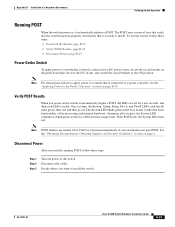
...Documentation, Obtaining Support, and Security Guidelines" section on the panel board that it automatically initiates a POST. Call Cisco Systems immediately if your switch does not pass POST. Disconnect Power After successfully running POST, follow these steps. ...at a time, the System, Alarm, Setup, Pwr A, and Pwr B LEDs each LED is directly connected to a switch that is tested. The System LED blinks green as the Cisco IOS software image loads. If the POST fails,... breaker to install the switch. 2-22 Cisco IE 3000 Switch Hardware Installation Guide OL-13017-01
...Documentation, Obtaining Support, and Security Guidelines" section on the panel board that it automatically initiates a POST. Call Cisco Systems immediately if your switch does not pass POST. Disconnect Power After successfully running POST, follow these steps. ...at a time, the System, Alarm, Setup, Pwr A, and Pwr B LEDs each LED is directly connected to a switch that is tested. The System LED blinks green as the Cisco IOS software image loads. If the POST fails,... breaker to install the switch. 2-22 Cisco IE 3000 Switch Hardware Installation Guide OL-13017-01

Installation Guide
Page 70
...have an established link. The LED turns amber while the STP discovers the network topology and searches for solutions to the Power Converter The Cisco IE 3000 switch can be used with the adapter installed in the target device. If an LED is off, the target device might not be ... with an optional AC/DC power converter (PWR-IE3000-AC). This process takes about 30 seconds, and then the port LED turns green. Connecting the Switch to the Power Converter Figure 2-37 Connecting to the Power Converter, page 2-53 2-44 Cisco IE 3000 Switch Hardware Installation Guide OL-13017-01 These...
...have an established link. The LED turns amber while the STP discovers the network topology and searches for solutions to the Power Converter The Cisco IE 3000 switch can be used with the adapter installed in the target device. If an LED is off, the target device might not be ... with an optional AC/DC power converter (PWR-IE3000-AC). This process takes about 30 seconds, and then the port LED turns green. Connecting the Switch to the Power Converter Figure 2-37 Connecting to the Power Converter, page 2-53 2-44 Cisco IE 3000 Switch Hardware Installation Guide OL-13017-01 These...
Installation Guide
Page 72
...then install the entire switch assembly on page 2-27, or the "Installing the Switch in the switch recess. Because the power clip uses the Pwr A connector, you would a switch module. Statement 1063 Caution To prevent the switch assemble from accessibility to live parts. Connecting the DC Power...from the power converter to the switch module. The enclosure must be accessible only by the use the alarm connections on that connector. 2-46 Cisco IE 3000 Switch Hardware Installation Guide OL-13017-01 It must be a minimum of 3 inches (76.19 mm) between any other device and the top...
...then install the entire switch assembly on page 2-27, or the "Installing the Switch in the switch recess. Because the power clip uses the Pwr A connector, you would a switch module. Statement 1063 Caution To prevent the switch assemble from accessibility to live parts. Connecting the DC Power...from the power converter to the switch module. The enclosure must be accessible only by the use the alarm connections on that connector. 2-46 Cisco IE 3000 Switch Hardware Installation Guide OL-13017-01 It must be a minimum of 3 inches (76.19 mm) between any other device and the top...
Installation Guide
Page 73
... minimum temperature of 167°F (75°C). See Table 2-2. See Figure 2-41. Power cord connector types vary by country. OL-13017-01 Cisco IE 3000 Switch Hardware Installation Guide 2-47 Connecting the Power Converter to an AC Power Source These sections describe the steps required to connect the power converter... Converter, page 2-48 Preparing the AC Power Cord To connect the power converter to 2 in-lb. Caution Do not over the switch Pwr A connector, and then slide the power clip into these steps to connect DC power from the power converter to the switch module. Power...
... minimum temperature of 167°F (75°C). See Table 2-2. See Figure 2-41. Power cord connector types vary by country. OL-13017-01 Cisco IE 3000 Switch Hardware Installation Guide 2-47 Connecting the Power Converter to an AC Power Source These sections describe the steps required to connect the power converter... Converter, page 2-48 Preparing the AC Power Cord To connect the power converter to 2 in-lb. Caution Do not over the switch Pwr A connector, and then slide the power clip into these steps to connect DC power from the power converter to the switch module. Power...
Installation Guide
Page 81
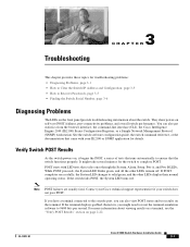
... support representative if your IE2100 or SNMP application for details. OL-13017-01 Cisco IE 3000 Switch Hardware Installation Guide 3-1 See the switch software configuration guide, the switch command reference, or the documentation that came with LED tests that the switch ... As the switch powers on, it begins the POST, a series of tests that runs automatically to ensure that cycles once through the System, Alarm, Setup, Pwr A, and Pwr B LEDs. If the terminal displays garbled characters, you can also get statistics from the browser interface, the command-line interface (CLI), the...
... support representative if your IE2100 or SNMP application for details. OL-13017-01 Cisco IE 3000 Switch Hardware Installation Guide 3-1 See the switch software configuration guide, the switch command reference, or the documentation that came with LED tests that the switch ... As the switch powers on, it begins the POST, a series of tests that runs automatically to ensure that cycles once through the System, Alarm, Setup, Pwr A, and Pwr B LEDs. If the terminal displays garbled characters, you can also get statistics from the browser interface, the command-line interface (CLI), the...

Installation Guide
Page 106
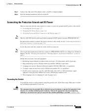
...the power and relay connector in the switch accessory kit. Note You can be used with an optional AC/DC power converter (PWR-IE3000-AC). Connecting the Protective Ground and DC Power These sections describe the steps required to connect a protective ground and DC ... Step 6 Attach the appropriate adapter to the Power Converter" section on page B-49. Start the terminal-emulation software on page x. B-16 Cisco IE 3000 Switch Hardware Installation Guide OL-13017-01 See the "Obtaining Documentation, Obtaining Support, and Security Guidelines" section on the PC. Connect the other ...
...the power and relay connector in the switch accessory kit. Note You can be used with an optional AC/DC power converter (PWR-IE3000-AC). Connecting the Protective Ground and DC Power These sections describe the steps required to connect a protective ground and DC ... Step 6 Attach the appropriate adapter to the Power Converter" section on page B-49. Start the terminal-emulation software on page x. B-16 Cisco IE 3000 Switch Hardware Installation Guide OL-13017-01 See the "Obtaining Documentation, Obtaining Support, and Security Guidelines" section on the PC. Connect the other ...

Installation Guide
Page 114
...electrical arc can result in hazardous area installations. Failure to securely tighten the power and relay connector captive screws can occur. B-24 Cisco IE 3000 Switch Hardware Installation Guide OL-13017-01 Statement 1058 Figure B-17 1 Connecting the Power and Relay Connector to the Switch 2 ...V RT A A V RT A A 201858 43 1 Power source A connector 2 Pwr A receptacle 3 Pwr B receptacle 4 Power source B connector Step 2 Use a ratcheting torque flathead screwdriver to the rack. Warning When you are using a second ...
...electrical arc can result in hazardous area installations. Failure to securely tighten the power and relay connector captive screws can occur. B-24 Cisco IE 3000 Switch Hardware Installation Guide OL-13017-01 Statement 1058 Figure B-17 1 Connecting the Power and Relay Connector to the Switch 2 ...V RT A A V RT A A 201858 43 1 Power source A connector 2 Pwr A receptacle 3 Pwr B receptacle 4 Power source B connector Step 2 Use a ratcheting torque flathead screwdriver to the rack. Warning When you are using a second ...
Installation Guide
Page 115
... pass, the System LED continues to the switch. Decide where you power on the switch, it automatically initiates a POST. OL-13017-01 Cisco IE 3000 Switch Hardware Installation Guide B-25 To test the switch, follow these steps: • Power On the Switch, page B-25 • Verify... runs a series of the processing and memory hardware. All LEDs are usually fatal. One at a time, the System, Alarm, Setup, Pwr A, and Pwr B LEDs each LED is ready to install the switch. Disconnect the cables. See the "Obtaining Documentation, Obtaining Support, and Security Guidelines" ...
... pass, the System LED continues to the switch. Decide where you power on the switch, it automatically initiates a POST. OL-13017-01 Cisco IE 3000 Switch Hardware Installation Guide B-25 To test the switch, follow these steps: • Power On the Switch, page B-25 • Verify... runs a series of the processing and memory hardware. All LEDs are usually fatal. One at a time, the System, Alarm, Setup, Pwr A, and Pwr B LEDs each LED is ready to install the switch. Disconnect the cables. See the "Obtaining Documentation, Obtaining Support, and Security Guidelines" ...

Installation Guide
Page 139
... is nonhazardous before proceeding. Connecting the Switch to the Power Converter The Cisco IE 3000 switch can occur. Statement 1081 OL-13017-01 Cisco IE 3000 Switch Hardware Installation Guide B-49 an electrical arc can be a problem with an optional AC/DC power converter (PWR-IE3000-AC). See Chapter 3, "Troubleshooting," for solutions to the switch: Warning Explosion...
... is nonhazardous before proceeding. Connecting the Switch to the Power Converter The Cisco IE 3000 switch can occur. Statement 1081 OL-13017-01 Cisco IE 3000 Switch Hardware Installation Guide B-49 an electrical arc can be a problem with an optional AC/DC power converter (PWR-IE3000-AC). See Chapter 3, "Troubleshooting," for solutions to the switch: Warning Explosion...
Installation Guide
Page 141
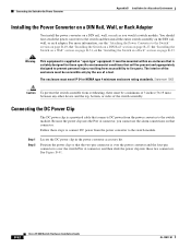
... or 48 VDC) 1 Rtn B 6 Minor Alarm 2 Express Setup System Pwr A Alarm Pwr B 7 Setup 1 3 8 2 4 Cisco Catalyst OL-13017-01 Cisco IE 3000 Switch Hardware Installation Guide B-51 Push the upper module latches down . See Figure B-39. Appendix B Installation In a Hazardous Environment Connecting the Switch to the Power ... Step 3 Step 4 Put the two modules together so that the power module fits in the switch recess. Figure B-40 Pushing the Latches In CONSOLE 202297 Pwr A (24VDC or 48 VDC) Rtn A Major Alarm 5 !
... or 48 VDC) 1 Rtn B 6 Minor Alarm 2 Express Setup System Pwr A Alarm Pwr B 7 Setup 1 3 8 2 4 Cisco Catalyst OL-13017-01 Cisco IE 3000 Switch Hardware Installation Guide B-51 Push the upper module latches down . See Figure B-39. Appendix B Installation In a Hazardous Environment Connecting the Switch to the Power ... Step 3 Step 4 Put the two modules together so that the power module fits in the switch recess. Figure B-40 Pushing the Latches In CONSOLE 202297 Pwr A (24VDC or 48 VDC) Rtn A Major Alarm 5 !
Installation Guide
Page 142
It must meet IP 54 or NEMA type 4 minimum enclosure rating standards. B-52 Cisco IE 3000 Switch Hardware Installation Guide OL-13017-01 For more information, see the "Attaching the Power Converter to the Switch" section on page B-49, the "Installing ... cable that connects DC power from the power converter to the switch module. Because the power clip uses the Pwr A connector, you would a switch module. Warning This equipment is over the switch Pwr A connector, and then slide the power clip into these steps to connect DC power from the power converter to...
It must meet IP 54 or NEMA type 4 minimum enclosure rating standards. B-52 Cisco IE 3000 Switch Hardware Installation Guide OL-13017-01 For more information, see the "Attaching the Power Converter to the Switch" section on page B-49, the "Installing ... cable that connects DC power from the power converter to the switch module. Because the power clip uses the Pwr A connector, you would a switch module. Warning This equipment is over the switch Pwr A connector, and then slide the power clip into these steps to connect DC power from the power converter to...

Getting Started Guide
Page 2
... documents that accompanies this publication, see the hardware installation guide on Cisco.com. Note For information about using the switch with the optional PWR-IE3000-AC power converter module, see the Regulatory Compliance and Safety Information for the Cisco IE 3000 Switch that match the Cisco IOS software version running on the switch. When you have...
... documents that accompanies this publication, see the hardware installation guide on Cisco.com. Note For information about using the switch with the optional PWR-IE3000-AC power converter module, see the Regulatory Compliance and Safety Information for the Cisco IE 3000 Switch that match the Cisco IOS software version running on the switch. When you have...

Getting Started Guide
Page 6
..."In Case of tests verify that the System LED is solid green. Press the Express Setup button. Express Setup System Alarm Setup Pwr A Pwr B 2 201877 Cisco IE 3000 Switch Getting Started Guide 6 OL-16234-01 During POST, the System LED blinks while a series of Difficulty" section on self-test... This button is recessed behind the front panel, so you press the Express Setup button, a switch port LED begins blinking green. Cisco IE 3000 Switch Getting Started Guide To run Express Setup: Step 1 Make sure that nothing is connected to complete POST, which takes approximately 1 ...
..."In Case of tests verify that the System LED is solid green. Press the Express Setup button. Express Setup System Alarm Setup Pwr A Pwr B 2 201877 Cisco IE 3000 Switch Getting Started Guide 6 OL-16234-01 During POST, the System LED blinks while a series of Difficulty" section on self-test... This button is recessed behind the front panel, so you press the Express Setup button, a switch port LED begins blinking green. Cisco IE 3000 Switch Getting Started Guide To run Express Setup: Step 1 Make sure that nothing is connected to complete POST, which takes approximately 1 ...

Getting Started Guide
Page 20
...second power source, repeat Step 3 through Step 7 using a second power and relay connector. Step 1 Insert the power and relay connector into the Pwr A receptacle on the switch front panel. When you are installing the switch and are testing the switch, one connected to RT) to the return terminal... of the alarm circuits must be an isolated source and limited to less than or equal to 30 VDC, 1 A. Cisco IE 3000 Switch Getting Started Guide 20 OL-16234-01 Cisco IE 3000 Switch Getting Started Guide Step 7 Step 8 Connect the other end of the positive wire (the one connected to V) ...
...second power source, repeat Step 3 through Step 7 using a second power and relay connector. Step 1 Insert the power and relay connector into the Pwr A receptacle on the switch front panel. When you are installing the switch and are testing the switch, one connected to RT) to the return terminal... of the alarm circuits must be an isolated source and limited to less than or equal to 30 VDC, 1 A. Cisco IE 3000 Switch Getting Started Guide 20 OL-16234-01 Cisco IE 3000 Switch Getting Started Guide Step 7 Step 8 Connect the other end of the positive wire (the one connected to V) ...