
Hardware Installation Guide
Page 9
... Cabling Configurations 3-15 Installing the Switch 3-17 Rack Mounting 3-18 Removing Screws from the Switch 3-19 Attaching Brackets to the Catalyst 3750G-24TS Switch 3-20 Attaching Brackets to the Catalyst 3750-24TS, 3750G-24T, 3750G-12S, and 3750-48TS Switches 3-25 Mounting the Switch in a Rack 3-28 Attaching the Cable Guide 3-30 Wall Mounting 3-32... 3-32 Attaching the RPS Connector Cover 3-33 Mounting the Switch on a Wall 3-34 Table or Shelf Mounting 3-36 Connecting StackWise Cable to StackWise Ports 3-37 Catalyst 3750 Switch Hardware Installation Guide vii
... Cabling Configurations 3-15 Installing the Switch 3-17 Rack Mounting 3-18 Removing Screws from the Switch 3-19 Attaching Brackets to the Catalyst 3750G-24TS Switch 3-20 Attaching Brackets to the Catalyst 3750-24TS, 3750G-24T, 3750G-12S, and 3750-48TS Switches 3-25 Mounting the Switch in a Rack 3-28 Attaching the Cable Guide 3-30 Wall Mounting 3-32... 3-32 Attaching the RPS Connector Cover 3-33 Mounting the Switch on a Wall 3-34 Table or Shelf Mounting 3-36 Connecting StackWise Cable to StackWise Ports 3-37 Catalyst 3750 Switch Hardware Installation Guide vii
Hardware Installation Guide
Page 42
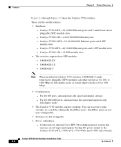
...- 1000BASE-SX - 1000BASE-LX - 1000BASE-T Note When installed in Catalyst 3750 switches, 1000BASE-T small form-factor pluggable (SFP) modules can stack up to the Catalyst 3750-24TS, 3750G-24T, 3750-48TS, and 3750G-12S switches. Catalyst 3750G-24T-24 10/100/1000 Ethernet ports - These are hot-swappable... ports and 4 SFP module slots - Features Chapter 2 Product Overview Figure 2-1 through Figure 2-5 show the Catalyst 3750 switches. Connection for optional Cisco RPS 300 redundant power system that operates on AC input and supplies backup DC power output to nine switches in...
...- 1000BASE-SX - 1000BASE-LX - 1000BASE-T Note When installed in Catalyst 3750 switches, 1000BASE-T small form-factor pluggable (SFP) modules can stack up to the Catalyst 3750-24TS, 3750G-24T, 3750-48TS, and 3750G-12S switches. Catalyst 3750G-24T-24 10/100/1000 Ethernet ports - These are hot-swappable... ports and 4 SFP module slots - Features Chapter 2 Product Overview Figure 2-1 through Figure 2-5 show the Catalyst 3750 switches. Connection for optional Cisco RPS 300 redundant power system that operates on AC input and supplies backup DC power output to nine switches in...
Hardware Installation Guide
Page 43
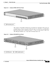
...as shown in pairs. Port 3 is above the second member (port 2) on the Catalyst 3750G-24T and 3750G-24TS are numbered 25 to the family of Catalyst 3750 switches. Connection for optional Cisco RPS 675 redundant power system that operates on . The first member of the pair ...3 is above the second member (port 2) on . The SFP port numbers are grouped in Figure 2-1. Front Panel Description The Catalyst 3750-24TS 10/100 ports are numbered 1 through 24. Chapter 2 Product Overview Front Panel Description Note The Cisco RPS 300 does not support the Catalyst 3750G-24TS switch. -
...as shown in pairs. Port 3 is above the second member (port 2) on the Catalyst 3750G-24T and 3750G-24TS are numbered 25 to the family of Catalyst 3750 switches. Connection for optional Cisco RPS 675 redundant power system that operates on . The first member of the pair ...3 is above the second member (port 2) on . The SFP port numbers are grouped in Figure 2-1. Front Panel Description The Catalyst 3750-24TS 10/100 ports are numbered 1 through 24. Chapter 2 Product Overview Front Panel Description Note The Cisco RPS 300 does not support the Catalyst 3750G-24TS switch. -
Hardware Installation Guide
Page 44
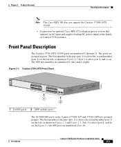
...78-15136-02 The ports are numbered 1 through 12. Front Panel Description Figure 2-2 Catalyst 3750G-24T Front Panel SYST RPS MASTR STAT DUPLX SPEED STACK MODE 12 1X 34 56 ... 13X 15 16 17 18 19 20 21 22 23 24 23X 14X 24X 1 Catalyst 3750 SERIES 1 10/100/1000 ports Figure 2-3 Catalyst 3750G-24TS Front Panel Chapter 2 Product Overview 86543 86544 SYST RPS MASTR STAT DUPLX SPEED ... 16 17 18 19 20 21 22 23 24 23X 14X 24X Catalyst 3750 SERIES 25 26 27 28 1 2 1 10/100 ports 2 SFP module ports The Catalyst 3750G-12S SFP module slots are grouped in three sets of four, as...
...78-15136-02 The ports are numbered 1 through 12. Front Panel Description Figure 2-2 Catalyst 3750G-24T Front Panel SYST RPS MASTR STAT DUPLX SPEED STACK MODE 12 1X 34 56 ... 13X 15 16 17 18 19 20 21 22 23 24 23X 14X 24X 1 Catalyst 3750 SERIES 1 10/100/1000 ports Figure 2-3 Catalyst 3750G-24TS Front Panel Chapter 2 Product Overview 86543 86544 SYST RPS MASTR STAT DUPLX SPEED ... 16 17 18 19 20 21 22 23 24 23X 14X 24X Catalyst 3750 SERIES 25 26 27 28 1 2 1 10/100 ports 2 SFP module ports The Catalyst 3750G-12S SFP module slots are grouped in three sets of four, as...
Hardware Installation Guide
Page 45
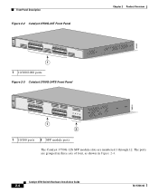
... 38 39 40 41 42 43 44 45 46 47 48 47X 32X 34X 48X Catalyst 3750 SERIES 1 3 2 4 1 2 1 10/100 ports 2 SFP module ports 78-15136-02 Catalyst 3750 Switch Hardware Installation Guide 2-5 Chapter 2 Product Overview Figure 2-4 Catalyst 3750G-12S Front Panel Front Panel Description 97166 SYST RPS MASTR STAT DUPLX SPEED STACK MODE...
... 38 39 40 41 42 43 44 45 46 47 48 47X 32X 34X 48X Catalyst 3750 SERIES 1 3 2 4 1 2 1 10/100 ports 2 SFP module ports 78-15136-02 Catalyst 3750 Switch Hardware Installation Guide 2-5 Chapter 2 Product Overview Figure 2-4 Catalyst 3750G-12S Front Panel Front Panel Description 97166 SYST RPS MASTR STAT DUPLX SPEED STACK MODE...
Hardware Installation Guide
Page 50
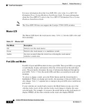
...same selected mode. An error occurred when the switch was selecting the stack master switch or a stack error. Note The Cisco RPS 300 does not support the Catalyst 3750G-24TS switches. Switch is the stack master or a standalone switch. Table 2-2 lists the LED colors and their associated ...port mode and meaning. These port LEDs, as a group or individually, display information about the switch and about the Cisco RPS 300, refer ...
...same selected mode. An error occurred when the switch was selecting the stack master switch or a stack error. Note The Cisco RPS 300 does not support the Catalyst 3750G-24TS switches. Switch is the stack master or a standalone switch. Table 2-2 lists the LED colors and their associated ...port mode and meaning. These port LEDs, as a group or individually, display information about the switch and about the Cisco RPS 300, refer ...
Hardware Installation Guide
Page 53
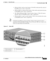
... switch show the status for StackWise ports 1 and 2, respectively. • The 10/100/1000 port LEDs 23 and 24 on the Catalyst 3750G-24T switch show the status for StackWise ports 1 and 2, respectively. Note If both the port LEDs are not green, the stack is operating ...2 10 3 48X 4 11 12 13 1 2 3 86686 1 Stack member 8 2 Stack member 3 3 Stack member 4 78-15136-02 Catalyst 3750 Switch Hardware Installation Guide 2-13 If any of the port LEDs are green on the Catalyst 3750G-12S switch show the status for StackWise ports 1 and 2, respectively. • SFP port LEDs 11 and 12 on...
... switch show the status for StackWise ports 1 and 2, respectively. • The 10/100/1000 port LEDs 23 and 24 on the Catalyst 3750G-24T switch show the status for StackWise ports 1 and 2, respectively. Note If both the port LEDs are not green, the stack is operating ...2 10 3 48X 4 11 12 13 1 2 3 86686 1 Stack member 8 2 Stack member 3 3 Stack member 4 78-15136-02 Catalyst 3750 Switch Hardware Installation Guide 2-13 If any of the port LEDs are green on the Catalyst 3750G-12S switch show the status for StackWise ports 1 and 2, respectively. • SFP port LEDs 11 and 12 on...
Hardware Installation Guide
Page 55
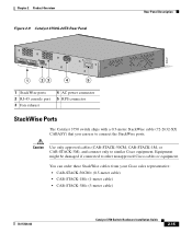
You can use to similar Cisco equipment. Caution Use only approved cables (CAB-STACK-50CM, CAB-STACK-1M, or CAB-STACK-3M), and connect only to connect the StackWise ports. Chapter 2 Product Overview Figure 2-9 Catalyst 3750G-24TS Rear Panel Rear Panel Description 86547 STACK 1 STACK 2 CONSOLE DSCPIENPCPO+IUWF1TI2EESvDRFISO@NUR1MP7RPAaELNYMUOATLE 1 23 4 5 1 StackWise ports 2 RJ-45...
You can use to similar Cisco equipment. Caution Use only approved cables (CAB-STACK-50CM, CAB-STACK-1M, or CAB-STACK-3M), and connect only to connect the StackWise ports. Chapter 2 Product Overview Figure 2-9 Catalyst 3750G-24TS Rear Panel Rear Panel Description 86547 STACK 1 STACK 2 CONSOLE DSCPIENPCPO+IUWF1TI2EESvDRFISO@NUR1MP7RPAaELNYMUOATLE 1 23 4 5 1 StackWise ports 2 RJ-45...
Hardware Installation Guide
Page 56
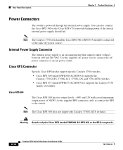
... Power Supply Connector The internal power supply is powered through the internal power supply. Note The Cisco RPS 300 does not support the Catalyst 3750G-24TS switches. You can also connect the Cisco RPS 300 or the Cisco RPS 675 to provide backup power if the switch internal power supply should be connected to an...
... Power Supply Connector The internal power supply is powered through the internal power supply. Note The Cisco RPS 300 does not support the Catalyst 3750G-24TS switches. You can also connect the Cisco RPS 300 or the Cisco RPS 675 to provide backup power if the switch internal power supply should be connected to an...
Hardware Installation Guide
Page 67
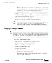
...;C). If you do not have access to the rear panel, make sure you cable the switches before you are planning to the switch (Catalyst 3750G-24TS switch) 78-15136-02 Catalyst 3750 Switch Hardware Installation Guide 3-7 Four Phillips flat-head screws for mounting the switch on a table - Note If the switch is shipped... is unrestricted. • Temperature around it . Verifying Package Contents Note Carefully remove the contents from other devices that there is missing or damaged, contact your Cisco representative or reseller for support.
...;C). If you do not have access to the rear panel, make sure you cable the switches before you are planning to the switch (Catalyst 3750G-24TS switch) 78-15136-02 Catalyst 3750 Switch Hardware Installation Guide 3-7 Four Phillips flat-head screws for mounting the switch on a table - Note If the switch is shipped... is unrestricted. • Temperature around it . Verifying Package Contents Note Carefully remove the contents from other devices that there is missing or damaged, contact your Cisco representative or reseller for support.
Hardware Installation Guide
Page 72
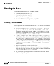
...Chapter 3 Switch Installation Planning the Stack If you plan to stack your Cisco supplier. Depending on the configurations you have access to the switch software configuration guide. 3-12 Catalyst 3750 Switch Hardware Installation Guide 78-15136-02 For cable numbers, see the...8226; Size of cable. The "Recommended Cabling Configurations" section on page 2-15. The Catalyst 3750-24TS, 3750G-24TS, and 3750-48TS switches are the same depth, and the Catalyst 3750G-12S and 3750G-24T switches are planning to stack the switches. Stacking switches of recommended configurations. •...
...Chapter 3 Switch Installation Planning the Stack If you plan to stack your Cisco supplier. Depending on the configurations you have access to the switch software configuration guide. 3-12 Catalyst 3750 Switch Hardware Installation Guide 78-15136-02 For cable numbers, see the...8226; Size of cable. The "Recommended Cabling Configurations" section on page 2-15. The Catalyst 3750-24TS, 3750G-24TS, and 3750-48TS switches are the same depth, and the Catalyst 3750G-12S and 3750G-24T switches are planning to stack the switches. Stacking switches of recommended configurations. •...
Hardware Installation Guide
Page 78
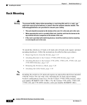
... instructions described in these procedures: • Removing Screws from Cisco. You can order a kit containing the 24-inch rack-mounting brackets and hardware from the Switch, page 3-19 • Attaching Brackets to the Catalyst 3750G-24TS Switch, page 3-20 • Attaching Brackets to ensure... that the system remains stable. For the Catalyst 3750G-24TS switches, order part number RCKMNT-3550-1.5RU=. Installing the Switch Rack Mounting ...
... instructions described in these procedures: • Removing Screws from Cisco. You can order a kit containing the 24-inch rack-mounting brackets and hardware from the Switch, page 3-19 • Attaching Brackets to the Catalyst 3750G-24TS Switch, page 3-20 • Attaching Brackets to ensure... that the system remains stable. For the Catalyst 3750G-24TS switches, order part number RCKMNT-3550-1.5RU=. Installing the Switch Rack Mounting ...
Hardware Installation Guide
Page 79
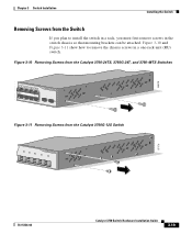
Figure 3-10 Removing Screws from the Catalyst 3750-24TS, 3750G-24T, and 3750-48TS Switches 86819 16 17 18 19 20 21 22 23 24 23X Catalyst 3750 SERIES 1 24X 2 Figure 3-11 Removing Screws from the Switch If you plan to remove the chassis screws in the switch... so that mounting brackets can be attached. Chapter 3 Switch Installation Installing the Switch Removing Screws from the Catalyst 3750G-12S Switch 97170 16 8 9 10 Catalyst 3750 SERIES 11 12 78-15136-02 Catalyst 3750 Switch Hardware Installation Guide 3-19 Figure 3-10 and Figure 3-11 show how to install the switch ...
Figure 3-10 Removing Screws from the Catalyst 3750-24TS, 3750G-24T, and 3750-48TS Switches 86819 16 17 18 19 20 21 22 23 24 23X Catalyst 3750 SERIES 1 24X 2 Figure 3-11 Removing Screws from the Switch If you plan to remove the chassis screws in the switch... so that mounting brackets can be attached. Chapter 3 Switch Installation Installing the Switch Removing Screws from the Catalyst 3750G-12S Switch 97170 16 8 9 10 Catalyst 3750 SERIES 11 12 78-15136-02 Catalyst 3750 Switch Hardware Installation Guide 3-19 Figure 3-10 and Figure 3-11 show how to install the switch ...

Hardware Installation Guide
Page 80
Figure 3-12 Removing Screws from the 3750G-24TS Switch 86820 23 24 23X 24X Catalyst 3750 SERIES 25 26 27 28 Attaching Brackets to remove the chassis screws in a 1.5-RU switch. Follow the same steps to attach the second bracket ...-inch racks, use depend on whether you use part number 700-11523-XX; Installing the Switch Chapter 3 Switch Installation Figure 3-12 shows how to the Catalyst 3750G-24TS Switch The bracket orientation and the brackets that you are attaching the brackets for 24-inch racks, use part number 700-12398-XX. for...
Figure 3-12 Removing Screws from the 3750G-24TS Switch 86820 23 24 23X 24X Catalyst 3750 SERIES 25 26 27 28 Attaching Brackets to remove the chassis screws in a 1.5-RU switch. Follow the same steps to attach the second bracket ...-inch racks, use depend on whether you use part number 700-11523-XX; Installing the Switch Chapter 3 Switch Installation Figure 3-12 shows how to the Catalyst 3750G-24TS Switch The bracket orientation and the brackets that you are attaching the brackets for 24-inch racks, use part number 700-12398-XX. for...

Hardware Installation Guide
Page 88
Installing the Switch Chapter 3 Switch Installation Figure 3-24 Attaching Brackets for 19-Inch Racks to a Catalyst 3750G-12S switch 97171 16 8 9 10 Catalyst 3750 SERIES 11 12 1 1 Phillips truss-head screws Figure 3-25 Attaching Brackets for 24-Inch Telco Racks 9 10 11 12 11X 12X 13 14 13X ...15 16 17 18 19 20 21 22 23 24 23X 14X 24X Catalyst 3750 SERIES 1 2 1 86840 1 Phillips flat-head screws Mounting the Switch in a Rack After the brackets are attached to the switch, use the four supplied number...
Installing the Switch Chapter 3 Switch Installation Figure 3-24 Attaching Brackets for 19-Inch Racks to a Catalyst 3750G-12S switch 97171 16 8 9 10 Catalyst 3750 SERIES 11 12 1 1 Phillips truss-head screws Figure 3-25 Attaching Brackets for 24-Inch Telco Racks 9 10 11 12 11X 12X 13 14 13X ...15 16 17 18 19 20 21 22 23 24 23X 14X 24X Catalyst 3750 SERIES 1 2 1 86840 1 Phillips flat-head screws Mounting the Switch in a Rack After the brackets are attached to the switch, use the four supplied number...
Hardware Installation Guide
Page 89
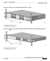
... Figure 3-26 Mounting the Catalyst 3750G-24TS Switch in a Rack Installing the Switch SYST RPS MASTR STAT DUPLX SPEED STACK MODE 12 1X 34 56 78 9 10 11 12 11X 2X 12X 1 13 14 13X 15 16 17 18 19 20 21 22 23 24 23X 14X 24X Catalyst 3750 SERIES 25 26... 27 28 86566 1 Phillips machine screws Figure 3-27 Mounting the Catalyst 3750-24TS, 3750G-24T, 3750G-12S, and 3750-48TS Switches in a Rack SYST RPS MASTR STAT DUPLX SPYESETD SRTPASCK MODE MASTR...
... Figure 3-26 Mounting the Catalyst 3750G-24TS Switch in a Rack Installing the Switch SYST RPS MASTR STAT DUPLX SPEED STACK MODE 12 1X 34 56 78 9 10 11 12 11X 2X 12X 1 13 14 13X 15 16 17 18 19 20 21 22 23 24 23X 14X 24X Catalyst 3750 SERIES 25 26... 27 28 86566 1 Phillips machine screws Figure 3-27 Mounting the Catalyst 3750-24TS, 3750G-24T, 3750G-12S, and 3750-48TS Switches in a Rack SYST RPS MASTR STAT DUPLX SPYESETD SRTPASCK MODE MASTR...

Hardware Installation Guide
Page 92
... Chapter 3 Switch Installation Wall Mounting To install the switch on a Wall, page 3-34 Note The illustrations in this section show the Catalyst 3750G-24TS switch as an example. All the Catalyst 3750 switches are wall-mounted following the same procedures. Figure 3-30 Attaching the 19-inch Brackets for Wall-Mounting Figure 3-30 shows... instructions in these procedures: • Attaching the Brackets to the opposite side. Attaching the Brackets to the Switch for Wall-Mounting 23 24 23X 24X Catalyst 3750 SERIES 25 26 27 28 1 Phillips truss-head screws 3-32...
... Chapter 3 Switch Installation Wall Mounting To install the switch on a Wall, page 3-34 Note The illustrations in this section show the Catalyst 3750G-24TS switch as an example. All the Catalyst 3750 switches are wall-mounted following the same procedures. Figure 3-30 Attaching the 19-inch Brackets for Wall-Mounting Figure 3-30 shows... instructions in these procedures: • Attaching the Brackets to the opposite side. Attaching the Brackets to the Switch for Wall-Mounting 23 24 23X 24X Catalyst 3750 SERIES 25 26 27 28 1 Phillips truss-head screws 3-32...
Hardware Installation Guide
Page 93
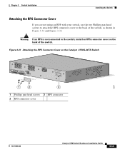
...the two Phillips pan-head screws to attach the RPS connector cover to the switch, install an RPS connector cover on the Catalyst 3750G-24TS Switch 86571 STACK 1 STACK 2 CONSOLE [email protected] 1 2 3 1 Phillips pan-head screws 3 RPS connector 2 RPS ...connector cover 78-15136-02 Catalyst 3750 Switch Hardware Installation Guide 3-33 Figure 3-31 Attaching the RPS Connector Cover on the back of the switch, as shown in Figure...
...the two Phillips pan-head screws to attach the RPS connector cover to the switch, install an RPS connector cover on the Catalyst 3750G-24TS Switch 86571 STACK 1 STACK 2 CONSOLE [email protected] 1 2 3 1 Phillips pan-head screws 3 RPS connector 2 RPS ...connector cover 78-15136-02 Catalyst 3750 Switch Hardware Installation Guide 3-33 Figure 3-31 Attaching the RPS Connector Cover on the back of the switch, as shown in Figure...
Hardware Installation Guide
Page 94
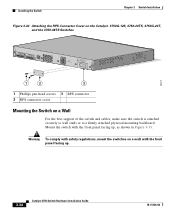
Installing the Switch Chapter 3 Switch Installation Figure 3-32 Attaching the RPS Connector Cover on the Catalyst 3750G-12S, 3750-24TS, 3750G-24T, and the 3750-48TS Switches STACK 1 STACK 2 CONSOLE 1.6A-100R>09A-A2T0,IN05GV0-~60 HZ [email protected] 1 2 3 1 Phillips pan-head screws 3 RPS ... switch is attached securely to wall studs or to a firmly attached plywood mounting backboard. Warning To comply with the front panel facing up . 86572 3-34 Catalyst 3750 Switch Hardware Installation Guide 78-15136-02
Installing the Switch Chapter 3 Switch Installation Figure 3-32 Attaching the RPS Connector Cover on the Catalyst 3750G-12S, 3750-24TS, 3750G-24T, and the 3750-48TS Switches STACK 1 STACK 2 CONSOLE 1.6A-100R>09A-A2T0,IN05GV0-~60 HZ [email protected] 1 2 3 1 Phillips pan-head screws 3 RPS ... switch is attached securely to wall studs or to a firmly attached plywood mounting backboard. Warning To comply with the front panel facing up . 86572 3-34 Catalyst 3750 Switch Hardware Installation Guide 78-15136-02

Hardware Installation Guide
Page 119
Table A-1 Specifications for the Catalyst 3750G-12S Switch Environmental Ranges Operating temperature Storage temperature Relative humidity Operating altitude Storage altitude Power Requirements AC input voltage DC input voltages for RPS ... m) 100 to 240 VAC (autoranging) 1.2A/0.6A, 50 to 60 Hz +12V @13A +12V @13A 120 W, 409 BTUs per hour 0.120 kVA 78-15136-02 Catalyst 3750 Switch Hardware Installation Guide A-1 A A P P E N D I X Technical Specifications This appendix lists the switch technical specifications in Table A-2, Table A-3, Table A-4, Table A-5, and the regulatory agency ...
Table A-1 Specifications for the Catalyst 3750G-12S Switch Environmental Ranges Operating temperature Storage temperature Relative humidity Operating altitude Storage altitude Power Requirements AC input voltage DC input voltages for RPS ... m) 100 to 240 VAC (autoranging) 1.2A/0.6A, 50 to 60 Hz +12V @13A +12V @13A 120 W, 409 BTUs per hour 0.120 kVA 78-15136-02 Catalyst 3750 Switch Hardware Installation Guide A-1 A A P P E N D I X Technical Specifications This appendix lists the switch technical specifications in Table A-2, Table A-3, Table A-4, Table A-5, and the regulatory agency ...