Quick Install Guide 2
Page 3
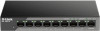
...Solid green Blinking green Off Solid amber Off Description There is powered on. No link 1 2 Figure 3 # Item Description 1 Switch GND This is used to connect the power cable to the User Manual. The total PoE power consumption is still below the 223 W Guard Band ... used to connect the switch to ground. 2 Power Input This is an active link negotiated at 10/100 Mbps on the port at 10/100/1000 Mbps. Package Contents This DSS-100E-18P package should include the following items: • 1 x DSS-100E-18P 5 15 • 1 x Power cord 6 26 7 37 8 48 •...
...Solid green Blinking green Off Solid amber Off Description There is powered on. No link 1 2 Figure 3 # Item Description 1 Switch GND This is used to connect the power cable to the User Manual. The total PoE power consumption is still below the 223 W Guard Band ... used to connect the switch to ground. 2 Power Input This is an active link negotiated at 10/100 Mbps on the port at 10/100/1000 Mbps. Package Contents This DSS-100E-18P package should include the following items: • 1 x DSS-100E-18P 5 15 • 1 x Power cord 6 26 7 37 8 48 •...
Quick Install Guide 2
Page 4
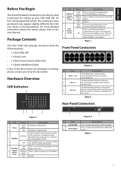
... 10 cm of space to the left and righthand side of them using the provided screws. Refer to the technical specifications in the user manual for ventilation. • Visually inspect the power connector and make sure that were provided with each corner on the bottom panel of the DSS100E...Observe the following precautions to help prevent shutdowns, equipment failures, and personal injury: • Install the DSS-100E-18P in a Rack The DSS-100E-18P can be placed on the 9 10 11 12 13 14 15 16 17 18 1000 Link / Act bottom of the device to the power cord. • Do not stack any devices ...
... 10 cm of space to the left and righthand side of them using the provided screws. Refer to the technical specifications in the user manual for ventilation. • Visually inspect the power connector and make sure that were provided with each corner on the bottom panel of the DSS100E...Observe the following precautions to help prevent shutdowns, equipment failures, and personal injury: • Install the DSS-100E-18P in a Rack The DSS-100E-18P can be placed on the 9 10 11 12 13 14 15 16 17 18 1000 Link / Act bottom of the device to the power cord. • Do not stack any devices ...
Quick Install Guide 3
Page 2
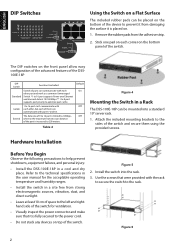
...to the User Manual. Table 2 Rear Panel Connectors 1 2 Figure 3 # Item Description 1 Switch GND This is used to connect the power cable to ground. 2 Power Input This is below the total budget of the above items are damaged or missing, 5 15 please contact your DSS-100E-18P 18Port Unmanaged PoE ... connected to PD error or power budget is not enough.) Table 1 Note: The LED behavior for setting up your local D-Link res6 eller.2 6 7 37 8 48 Hardware Overview # LED Link/Act/ 4 Speed (Ports 17 to 18) PoE 5 (Ports 1 to 16) Status Solid green Blinking green Off Solid ...
...to the User Manual. Table 2 Rear Panel Connectors 1 2 Figure 3 # Item Description 1 Switch GND This is used to connect the power cable to ground. 2 Power Input This is below the total budget of the above items are damaged or missing, 5 15 please contact your DSS-100E-18P 18Port Unmanaged PoE ... connected to PD error or power budget is not enough.) Table 1 Note: The LED behavior for setting up your local D-Link res6 eller.2 6 7 37 8 48 Hardware Overview # LED Link/Act/ 4 Speed (Ports 17 to 18) PoE 5 (Ports 1 to 16) Status Solid green Blinking green Off Solid ...
Quick Install Guide 3
Page 3
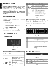
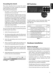
...8226; Visually inspect the power connector and make sure that the ground connections on the switch. Refer to the technical specifications in the user manual for the acceptable operating temperature and humidity ranges. • Install the switch in a site free from strong electromagnetic sources, vibration, dust.... ENGLISH Grounding the Switch This section describes how to connect the switch to help prevent shutdowns, equipment failures, and personal injury: • Install the DSS-100E-18P in a cool and dry place. DIP Switches 5 6 7 85 6 7 8 15 26 37 48 1 5 26 37 48 The DIP switches...
...8226; Visually inspect the power connector and make sure that the ground connections on the switch. Refer to the technical specifications in the user manual for the acceptable operating temperature and humidity ranges. • Install the switch in a site free from strong electromagnetic sources, vibration, dust.... ENGLISH Grounding the Switch This section describes how to connect the switch to help prevent shutdowns, equipment failures, and personal injury: • Install the DSS-100E-18P in a cool and dry place. DIP Switches 5 6 7 85 6 7 8 15 26 37 48 1 5 26 37 48 The DIP switches...

