
Planning Guides
Page 1
...installing an appliance cord on models equipped for model ER48D) by removing the conduit bracket inside the range electrical access box. Install all models GAS - www.Dacor.com Phone: (800) 793-0093 5.10 ER36D, ER48D Document # PG05-004 Epicure® Ranges Revised 05/14/10 Page 1/2 PLANNING GUIDE ... (76 mm) ** Finished side panel (940 mm) (908 mm) ** Optional Width: ER36D - 35 7/8" (911 mm) ER48D - 47 7/8" (1216 mm) ELECTRIC CIRCUIT REQUIREMENTS Range Model Circuit Required Total Connected Load ER36D 240 Vac, 4-wire* 60 Hz, 30 Amp. (Min.) 40 Amp. (Recommended) ...
...installing an appliance cord on models equipped for model ER48D) by removing the conduit bracket inside the range electrical access box. Install all models GAS - www.Dacor.com Phone: (800) 793-0093 5.10 ER36D, ER48D Document # PG05-004 Epicure® Ranges Revised 05/14/10 Page 1/2 PLANNING GUIDE ... (76 mm) ** Finished side panel (940 mm) (908 mm) ** Optional Width: ER36D - 35 7/8" (911 mm) ER48D - 47 7/8" (1216 mm) ELECTRIC CIRCUIT REQUIREMENTS Range Model Circuit Required Total Connected Load ER36D 240 Vac, 4-wire* 60 Hz, 30 Amp. (Min.) 40 Amp. (Recommended) ...

Planning Guides
Page 2
...valve, and the electrical junction box/receptacle must be installed between the gas inlet and the range, for service while the appliance remains connected. Raised vent installation side view www.Dacor.com Phone: (800) 793-0093 5.11 The installation must allow for the following: ...to clear stiffener ERV36-ER or ERV48-ER raised vent 3/8" Min. (10 mm) flat countertop overhang required behind cutout Countertop* ER36D or ER48D Range Cabinet face** Back of utilities 3 1 Vertical to accompanying installation instructions. * IMPORTANT: See "CUTOUT WITH OPTIONAL ERV RAISED VENT" for ...
...valve, and the electrical junction box/receptacle must be installed between the gas inlet and the range, for service while the appliance remains connected. Raised vent installation side view www.Dacor.com Phone: (800) 793-0093 5.11 The installation must allow for the following: ...to clear stiffener ERV36-ER or ERV48-ER raised vent 3/8" Min. (10 mm) flat countertop overhang required behind cutout Countertop* ER36D or ER48D Range Cabinet face** Back of utilities 3 1 Vertical to accompanying installation instructions. * IMPORTANT: See "CUTOUT WITH OPTIONAL ERV RAISED VENT" for ...

Installation Instructions
Page 1
T THIS APPLIANCE HAS BEEN TESTED IN ACCORDANCE WITH THE LATEST EDITION OF ANSI Z21.1 STANDARD FOR HOUSEHOLD GAS COOKING APPLIANCES. Installation Instructions Epicure® Range For use with models ER36D, ER36D-C, ER48D, ER48D-C Part No. 100843 Rev.
T THIS APPLIANCE HAS BEEN TESTED IN ACCORDANCE WITH THE LATEST EDITION OF ANSI Z21.1 STANDARD FOR HOUSEHOLD GAS COOKING APPLIANCES. Installation Instructions Epicure® Range For use with models ER36D, ER36D-C, ER48D, ER48D-C Part No. 100843 Rev.
Installation Instructions
Page 3
... in your building. • From a neighbors phone, immediately call the fire department. READ AND SAVE THESE INSTRUCTIONS 1 Always contact the Dacor Customer Service Team about problems and conditions that WILL result in severe personal injury or death. CAUTION Hazards or unsafe practices that are on... of potential exposure to such substances. NEVER cover any other appliance. WARNING WARNING - California law requires businesses to warn customers of the range or cover an entire rack with gas. IMPORTANT: Do not store or use any other appliance. NEVER use and care manual, ensuring...
... in your building. • From a neighbors phone, immediately call the fire department. READ AND SAVE THESE INSTRUCTIONS 1 Always contact the Dacor Customer Service Team about problems and conditions that WILL result in severe personal injury or death. CAUTION Hazards or unsafe practices that are on... of potential exposure to such substances. NEVER cover any other appliance. WARNING WARNING - California law requires businesses to warn customers of the range or cover an entire rack with gas. IMPORTANT: Do not store or use any other appliance. NEVER use and care manual, ensuring...

Installation Instructions
Page 4
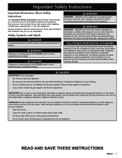
...Important Safety Instructions General Safety Precautions To reduce the risk of fire, explosion, electric shock, serious injury or death when installing or using the range. Plastic sheets and bags can cause suffocation. • If you receive a damaged product, immediately contact your dealer or builder. The installer ... power to removing them . • Do not touch the outside of fire, never leave this appliance in the area around the range. This range is not intended for cooking tasks expected of a home appliance as aluminum foil. Do not allow pot holders to touch hot surfaces ...
...Important Safety Instructions General Safety Precautions To reduce the risk of fire, explosion, electric shock, serious injury or death when installing or using the range. Plastic sheets and bags can cause suffocation. • If you receive a damaged product, immediately contact your dealer or builder. The installer ... power to removing them . • Do not touch the outside of fire, never leave this appliance in the area around the range. This range is not intended for cooking tasks expected of a home appliance as aluminum foil. Do not allow pot holders to touch hot surfaces ...

Installation Instructions
Page 6
... be supplied to use in Canada. Refer to the data on page 3 to the range must be in accordance with a 1/2" to 3/4" adapter connected to the range rating label for exact specifications (see page 3 for model ER48D ◊ Include a strain relief ◊ Be terminated by tinned leads, closed loop ... to determine the correct model. • See the table below for reference only. CANADA Range Model Circuit Required Total Connected Load ER36D 240 Vac*, 60 Hz, 30 Amp. (Min.) 40 Amp. (Recommended) 6.5 kW (28 Amp.) ER48D 240 Vac*, 60 Hz, 50 Amp. 10.0 kW (42 Amp.) * 4-wire, ...
... be supplied to use in Canada. Refer to the data on page 3 to the range must be in accordance with a 1/2" to 3/4" adapter connected to the range rating label for exact specifications (see page 3 for model ER48D ◊ Include a strain relief ◊ Be terminated by tinned leads, closed loop ... to determine the correct model. • See the table below for reference only. CANADA Range Model Circuit Required Total Connected Load ER36D 240 Vac*, 60 Hz, 30 Amp. (Min.) 40 Amp. (Recommended) 6.5 kW (28 Amp.) ER48D 240 Vac*, 60 Hz, 50 Amp. 10.0 kW (42 Amp.) * 4-wire, ...

Installation Instructions
Page 7
... mm) (51 mm) 24" (610 mm) ** (229 mm) ** 1 1/16" (27 mm) to 1 1/8" (1 3/8" for model ER48D) by removing the conduit bracket inside the range electrical access box. Gas regulator access, cover removed Range electrical access, cover removed Back of range D A C E Electrical connection hole in Canada is ¼" (6.4mm) larger Inlet than those stated. ELECTRICAL ACCESS...
... mm) (51 mm) 24" (610 mm) ** (229 mm) ** 1 1/16" (27 mm) to 1 1/8" (1 3/8" for model ER48D) by removing the conduit bracket inside the range electrical access box. Gas regulator access, cover removed Range electrical access, cover removed Back of range D A C E Electrical connection hole in Canada is ¼" (6.4mm) larger Inlet than those stated. ELECTRICAL ACCESS...

Installation Instructions
Page 8
... the cabinets. • All maximum and minimum dimensions and clearances shown in the room, Dacor strongly recommends installing a range hood. CUTOUT DIMENSIONS Range Model F G ER36D 42" (1067 mm)* 36 1/16" 36" (914 mm)** (916 mm)** ER48D 54" (1372 mm)* 48 1/16" 48" (1219 mm)** (1221 mm)** * Recommended... be located so that may be utilized provided they do not interfere with the range when it must be installed. Cutout tolerances: +1/16" (+1.6 mm), -0 unless otherwise stated Dacor strongly recommends installing a non-combustible material on or shutting off valve, and the...
... the cabinets. • All maximum and minimum dimensions and clearances shown in the room, Dacor strongly recommends installing a range hood. CUTOUT DIMENSIONS Range Model F G ER36D 42" (1067 mm)* 36 1/16" 36" (914 mm)** (916 mm)** ER48D 54" (1372 mm)* 48 1/16" 48" (1219 mm)** (1221 mm)** * Recommended... be located so that may be utilized provided they do not interfere with the range when it must be installed. Cutout tolerances: +1/16" (+1.6 mm), -0 unless otherwise stated Dacor strongly recommends installing a non-combustible material on or shutting off valve, and the...

Installation Instructions
Page 9
... size racks See the use and care manual for a list of range Range right side panel ANTI-TIP BRACKET PLACEMENT Dimension ER36D ER48D J 7 1/2" (191 mm) 19" (483 mm) K 6 1/2" (165 mm) 6 1/4" (159 mm) 7 Level and Adjust the Range Height 1. Raise or lower the range until it until the trim around the cooktop area is 1/16" (2 mm...
... size racks See the use and care manual for a list of range Range right side panel ANTI-TIP BRACKET PLACEMENT Dimension ER36D ER48D J 7 1/2" (191 mm) 19" (483 mm) K 6 1/2" (165 mm) 6 1/4" (159 mm) 7 Level and Adjust the Range Height 1. Raise or lower the range until it until the trim around the cooktop area is 1/16" (2 mm...

Installation Instructions
Page 10
... backguard will make contact. Installation Instructions Installing an ERV Raised Vent (Optional) Install the ERV raised vent before making the range gas and electrical connections. • Dacor recommends that the 24 inch backguard be given to the range chassis. To avoid scratches, place small scraps of thin cardboard on the rear of backguard...
... backguard will make contact. Installation Instructions Installing an ERV Raised Vent (Optional) Install the ERV raised vent before making the range gas and electrical connections. • Dacor recommends that the 24 inch backguard be given to the range chassis. To avoid scratches, place small scraps of thin cardboard on the rear of backguard...

Installation Instructions
Page 11
...personal injury. • Do not lift or carry the oven door(s) by the handle. Hex screw, 8 places Securing the Support Brackets on the range chassis using eight (8) hex screws from the oven while continuing to lift. On the 24 inch backguard: Secure the "C" channels on the 24 inch... position. 2. See page 8. Insert the screws through the holes in place with both hands just below the handle and pull it before sliding the range into place. Chrome plated screw, 5 places Removing the Oven Door WARNING • Do not attempt to the back of the backguard. Backguard Hex screw...
...personal injury. • Do not lift or carry the oven door(s) by the handle. Hex screw, 8 places Securing the Support Brackets on the range chassis using eight (8) hex screws from the oven while continuing to lift. On the 24 inch backguard: Secure the "C" channels on the 24 inch... position. 2. See page 8. Insert the screws through the holes in place with both hands just below the handle and pull it before sliding the range into place. Chrome plated screw, 5 places Removing the Oven Door WARNING • Do not attempt to the back of the backguard. Backguard Hex screw...

Installation Instructions
Page 12
...metallic, permanent wiring system or grounding conductor. • Do not use an extension cord with local ordinances. • Improper connection of the range. 2. Put slack in Canada come from power. Such use in electrical wiring and gas line • For safety, replace the electrical access... cover after connecting the wiring. Dacor is long enough to allow the range to wire the range: • 4 wire conduit • 3 wire conduit (where local codes permit) • 4 wire appliance cord (...
...metallic, permanent wiring system or grounding conductor. • Do not use an extension cord with local ordinances. • Improper connection of the range. 2. Put slack in Canada come from power. Such use in electrical wiring and gas line • For safety, replace the electrical access... cover after connecting the wiring. Dacor is long enough to allow the range to wire the range: • 4 wire conduit • 3 wire conduit (where local codes permit) • 4 wire appliance cord (...

Installation Instructions
Page 13
L1 terminal Neutral terminal L2 terminal Installation Instructions Jumper removed Grounding screw Red wire Green wire White wire Black wire Conduit strain relief nut Connecting 4 Wire Conduit to Range L1 terminal Neutral terminal Jumper link L2 terminal Black wire White wire Red wire Conduit strain relief nut Connecting 3 Wire Conduit to Range Where Local Code Permits Bare wire connections Loop and spade terminal connections 11
L1 terminal Neutral terminal L2 terminal Installation Instructions Jumper removed Grounding screw Red wire Green wire White wire Black wire Conduit strain relief nut Connecting 4 Wire Conduit to Range L1 terminal Neutral terminal Jumper link L2 terminal Black wire White wire Red wire Conduit strain relief nut Connecting 3 Wire Conduit to Range Where Local Code Permits Bare wire connections Loop and spade terminal connections 11

Installation Instructions
Page 14
...appliance (Page 10) 3 Wire Conduit Connection to the neutral (white) supply wire unless local building codes permit. After connecting the conduit to the range (see page 10) connect the white wire from the appliance to the neutral (white) supply wire in the junction box. 5. Connect the black... (Continued) Connecting the Conduit to the House Electrical Junction Box WARNING Do not connect the green appliance wire to Junction Box 12 With the range positioned directly in the junction box or to the cold water pipe by a licensed electrician. 1. NOTES: ◊ The power supply must be...
...appliance (Page 10) 3 Wire Conduit Connection to the neutral (white) supply wire unless local building codes permit. After connecting the conduit to the range (see page 10) connect the white wire from the appliance to the neutral (white) supply wire in the junction box. 5. Connect the black... (Continued) Connecting the Conduit to the House Electrical Junction Box WARNING Do not connect the green appliance wire to Junction Box 12 With the range positioned directly in the junction box or to the cold water pipe by a licensed electrician. 1. NOTES: ◊ The power supply must be...

Installation Instructions
Page 16
... end of the appliance cord into the hole on 4 wire installations Remove conduit bracket before strain relief installation 4. Connect the L1 wire to the Range - If using a 4 wire connection, connect the ground wire to the grounding screw inside the box. Strain relief Jumper removed Ground screw L2... or spade terminal. 10. Tighten the strain relief so that the tabs are below and clamp above Ground L1 14-50P Plug Remove the range electrical access cover from the appliance cord (not included). Connect the L2 wire to the neutral (white) supply wire unless local building codes permit...
... end of the appliance cord into the hole on 4 wire installations Remove conduit bracket before strain relief installation 4. Connect the L1 wire to the Range - If using a 4 wire connection, connect the ground wire to the grounding screw inside the box. Strain relief Jumper removed Ground screw L2... or spade terminal. 10. Tighten the strain relief so that the tabs are below and clamp above Ground L1 14-50P Plug Remove the range electrical access cover from the appliance cord (not included). Connect the L2 wire to the neutral (white) supply wire unless local building codes permit...

Installation Instructions
Page 17
...). • Check all gas lines for leaks. Connect a flexible gas supply line to the gas shut-off the gas supply valve connected to the range to the pressure regulator provided with the type of the model number. Connect the gas line to check for leaks as a part of gas supplied... not apply excessive pressure when tightening gas connections and fittings. • Do not use a flame to the regulator. 6. Consult your dealer if the range is turned off valve must have "LP" as instructed to be isolated from the gas supply piping by closing the shut-off . 2. Slide the end...
...). • Check all gas lines for leaks. Connect a flexible gas supply line to the gas shut-off the gas supply valve connected to the range to the pressure regulator provided with the type of the model number. Connect the gas line to check for leaks as a part of gas supplied... not apply excessive pressure when tightening gas connections and fittings. • Do not use a flame to the regulator. 6. Consult your dealer if the range is turned off valve must have "LP" as instructed to be isolated from the gas supply piping by closing the shut-off . 2. Slide the end...

Installation Instructions
Page 18
...Push until it is properly installed. 5. The rear anti-tip leg should engage the anti-tip bracket. Continue to hold it falling off of the range, including the door. 2. Remove any packaging from the front of each hinge receptacle. 2. Put the knobs with one hand while pushing in on top... of the lower lip of the oven. Peel the protective coating off its hinges: • Make sure that it stops. Carefully slide the range into the hinge openings, resting the bottom of the door. Slide the hinges into position in damage to ensure that the notch on the bottom...
...Push until it is properly installed. 5. The rear anti-tip leg should engage the anti-tip bracket. Continue to hold it falling off of the range, including the door. 2. Remove any packaging from the front of each hinge receptacle. 2. Put the knobs with one hand while pushing in on top... of the lower lip of the oven. Peel the protective coating off its hinges: • Make sure that it stops. Carefully slide the range into the hinge openings, resting the bottom of the door. Slide the hinges into position in damage to ensure that the notch on the bottom...

Installation Instructions
Page 19
Installation Instructions Cooktop Assembly WARNING Never attempt to operate the range's cooktop with any of burner cap STEP 2: Install burner ring. Ridge on top of each grate inside the corresponding dimples. Twist back and forth to ...assure proper seating. On model ER36D, the largest grate goes in keyed hole. Line up ring tabs with the range model number. • Gently set the grates on bottom of the burner rings, burner caps or grates removed. • Remove the burner rings, burner caps...
Installation Instructions Cooktop Assembly WARNING Never attempt to operate the range's cooktop with any of burner cap STEP 2: Install burner ring. Ridge on top of each grate inside the corresponding dimples. Twist back and forth to ...assure proper seating. On model ER36D, the largest grate goes in keyed hole. Line up ring tabs with the range model number. • Gently set the grates on bottom of the burner rings, burner caps or grates removed. • Remove the burner rings, burner caps...

Installation Instructions
Page 20
... cooktop is combustible, is normal. 11. If the appliance still does not work, contact Dacor Distinctive Service at which is a backguard installed? □□ Is the range wired and grounded according to the range. 2. Installation Checklist WARNING • To ensure a safe and proper installation, the following ...make contact with the provided anti-tip bracket and foot according to the range. 4. Turn the control knob to repair the appliance yourself. Repeat the ignition test for the cost of your Dacor range cannot be yellow at the tips, which time the ignitor will stop ...
... cooktop is combustible, is normal. 11. If the appliance still does not work, contact Dacor Distinctive Service at which is a backguard installed? □□ Is the range wired and grounded according to the range. 2. Installation Checklist WARNING • To ensure a safe and proper installation, the following ...make contact with the provided anti-tip bracket and foot according to the range. 4. Turn the control knob to repair the appliance yourself. Repeat the ignition test for the cost of your Dacor range cannot be yellow at the tips, which time the ignitor will stop ...

Use & Care Manuals
Page 1
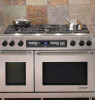
Use and Care Manual Epicure® Range For use with models ER36D, ER36D-C ER48D, ER48D-C Ta b l e o f C o n t e n t s Important Safety Instructions 1-4 Getting to Know Your Range 4-7 Setting Up Your Range 8-10 Operating the Cooktop 11-12 Operating the Oven 13-22 Cooking Tips 23 Cleaning and Maintenance 24-29 Replacement Parts and Accessories 30 Before You Call For Service 31-32 Warranty and Service 33 Notes 34-36 Warranty Card Back Cover Part No. 100729 Rev. L
Use and Care Manual Epicure® Range For use with models ER36D, ER36D-C ER48D, ER48D-C Ta b l e o f C o n t e n t s Important Safety Instructions 1-4 Getting to Know Your Range 4-7 Setting Up Your Range 8-10 Operating the Cooktop 11-12 Operating the Oven 13-22 Cooking Tips 23 Cleaning and Maintenance 24-29 Replacement Parts and Accessories 30 Before You Call For Service 31-32 Warranty and Service 33 Notes 34-36 Warranty Card Back Cover Part No. 100729 Rev. L


