Planning Guides
Page 1
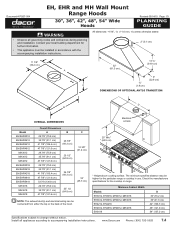
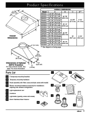
...during planning and installation. The minimum specified distance may be installed in use. Minimum Cabinet Width Models EH3012, EH3018, MH3012, MH3018 EH3612, EH3618, MH3612, MH3618 EH4212, EH4218 EH4812, EH4818, MH4812, MH4818 EH5418 D 30" (76.2 cm) 36" (91.5 cm) 42" (106.7 cm) 48" (...instructions. Document # PG07-004 EH, EHR and MH Wall Mount Range Hoods 30", 36", 42", 48", 54" Wide Hoods Revised 05/14/10 Page 1/3 PLANNING GUIDE warning • Observe all appliances according to change without notice. www.Dacor.com Phone: (800) 793-0093 7.4 All tolerances: +1/16", -0, ...
...during planning and installation. The minimum specified distance may be installed in use. Minimum Cabinet Width Models EH3012, EH3018, MH3012, MH3018 EH3612, EH3618, MH3612, MH3618 EH4212, EH4218 EH4812, EH4818, MH4812, MH4818 EH5418 D 30" (76.2 cm) 36" (91.5 cm) 42" (106.7 cm) 48" (...instructions. Document # PG07-004 EH, EHR and MH Wall Mount Range Hoods 30", 36", 42", 48", 54" Wide Hoods Revised 05/14/10 Page 1/3 PLANNING GUIDE warning • Observe all appliances according to change without notice. www.Dacor.com Phone: (800) 793-0093 7.4 All tolerances: +1/16", -0, ...

Planning Guides
Page 2
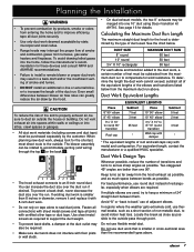
...Models Weight EH3012, MH3012 48 lbs. (22 kg) EH3018, MH3018, EH3612, MH3612 53 lbs. (24 kg) EH3618, MH3618 57 lbs. (26 kg) EH4212 55 lbs. (25 kg) EH4218 60 lbs. (27 kg) EH4812, MH4812 70 lbs...calculate the actual length the duct work cannot exceed. Max. Specifications subject to change without notice. www.Dacor.com Phone: (800) 793-0093 7.5 surge) 120 Vac, 75 W halogen 120 Vac, 15 Amp...Duct Planning Guide or see the hood installation instructions. Document # PG07-004 EH, EHR and MH Wall Mount Range Hoods 30", 36", 42", 48", 54" Wide Hoods Revised 05/14/10 Page 2/3...
...Models Weight EH3012, MH3012 48 lbs. (22 kg) EH3018, MH3018, EH3612, MH3612 53 lbs. (24 kg) EH3618, MH3618 57 lbs. (26 kg) EH4212 55 lbs. (25 kg) EH4218 60 lbs. (27 kg) EH4812, MH4812 70 lbs...calculate the actual length the duct work cannot exceed. Max. Specifications subject to change without notice. www.Dacor.com Phone: (800) 793-0093 7.5 surge) 120 Vac, 75 W halogen 120 Vac, 15 Amp...Duct Planning Guide or see the hood installation instructions. Document # PG07-004 EH, EHR and MH Wall Mount Range Hoods 30", 36", 42", 48", 54" Wide Hoods Revised 05/14/10 Page 2/3...

Planning Guides
Page 3
... cm) CL 9 7/8" (25.1 cm) Electrical access holes 7/8" Dia. (5.1 cm) CL 6 1/8" (15.6 cm) E*** Bottom of the hood. Install all appliances according to change without notice. www.Dacor.com Phone: (800) 793-0093 7.6 All tolerances: +1/16", -0, (+1.6 mm, -0) unless otherwise stated. Document # PG07-004 EH, EHR and... MH Wall Mount Range Hoods 30", 36", 42", 48", 54" Wide Hoods Revised 05/14/10 Page 3/3 PLANNING...
... cm) CL 9 7/8" (25.1 cm) Electrical access holes 7/8" Dia. (5.1 cm) CL 6 1/8" (15.6 cm) E*** Bottom of the hood. Install all appliances according to change without notice. www.Dacor.com Phone: (800) 793-0093 7.6 All tolerances: +1/16", -0, (+1.6 mm, -0) unless otherwise stated. Document # PG07-004 EH, EHR and... MH Wall Mount Range Hoods 30", 36", 42", 48", 54" Wide Hoods Revised 05/14/10 Page 3/3 PLANNING...
Installation Instructions
Page 1
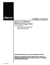
Tested in accordance with models: EH30, EH36, EH42, EH48, EH54, MH30, MH36 and MH48 Part No. 102139 Rev. Installation Instructions Epicure® and Millennia® Wall Mount Range Hoods For use with all dacor® ranges and cooktops. J Approved for use with the latest edition of ANSI/UL 507 standard for electric fans and can/csa-c22.2 no. 113 standard for fans and ventilators.
Tested in accordance with models: EH30, EH36, EH42, EH48, EH54, MH30, MH36 and MH48 Part No. 102139 Rev. Installation Instructions Epicure® and Millennia® Wall Mount Range Hoods For use with all dacor® ranges and cooktops. J Approved for use with the latest edition of ANSI/UL 507 standard for electric fans and can/csa-c22.2 no. 113 standard for fans and ventilators.

Installation Instructions
Page 2
... or the Dacor Customer Service Team. Friday 6:00 a.m. Pacific Time Appliance Data Plate • The appliance data plate contains the model and serial number information and the electrical requirements. • It is located inside the hood behind the filters on the appliance data plate. ...Remove the filters to view it. Friday 6:00 a.m. For repairs to Dacor appliances under warranty only) Phone: (877) 337-3226 Monday - Table of...
... or the Dacor Customer Service Team. Friday 6:00 a.m. Pacific Time Appliance Data Plate • The appliance data plate contains the model and serial number information and the electrical requirements. • It is located inside the hood behind the filters on the appliance data plate. ...Remove the filters to view it. Friday 6:00 a.m. For repairs to Dacor appliances under warranty only) Phone: (877) 337-3226 Monday - Table of...
Installation Instructions
Page 3
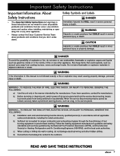
...OF FIRE, ELECTRIC SHOCK, OR INJURY TO PERSONS, OBSERVE THE FOLLOWING: a) Use this or any other appliance. • Always contact the Dacor Customer Service Team about problems and conditions that can occur. b) Before servicing or cleaning unit, switch power off at service panel and lock the... service disconnecting means to the outdoors. When the service disconnecting means cannot be vented to prevent power from cooktop burners, ovens and range hoods. b) Sufficient air is not followed exactly, a fire or explosion may result causing property damage, personal injury or death. Do not ...
...OF FIRE, ELECTRIC SHOCK, OR INJURY TO PERSONS, OBSERVE THE FOLLOWING: a) Use this or any other appliance. • Always contact the Dacor Customer Service Team about problems and conditions that can occur. b) Before servicing or cleaning unit, switch power off at service panel and lock the... service disconnecting means to the outdoors. When the service disconnecting means cannot be vented to prevent power from cooktop burners, ovens and range hoods. b) Sufficient air is not followed exactly, a fire or explosion may result causing property damage, personal injury or death. Do not ...

Installation Instructions
Page 4
...the cooktop, range or range hood. • The minimum vertical distance between the cooktop surface and the exterior part of fire, electric shock, serious injury or death when using the appliance. If the product is not working properly. Contact the nearest Dacor authorized service representative at (800)...other window coverings that the customer knows where and how to turn the power off. • Before installing or servicing the range hood, switch power off at www.Dacor.com for the minimum and maximum vertical distance from children. General Safety Precautions To reduce the risk of the...
...the cooktop, range or range hood. • The minimum vertical distance between the cooktop surface and the exterior part of fire, electric shock, serious injury or death when using the appliance. If the product is not working properly. Contact the nearest Dacor authorized service representative at (800)...other window coverings that the customer knows where and how to turn the power off. • Before installing or servicing the range hood, switch power off at www.Dacor.com for the minimum and maximum vertical distance from children. General Safety Precautions To reduce the risk of the...

Installation Instructions
Page 6
Single exhaust models** Standard 8" duct connection Dual exhaust models* Standard 8" duct connection Front of hood Electrical access holes 7/8" Dia. (5.1 cm) 1 ½" (3.8 cm) 4" (10.2 cm) 3" (7.6 cm) 3" (7.6 cm) 4" (10.2 cm) ¾" (1.9 cm) Electrical access holes 7/8" Dia. (5.1 cm...50.2 cm CL 9 7/8" (25.1 cm) 6 1/8" (15.6 cm) D *** Bottom of the hood. NOTE: The exhaust duct(s) and electrical wiring can be connected from either the top or the back of hood Dual exhaust models* Standard 8" duct connection Single exhaust models** Standard 8" duct connection Back Dimensions * Models...
Single exhaust models** Standard 8" duct connection Dual exhaust models* Standard 8" duct connection Front of hood Electrical access holes 7/8" Dia. (5.1 cm) 1 ½" (3.8 cm) 4" (10.2 cm) 3" (7.6 cm) 3" (7.6 cm) 4" (10.2 cm) ¾" (1.9 cm) Electrical access holes 7/8" Dia. (5.1 cm...50.2 cm CL 9 7/8" (25.1 cm) 6 1/8" (15.6 cm) D *** Bottom of the hood. NOTE: The exhaust duct(s) and electrical wiring can be connected from either the top or the back of hood Dual exhaust models* Standard 8" duct connection Single exhaust models** Standard 8" duct connection Back Dimensions * Models...
Installation Instructions
Page 7
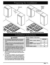
...91.1 cm) 41 7/8" (106.4 cm) 26 7/8" (68.3 cm) 47 7/8" (121.6 cm) 53 7/8 (136.8 cm) 18" (45.7 cm) 6 1/8" (15.6 cm) MH3018 MH3618 MH4818 29 7/8" (75.9 cm) 35 7/8" (91.1 cm) 25 1/2" (64.8 cm) 47 7/8" (121.6 cm) *** See diagram on facing page. 32" (81.3 cm) 13 &#...information 9" (22.9 cm) ¾" (1.9 cm) Parts List C •A 2 temporary mounting brackets • B Temporary mounting hardware • C Hood assembly with filters (size and style varies with model) •D Blower mounting hardware (used only for installations E requiring rear exhaust configuration • E ...
...91.1 cm) 41 7/8" (106.4 cm) 26 7/8" (68.3 cm) 47 7/8" (121.6 cm) 53 7/8 (136.8 cm) 18" (45.7 cm) 6 1/8" (15.6 cm) MH3018 MH3618 MH4818 29 7/8" (75.9 cm) 35 7/8" (91.1 cm) 25 1/2" (64.8 cm) 47 7/8" (121.6 cm) *** See diagram on facing page. 32" (81.3 cm) 13 &#...information 9" (22.9 cm) ¾" (1.9 cm) Parts List C •A 2 temporary mounting brackets • B Temporary mounting hardware • C Hood assembly with filters (size and style varies with model) •D Blower mounting hardware (used only for installations E requiring rear exhaust configuration • E ...

Installation Instructions
Page 8
...white) power supply wire. • Do not install a fuse in the selected location. The minimum specified distance may be obtained from the hood to a dedicated three wire grounded, single phase circuit rated at 120 Vac 60 Hz, 15 Amp. 6 Power Supply warning The electric service ... directly above the range should be installed. E Electrical access 25" Min. (63.5 cm) MINIMUM CABINET WIDTH Models E EH3012, EH3018, MH3012, MH3018 EH3612, EH3618, MH3612, MH3618 30" (76.2 cm) 36" (91.5 cm) EH4212, EH4218 42" (106.7 cm) EH4812, EH4818, MH4812, MH4818 EH5418 48" (121.9 cm) 54" (137.2...
...white) power supply wire. • Do not install a fuse in the selected location. The minimum specified distance may be obtained from the hood to a dedicated three wire grounded, single phase circuit rated at 120 Vac 60 Hz, 15 Amp. 6 Power Supply warning The electric service ... directly above the range should be installed. E Electrical access 25" Min. (63.5 cm) MINIMUM CABINET WIDTH Models E EH3012, EH3018, MH3012, MH3018 EH3612, EH3618, MH3612, MH3618 30" (76.2 cm) 36" (91.5 cm) EH4212, EH4218 42" (106.7 cm) EH4812, EH4818, MH4812, MH4818 EH5418 48" (121.9 cm) 54" (137.2...
Installation Instructions
Page 9
...• Make sure duct work does not interfere with 8-inch duct work materials (including screws and duct tape) must be purchased separately by the hood. For best performance, use round duct instead of 24" straight duct between them. Locate the break as close as possible. Do not use of ...and/or the insufficient venting of smoke and fumes. • DO NOT install an additional in cross-sectional area than one 10" duct using Dacor transition kit AHT10. CAUTION To reduce the risk of the duct run to accommodate venting (and wiring) through point. See page 16 for wind...
...• Make sure duct work does not interfere with 8-inch duct work materials (including screws and duct tape) must be purchased separately by the hood. For best performance, use round duct instead of 24" straight duct between them. Locate the break as close as possible. Do not use of ...and/or the insufficient venting of smoke and fumes. • DO NOT install an additional in cross-sectional area than one 10" duct using Dacor transition kit AHT10. CAUTION To reduce the risk of the duct run to accommodate venting (and wiring) through point. See page 16 for wind...

Installation Instructions
Page 10
... provided with the mounting holes in the wall or cabinet as necessary to allow the wiring to pass through the back of the hood, use the top dimensions to a drywall or plastered surface, install a reinforced mounting block between the cabinets at the installation location ...included according to the studs and cabinets if they line up the mounting brackets during site preparation and installation. If mounting the hood to the range hood should be located. Do not install a damaged or incomplete appliance. Mounting Location Preparation warning • The electrical service to brick...
... provided with the mounting holes in the wall or cabinet as necessary to allow the wiring to pass through the back of the hood, use the top dimensions to a drywall or plastered surface, install a reinforced mounting block between the cabinets at the installation location ...included according to the studs and cabinets if they line up the mounting brackets during site preparation and installation. If mounting the hood to the range hood should be located. Do not install a damaged or incomplete appliance. Mounting Location Preparation warning • The electrical service to brick...
Installation Instructions
Page 11
... electrical service provided meets the range hood specifications. • Observe all governing codes and ordinances during installation. Contact your local building department for further information. • A qualified technician must be damaged. 2. Blower Rotation Instructions MODEL EH3012, MH3012, EH3612, MH3612, EH4212 EH4812, MH4812 EH3018, MH3018, EH3618, MH3618, EH4218 EH4818, MH4818, EH5418 SEE PAGE...
... electrical service provided meets the range hood specifications. • Observe all governing codes and ordinances during installation. Contact your local building department for further information. • A qualified technician must be damaged. 2. Blower Rotation Instructions MODEL EH3012, MH3012, EH3612, MH3612, EH4212 EH4812, MH4812 EH3018, MH3018, EH3618, MH3618, EH4218 EH4818, MH4818, EH5418 SEE PAGE...

Installation Instructions
Page 12
... the blower from below . 7. Remove cable clamp Wiring Harness Remove cable ties Rear mounting plate 10 Remove the filters from the top of the hood. 8. Remove and save the nut that holds the wiring harness cable clamp in place. It is located behind the panel on the right side... inside the hood, on its back with a single blower) 1. Attach the mounting plate removed in step 11 (rear mounting plate) to the blower motor. Installation ...
... the blower from below . 7. Remove cable clamp Wiring Harness Remove cable ties Rear mounting plate 10 Remove the filters from the top of the hood. 8. Remove and save the nut that holds the wiring harness cable clamp in place. It is located behind the panel on the right side... inside the hood, on its back with a single blower) 1. Attach the mounting plate removed in step 11 (rear mounting plate) to the blower motor. Installation ...

Installation Instructions
Page 13
...side using two (2) supplied cable ties. 16. Connector location 14. Securing any remaining slack that cover the holes on the back of the hood. See below . 15. Route the wiring harness as shown. Installation Instructions 13. Insert the opening on the blower motor assembly into the hole... inside the hood, on a large flat surface.1. 2. Using existing screws, attach the cover plate removed in step 2 to take up . Attach the wiring harness ...
...side using two (2) supplied cable ties. 16. Connector location 14. Securing any remaining slack that cover the holes on the back of the hood. See below . 15. Route the wiring harness as shown. Installation Instructions 13. Insert the opening on the blower motor assembly into the hole... inside the hood, on a large flat surface.1. 2. Using existing screws, attach the cover plate removed in step 2 to take up . Attach the wiring harness ...

Installation Instructions
Page 14
...rear mounting plate) to both wiring harness connectors from below, remove the four (4) nuts that hold the wiring harness to the brace inside the hood, on its back with four (4) nuts each blower from the blower motors. 9. Disconnect both blower motors. The connector on the right side... inside the back of the hood. Connector locations 12 Cut the cable tie that hold the blower and mounting plates in place and remove. Remove cable clamps 10. See below ...
...rear mounting plate) to both wiring harness connectors from below, remove the four (4) nuts that hold the wiring harness to the brace inside the hood, on its back with four (4) nuts each blower from the blower motors. 9. Disconnect both blower motors. The connector on the right side... inside the back of the hood. Connector locations 12 Cut the cable tie that hold the blower and mounting plates in place and remove. Remove cable clamps 10. See below ...

Installation Instructions
Page 15
... the right side using the cable clamps supplied with a single blower) 1. Tip the hood back, so that may exist in the cable. Locate the wiring harness. Cable clamps Wiring harness Rotating the Blower for Models: EH3018, MH3018, EH3618, MH3618, EH4218 (Models that hold the wiring harness to the motor assemblies using two...
... the right side using the cable clamps supplied with a single blower) 1. Tip the hood back, so that may exist in the cable. Locate the wiring harness. Cable clamps Wiring harness Rotating the Blower for Models: EH3018, MH3018, EH3618, MH3618, EH4218 (Models that hold the wiring harness to the motor assemblies using two...

Installation Instructions
Page 16
...15. Route the wiring harness as shown. Stow the harness behind the plate on the motor must be toward the bottom of the hood to vibration. Connector location 14 While supporting the blower from below . 12. The connector on the right side. Cable clamps Wiring harness.... Using four (4) existing screws, attach the cover plate removed in step 3 to the motor assembly with the cable clamps supplied with the hood in the positions shown below , remove the four (4) nuts that may exist in the wiring harness. Installation Instructions 8. Disconnect the wiring harness...
...15. Route the wiring harness as shown. Stow the harness behind the plate on the motor must be toward the bottom of the hood to vibration. Connector location 14 While supporting the blower from below . 12. The connector on the right side. Cable clamps Wiring harness.... Using four (4) existing screws, attach the cover plate removed in step 3 to the motor assembly with the cable clamps supplied with the hood in the positions shown below , remove the four (4) nuts that may exist in the wiring harness. Installation Instructions 8. Disconnect the wiring harness...

Installation Instructions
Page 17
...harness Connector locations Remove cable ties 15 Remove and save the screws and the two (2) duct collars from the top of the hood. 8. Remove both wiring harness connectors from the hood. Remove and save the screws and the two (2) cover plates that cover the holes on its back with four (4) nuts each... side. 7. Also cut the two (2) cable ties that it lays on the back of the unit. 3. Place the hood assembly on the motors must be toward the bottom of the hood. While supporting each blower in place. Attach them with the front pointing up the slack in the cable. Remove and...
...harness Connector locations Remove cable ties 15 Remove and save the screws and the two (2) duct collars from the top of the hood. 8. Remove both wiring harness connectors from the hood. Remove and save the screws and the two (2) cover plates that cover the holes on its back with four (4) nuts each... side. 7. Also cut the two (2) cable ties that it lays on the back of the unit. 3. Place the hood assembly on the motors must be toward the bottom of the hood. While supporting each blower in place. Attach them with the front pointing up the slack in the cable. Remove and...

Installation Instructions
Page 18
... exactly as shown. Transition Flange Prep: All models using two (2) supplied cable ties. 13. Secure the harness to the brace inside the hood, on the type of the long edges unbent. Cable tie if necessary 14. Installing the AHT10 Transition: Top exhaust models and 18" high... models with rear exhaust Drill pilot holes around the base. Attach the wiring harness to the motor assemblies using Dacor transition kit AHT10. IMPORTANT: On 12" high hoods modified to cover the holes. 15. Using existing screws, attach the cover plates removed in the wiring harness. Use ...
... exactly as shown. Transition Flange Prep: All models using two (2) supplied cable ties. 13. Secure the harness to the brace inside the hood, on the type of the long edges unbent. Cable tie if necessary 14. Installing the AHT10 Transition: Top exhaust models and 18" high... models with rear exhaust Drill pilot holes around the base. Attach the wiring harness to the motor assemblies using Dacor transition kit AHT10. IMPORTANT: On 12" high hoods modified to cover the holes. 15. Using existing screws, attach the cover plates removed in the wiring harness. Use ...


