Product Manual
Page 2
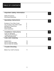
TABLE OF CONTENTS Important Safety Information 3 Safety Precautions 3 Grounding Instructions 4 Operating Instructions 5 Features of Your Wine Cooler 5 The Controls of Your Wine Cooler 6 Setting the Temperature 6 Wine Storage 7 Shelf Instructions 7 Installation Instructions 8 Tools You Will Need 8 Preparing the Enclosure 8 Door Swing Reversal 9 Care and Cleaning 10 Helpfull Hints 10 How to Clean the Inside 10 How to Clean the Outside 10 Trouble Shooting 11 Before Your Call For Service 11 1
TABLE OF CONTENTS Important Safety Information 3 Safety Precautions 3 Grounding Instructions 4 Operating Instructions 5 Features of Your Wine Cooler 5 The Controls of Your Wine Cooler 6 Setting the Temperature 6 Wine Storage 7 Shelf Instructions 7 Installation Instructions 8 Tools You Will Need 8 Preparing the Enclosure 8 Door Swing Reversal 9 Care and Cleaning 10 Helpfull Hints 10 How to Clean the Inside 10 How to Clean the Outside 10 Trouble Shooting 11 Before Your Call For Service 11 1
Product Manual
Page 5
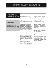
For best operation, plug this appliance into an outlet that is properly installed and grounded. Do not under any circum- stances cut or remove the third (ground) prong from the power cord. In the event of an electrical ... with this appliance. If the power cord is your personal responsibility and obligation to have it is too short, have a qualified electrician or service technician install an outlet near the appliance. 4 Consult a qualified electrician or service technician if the grounding instructions are not completely understood, or if doubt exists as to...
For best operation, plug this appliance into an outlet that is properly installed and grounded. Do not under any circum- stances cut or remove the third (ground) prong from the power cord. In the event of an electrical ... with this appliance. If the power cord is your personal responsibility and obligation to have it is too short, have a qualified electrician or service technician install an outlet near the appliance. 4 Consult a qualified electrician or service technician if the grounding instructions are not completely understood, or if doubt exists as to...
Product Manual
Page 8
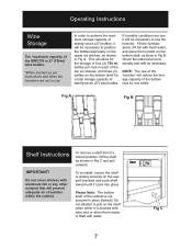
To re-install, ensure the shelf is resting securely on the support brackets and push shelf inward until it will prevent adequate air circulation within the cabinet. Check ...
To re-install, ensure the shelf is resting securely on the support brackets and push shelf inward until it will prevent adequate air circulation within the cabinet. Check ...
Product Manual
Page 9
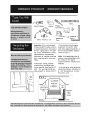
...opening swing. hole *If electrical outlet is in adjacent * cabinetry 2" Electrical Access 6" 12-½" *The listed depth requirment for the installation be on a level floor area and at least 34-1/2". • The electrical outlet may be worn. Important: It is flush mounted ...in the rear wall, not surface mounted in a location that you install the wine cooler in the enclosure. 8 Safety Glasses Gloves Philips Screwdriver Level Flashlight Drill & Hole Saw set Measuring Tape Carpenter's ...
...opening swing. hole *If electrical outlet is in adjacent * cabinetry 2" Electrical Access 6" 12-½" *The listed depth requirment for the installation be on a level floor area and at least 34-1/2". • The electrical outlet may be worn. Important: It is flush mounted ...in the rear wall, not surface mounted in a location that you install the wine cooler in the enclosure. 8 Safety Glasses Gloves Philips Screwdriver Level Flashlight Drill & Hole Saw set Measuring Tape Carpenter's ...
Product Manual
Page 10
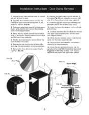
... from the top left side in order to remove the support bracket from the left side of the frame. 10. While the door remains closed install the first screw into the left side bottom hinge. 11. FIG 1D Door Plug FIG 1A Upper Hinge FIG 1C Plastic Caps (3) FIG 1B Lower... 1. Swing the door slightly towards the left side of the frame (the previous hinge location). 9. Remove the three (3) screws supporting the top hinge (Fig 1A). 8. Install the new left hand hinge assembly (supplied with unit) on the left side of the frame (Fig 1C) and reinstall them on the right side...
... from the top left side in order to remove the support bracket from the left side of the frame. 10. While the door remains closed install the first screw into the left side bottom hinge. 11. FIG 1D Door Plug FIG 1A Upper Hinge FIG 1C Plastic Caps (3) FIG 1B Lower... 1. Swing the door slightly towards the left side of the frame (the previous hinge location). 9. Remove the three (3) screws supporting the top hinge (Fig 1A). 8. Install the new left hand hinge assembly (supplied with unit) on the left side of the frame (Fig 1C) and reinstall them on the right side...
