
Owners Manual
Page 3
...card...9 Removing microSD card...9 Installing microSD card...9 Base cover...10 Lithium-ion battery precautions...10 Removing the base cover...10 Installing the base cover...13 Battery...13 Lithium-ion battery precautions...13 Removing the battery...13 Installing the battery...16 Speaker...16 Removing speaker...16 Installing speaker...18 WLAN card...18 Removing ... inside your computer...7 After working inside your computer 5 Safety precautions...5 Electrostatic discharge-ESD protection...5 ESD field service kit ...6 Transporting sensitive components...7 Storing Chromebooks for long term -
...card...9 Removing microSD card...9 Installing microSD card...9 Base cover...10 Lithium-ion battery precautions...10 Removing the base cover...10 Installing the base cover...13 Battery...13 Lithium-ion battery precautions...13 Removing the battery...13 Installing the battery...16 Speaker...16 Removing speaker...16 Installing speaker...18 WLAN card...18 Removing ... inside your computer...7 After working inside your computer 5 Safety precautions...5 Electrostatic discharge-ESD protection...5 ESD field service kit ...6 Transporting sensitive components...7 Storing Chromebooks for long term -
Owners Manual
Page 4
...palmrest...44 Chapter 3: Technology and components 45 Keyboard...45 Keyboard keys function...45 Touchpad...47 Bluetooth...48 Chapter 4: Product specification for Chromebook 5190 49 Chapter 5: Software...51 Operating system...51 Chrome OS...51 Verified Boot...52 Disk Partition Map...53 Developer and Recovery mode...54......58 Power issues...58 CROSH...62 CROSH commands...63 Chrome commands...65 Commonly used CROSH command...70 Check battery charging status...70 Reset Chromebook...77 Recovery Chromebook...80 Recovering the Chromebook...80 Chapter 7: Contacting Dell...83 4 Contents
...palmrest...44 Chapter 3: Technology and components 45 Keyboard...45 Keyboard keys function...45 Touchpad...47 Bluetooth...48 Chapter 4: Product specification for Chromebook 5190 49 Chapter 5: Software...51 Operating system...51 Chrome OS...51 Verified Boot...52 Disk Partition Map...53 Developer and Recovery mode...54......58 Power issues...58 CROSH...62 CROSH commands...63 Chrome commands...65 Commonly used CROSH command...70 Check battery charging status...70 Reset Chromebook...77 Recovery Chromebook...80 Recovering the Chromebook...80 Chapter 7: Contacting Dell...83 4 Contents

Owners Manual
Page 7
...the power button. Update to a charger and a power source, which will not fully run out of the load. 3. Connect the Chromebooks to the latest version of the battery disconnect state. Lift with your legs, not your computer. 3. This ensures that they use anti-static bags for safe transport. The ... multiple Chrome OS versions may have completed the steps and can take time, as replacement parts or parts to be returned to Dell, it will get them to long term (Summer) storage: 1. Connect the device to prevent the computer cover from all times when servicing...
...the power button. Update to a charger and a power source, which will not fully run out of the load. 3. Connect the Chromebooks to the latest version of the battery disconnect state. Lift with your legs, not your computer. 3. This ensures that they use anti-static bags for safe transport. The ... multiple Chrome OS versions may have completed the steps and can take time, as replacement parts or parts to be returned to Dell, it will get them to long term (Summer) storage: 1. Connect the device to prevent the computer cover from all times when servicing...

Owners Manual
Page 8
...the back of the computer. 8. CAUTION: To guard against electrical shock unplug your computer. After working inside your computer. Replace the battery. 2. Connect any external devices, such as a port replicator or media base, and replace any installed ExpressCards or Smart Cards from... the electrical outlet before turning on your computer About this particular Dell computer. Connect any external devices, cards, and cables before performing Step # 8. CAUTION: To avoid damage to the computer, use batteries designed for few seconds, to ground the system board. Replace ...
...the back of the computer. 8. CAUTION: To guard against electrical shock unplug your computer. After working inside your computer. Replace the battery. 2. Connect any external devices, such as a port replicator or media base, and replace any installed ExpressCards or Smart Cards from... the electrical outlet before turning on your computer About this particular Dell computer. Connect any external devices, cards, and cables before performing Step # 8. CAUTION: To avoid damage to the computer, use batteries designed for few seconds, to ground the system board. Replace ...

Owners Manual
Page 9
2 Removing and installing components Topics: • microSD card • Base cover • Battery • Speaker • WLAN card • Input Output board • Touchpad • Keyboard • System board • Display assembly • Display bezel • Display panel &#...
2 Removing and installing components Topics: • microSD card • Base cover • Battery • Speaker • WLAN card • Input Output board • Touchpad • Keyboard • System board • Display assembly • Display bezel • Display panel &#...

Owners Manual
Page 10
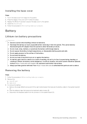
Removing the base cover Steps 1. Remove the microSD card. 3. Contact https://www.dell.com/support for assistance and further instructions. ● Always purchase genuine batteries from https://www.dell.com or authorized Dell partners and re-sellers. Remove the 9 (M2.5x7.5) screws that secure ...To remove the base cover: a. Base cover Lithium-ion battery precautions CAUTION: ● Exercise caution when handling Lithium-ion batteries. ● Discharge the battery as much as puncturing, bending, or crushing a Lithium-ion battery can be done by disconnecting the AC adapter from the...
Removing the base cover Steps 1. Remove the microSD card. 3. Contact https://www.dell.com/support for assistance and further instructions. ● Always purchase genuine batteries from https://www.dell.com or authorized Dell partners and re-sellers. Remove the 9 (M2.5x7.5) screws that secure ...To remove the base cover: a. Base cover Lithium-ion battery precautions CAUTION: ● Exercise caution when handling Lithium-ion batteries. ● Discharge the battery as much as puncturing, bending, or crushing a Lithium-ion battery can be done by disconnecting the AC adapter from the...
Owners Manual
Page 13
...● Do not apply pressure to the surface of the battery. ● Do not bend the battery. ● Do not use tools of any kind to free it from https://www.dell.com or authorized Dell partners and re-sellers. In such an instance, the entire...into place. 3. c. Toe in After working inside your computer. 2. Removing the battery Steps 1. To remove the battery: a. Contact https://www.dell.com/support for assistance and further instructions. ● Always purchase genuine batteries from the system. Removing and installing components 13 base cover 3. b. Peel the ...
...● Do not apply pressure to the surface of the battery. ● Do not bend the battery. ● Do not use tools of any kind to free it from https://www.dell.com or authorized Dell partners and re-sellers. In such an instance, the entire...into place. 3. c. Toe in After working inside your computer. 2. Removing the battery Steps 1. To remove the battery: a. Contact https://www.dell.com/support for assistance and further instructions. ● Always purchase genuine batteries from the system. Removing and installing components 13 base cover 3. b. Peel the ...
Owners Manual
Page 14
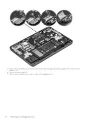
Unroute the battery cable [3]. Remove the single (M2x3) screw and lift the left metal bracket that secures the battery cable to the connector on the battery [1, 2]. f. Peel the adhesive that secures the battery cable to the system board [4]. 14 Removing and installing components d. e.
Unroute the battery cable [3]. Remove the single (M2x3) screw and lift the left metal bracket that secures the battery cable to the connector on the battery [1, 2]. f. Peel the adhesive that secures the battery cable to the system board [4]. 14 Removing and installing components d. e.
Owners Manual
Page 15
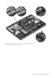
Lift the battery away from the system [2]. g. Removing and installing components 15 h. Remove the 3 (M2x3) screws that secure the battery to the system [1].
Lift the battery away from the system [2]. g. Removing and installing components 15 h. Remove the 3 (M2x3) screws that secure the battery to the system [1].

Owners Manual
Page 16
...the connector on the system board. 4. Follow the procedure in After working inside your computer. 2. Place the 2 metal brackets to secure the battery cable to its connector on each metal bracket, to secure each bracket to the system. 3. Replace the 2 (M2x3) screws, one on ...the system board and the battery. 6. microSD card 8. To remove the speaker: a. Installing the battery Steps 1. Route the battery cable and connect the cable to the system board. 5. Remove the: a. Install the: a. Follow the procedure...
...the connector on the system board. 4. Follow the procedure in After working inside your computer. 2. Place the 2 metal brackets to secure the battery cable to its connector on each metal bracket, to secure each bracket to the system. 3. Replace the 2 (M2x3) screws, one on ...the system board and the battery. 6. microSD card 8. To remove the speaker: a. Installing the battery Steps 1. Route the battery cable and connect the cable to the system board. 5. Remove the: a. Install the: a. Follow the procedure...

Owners Manual
Page 18
... that secures the WLAN antenna cables [2]. Connect the speaker cable to the connector on the WLAN card [3]. battery b. microSD card b. Remove the WLAN card bracket that secures the WLAN card bracket to the system. 4. battery 3. Installing speaker Steps 1. WLAN card Removing WLAN card Steps 1. d. Slide and lift the WLAN card away from...
... that secures the WLAN antenna cables [2]. Connect the speaker cable to the connector on the WLAN card [3]. battery b. microSD card b. Remove the WLAN card bracket that secures the WLAN card bracket to the system. 4. battery 3. Installing speaker Steps 1. WLAN card Removing WLAN card Steps 1. d. Slide and lift the WLAN card away from...

Owners Manual
Page 19
Insert the WLAN card into the slot on the WLAN card. 3. battery b. Follow the procedure in After working inside your computer. Removing and installing components 19 Replace the single (M2x3) screw to secure the WLAN card bracket to the connectors on the system. 2. base cover c. microSD card 6. Connect the WLAN antenna cables to the system. 5. Install the: a. Place the WLAN card bracket to secure the WLAN cables to the WLAN card. 4. Installing WLAN card Steps 1.
Insert the WLAN card into the slot on the WLAN card. 3. battery b. Follow the procedure in After working inside your computer. Removing and installing components 19 Replace the single (M2x3) screw to secure the WLAN card bracket to the connectors on the system. 2. base cover c. microSD card 6. Connect the WLAN antenna cables to the system. 5. Install the: a. Place the WLAN card bracket to secure the WLAN cables to the WLAN card. 4. Installing WLAN card Steps 1.

Owners Manual
Page 20
... [3]. base cover c. d. e. microSD card b. Remove the 2 (M2x4) screws that secure the I /O board away from the system. Follow the procedure in Before working inside your computer. 2. battery 3. b. f. Remove the: a. Lift the I /O board to the system [2]. Lift the latch and, disconnect the two I/O cables from the slot on the I /O board): a. Lift the bracket...
... [3]. base cover c. d. e. microSD card b. Remove the 2 (M2x4) screws that secure the I /O board away from the system. Follow the procedure in Before working inside your computer. 2. battery 3. b. f. Remove the: a. Lift the I /O board to the system [2]. Lift the latch and, disconnect the two I/O cables from the slot on the I /O board): a. Lift the bracket...

Owners Manual
Page 21
Place the I /O board. 4. Connect the two I/O cables and close the latch to secure it to the I /O bracket and replace the 2 (M2x4) screws to secure the bracket to the system. 5. Removing and installing components 21 battery b. microSD card 6. base cover c. Replace the 2 (M2x3) screws to secure the I /O) board to the system board. 3. Place the Input output (I /O board to its slot in After working inside your computer. Follow the procedure in the system. 2. Install the: a. Installing Input output board Steps 1.
Place the I /O board. 4. Connect the two I/O cables and close the latch to secure it to the I /O bracket and replace the 2 (M2x4) screws to secure the bracket to the system. 5. Removing and installing components 21 battery b. microSD card 6. base cover c. Replace the 2 (M2x3) screws to secure the I /O) board to the system board. 3. Place the Input output (I /O board to its slot in After working inside your computer. Follow the procedure in the system. 2. Install the: a. Installing Input output board Steps 1.

Owners Manual
Page 22
Follow the procedure in the touchpad frame [1]. Lift the latch and, disconnect the touchpad cable from the connector in Before working inside your computer. 2. base cover c. b. d. c. Remove the 3 (M2x3) screws that secures the touchpad frame to the system [1]. Remove the: a. Remove the touchpad bracket [2]. microSD card b. Peel the adhesive tape that secure the touchpad bracket to the system [2]. 22 Removing and installing components Touchpad Removing the touchpad Steps 1. To remove the touchpad: a. battery 3.
Follow the procedure in the touchpad frame [1]. Lift the latch and, disconnect the touchpad cable from the connector in Before working inside your computer. 2. base cover c. b. d. c. Remove the 3 (M2x3) screws that secures the touchpad frame to the system [1]. Remove the: a. Remove the touchpad bracket [2]. microSD card b. Peel the adhesive tape that secure the touchpad bracket to the system [2]. 22 Removing and installing components Touchpad Removing the touchpad Steps 1. To remove the touchpad: a. battery 3.

Owners Manual
Page 24
... scribe to the connector in the system [2]. Place the touchpad bracket into the slot. 6. Replace the 3 screws to secure the touchpad bracket to the system. 3. battery b. Keyboard Removing keyboard Steps 1. base cover c. Replace the 3 screws to secure the touchpad frame to the system. 7. base cover c. Follow the procedure in Before working...
... scribe to the connector in the system [2]. Place the touchpad bracket into the slot. 6. Replace the 3 screws to secure the touchpad bracket to the system. 3. battery b. Keyboard Removing keyboard Steps 1. base cover c. Replace the 3 screws to secure the touchpad frame to the system. 7. base cover c. Follow the procedure in Before working...
Owners Manual
Page 26
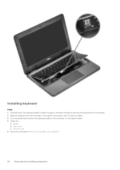
Installing keyboard Steps 1. microSD card 5. Turn the system and connect the keyboard cable to the connector on the palm rest before securing the keyboard onto the system. 2. battery b. Carefully insert the keyboard cable through the gap on the system board. 4. base cover c. Follow the procedure in After working inside your computer. 26 Removing and installing components Align the keyboard trim with the tabs on the system, and press it until it clicks into place. 3. Install the: a.
Installing keyboard Steps 1. microSD card 5. Turn the system and connect the keyboard cable to the connector on the palm rest before securing the keyboard onto the system. 2. battery b. Carefully insert the keyboard cable through the gap on the system board. 4. base cover c. Follow the procedure in After working inside your computer. 26 Removing and installing components Align the keyboard trim with the tabs on the system, and press it until it clicks into place. 3. Install the: a.
Owners Manual
Page 27
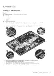
base cover c. To remove the system board: a. c. f. microSD card b. battery d. Remove the single (M2x4) screw that secures the eDP bracket to the system [5]. Lift the latch and, disconnect the eDP cable from the connector on ...
base cover c. To remove the system board: a. c. f. microSD card b. battery d. Remove the single (M2x4) screw that secures the eDP bracket to the system [5]. Lift the latch and, disconnect the eDP cable from the connector on ...

Owners Manual
Page 30
...replace the single screw to secure the bracket to the system board. 8. WLAN b. base cover d. Display assembly Removing display assembly Steps 1. battery 3. b. Remove the eDP bracket away from the connector on the bracket to the retention tab in Before working inside your computer. Peel the... the procedure in the system. 4. d. Connect the 2 Input/Output cable, touchpad cable and keyboard cable to the connectors on the system. 2. battery c. Peel the adhesive tape that secures the eDP cable to the system. 3. Align the system board bracket and snap the hook on the system ...
...replace the single screw to secure the bracket to the system board. 8. WLAN b. base cover d. Display assembly Removing display assembly Steps 1. battery 3. b. Remove the eDP bracket away from the connector on the bracket to the retention tab in Before working inside your computer. Peel the... the procedure in the system. 4. d. Connect the 2 Input/Output cable, touchpad cable and keyboard cable to the connectors on the system. 2. battery c. Peel the adhesive tape that secures the eDP cable to the system. 3. Align the system board bracket and snap the hook on the system ...

Owners Manual
Page 32
Place the chassis on the system board. 6. Install the: a. battery b. i. Installing display assembly Steps 1. Lift the system and close the display. 5. microSD card 10. Remove the 6 (M2.5x5) display hinge bracket screws that secure the ...
Place the chassis on the system board. 6. Install the: a. battery b. i. Installing display assembly Steps 1. Lift the system and close the display. 5. microSD card 10. Remove the 6 (M2.5x5) display hinge bracket screws that secure the ...


