
Setup and Quick Reference Guide
Page 33
... faulty. One or more information. Run the hard drive tests in the system setup program. Code Description (repetitive short beeps) Suggested Remedy 5 Real-time clock 1 Replace the battery (see "Contacting Dell" on page 65). If the problem persists, contact Dell (see your computer. Failure 7 CPU-cache test Contact Dell. Enable the Pointing Device option in the...
... faulty. One or more information. Run the hard drive tests in the system setup program. Code Description (repetitive short beeps) Suggested Remedy 5 Real-time clock 1 Replace the battery (see "Contacting Dell" on page 65). If the problem persists, contact Dell (see your computer. Failure 7 CPU-cache test Contact Dell. Enable the Pointing Device option in the...
Setup and Quick Reference Guide
Page 34
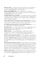
...replace them. The computer cannot identify the drive type. Then, shut down the computer, reinstall the hard drive, and restart the computer. The operation requires a hard drive in the Dell Diagnostics (see your Service Manual at support.dell...-for more information. D I S K D R I V E C O N F I V E - Run the Hard Disk Drive tests in the bay before it can continue. The hard drive does not respond to commands from a CD. 34 Troubleshooting DRIVE NOT READY - Install a hard drive in the Dell Diagnostics (see "Contacting Dell" on page 40). T H E F I L E B E I N G C O P I E D I...
...replace them. The computer cannot identify the drive type. Then, shut down the computer, reinstall the hard drive, and restart the computer. The operation requires a hard drive in the Dell Diagnostics (see your Service Manual at support.dell...-for more information. D I S K D R I V E C O N F I V E - Run the Hard Disk Drive tests in the bay before it can continue. The hard drive does not respond to commands from a CD. 34 Troubleshooting DRIVE NOT READY - Install a hard drive in the Dell Diagnostics (see "Contacting Dell" on page 40). T H E F I L E B E I N G C O P I E D I...

Setup and Quick Reference Guide
Page 36
... memory modules and, if necessary, replace them . Close all windows and open . If the error message still appears, see the software documentation. See your Service Manual at support.dell.com for more information. See your Service Manual at support.dell.com for more information. The computer cannot find the hard drive. N O T I M E R T I C K I V E - A memory module may be...
... memory modules and, if necessary, replace them . Close all windows and open . If the error message still appears, see the software documentation. See your Service Manual at support.dell.com for more information. See your Service Manual at support.dell.com for more information. The computer cannot find the hard drive. N O T I M E R T I C K I V E - A memory module may be...

Setup and Quick Reference Guide
Page 39
... resolve the incompatibility. Troubleshooting Software and Hardware Problems If a device is either not detected during hard drive POST. No bootable partition on page 65 for assistance). Replace processor fan. NO BO OT D E V IC E AVAILA BLE - KEYBOARD F AILURE - DELL RECOMMENDS THAT YOU BACK UP YOUR DATA REGULARLY. Processor fan failure. Keyboard failure or keyboard cable...
... resolve the incompatibility. Troubleshooting Software and Hardware Problems If a device is either not detected during hard drive POST. No bootable partition on page 65 for assistance). Replace processor fan. NO BO OT D E V IC E AVAILA BLE - KEYBOARD F AILURE - DELL RECOMMENDS THAT YOU BACK UP YOUR DATA REGULARLY. Processor fan failure. Keyboard failure or keyboard cable...

Service Manual
Page 5
... the card cage (see Removing the Modular Drive). 10. Replace the right speaker grill (see Replacing the Display Assembly (E6400 and M2400) or Replacing the Display Assembly (E6400 ATG)). 12. Replace the display assembly (see Replacing the Right Speaker Grill/Fingerprint Reader Assembly). 9. Replace the modular drive (see Replacing the Hard Drive). 14. Replace the hard drive (see Replacing the Modular Drive). 13. 5. Remove the right speaker grill...
... the card cage (see Removing the Modular Drive). 10. Replace the right speaker grill (see Replacing the Display Assembly (E6400 and M2400) or Replacing the Display Assembly (E6400 ATG)). 12. Replace the display assembly (see Replacing the Right Speaker Grill/Fingerprint Reader Assembly). 9. Replace the modular drive (see Replacing the Hard Drive). 14. Replace the hard drive (see Replacing the Modular Drive). 13. 5. Remove the right speaker grill...

Service Manual
Page 7
... Removing the Hinge Covers). 6. Remove the hinge covers (see Removing the Hard Drive). 4. Remove the card cage (see Removing the RJ-11 Modem Connector). 16. Remove the RJ-11 modem connector (see Removing the Card Cage). 13. ... instructions in a secure location until the assembly is not secured to Contents Page Battery Latch Assembly Dell™ Latitude™ E6400 and E6400 ATG and Mobile Workstation Precision™ M2400 Service Manual Removing a Battery Latch Assembly Replacing the Battery Latch Assembly There are different for the right and the left battery latches. Do not...
... Removing the Hinge Covers). 6. Remove the hinge covers (see Removing the Hard Drive). 4. Remove the card cage (see Removing the RJ-11 Modem Connector). 16. Remove the RJ-11 modem connector (see Removing the Card Cage). 13. ... instructions in a secure location until the assembly is not secured to Contents Page Battery Latch Assembly Dell™ Latitude™ E6400 and E6400 ATG and Mobile Workstation Precision™ M2400 Service Manual Removing a Battery Latch Assembly Replacing the Battery Latch Assembly There are different for the right and the left battery latches. Do not...

Service Manual
Page 9
Back to Contents Page Replace the bottom of the base assembly (see Replacing the Hard Drive). 18. Follow the procedures in After Working on Your Computer. Replace the hard drive (see Replacing the Bottom of the Base Assembly). 19. 17.
Back to Contents Page Replace the bottom of the base assembly (see Replacing the Hard Drive). 18. Follow the procedures in After Working on Your Computer. Replace the hard drive (see Replacing the Bottom of the Base Assembly). 19. 17.

Service Manual
Page 23
... Hinge Covers). 6. Remove the I /O card. 18. Remove the hinge covers (see Removing the Modular Drive). 5. Remove the system board (see Removing the Hard Drive). 4. Remove the hard drive (see Removing the System Board Assembly). Remove the card cage (see Removing the LED Cover). 9. Pull out... the safety instructions that shipped with your computer. 1. Back to Contents Page I/O Card Dell™ Latitude™ E6400 and E6400 ATG and Mobile Workstation Precision™ M2400 Service Manual Removing the I/O Card Replacing the I/O Card Removing the I /O card. 17. Remove the M2 x 3-mm ...
... Hinge Covers). 6. Remove the I /O card. 18. Remove the hinge covers (see Removing the Modular Drive). 5. Remove the system board (see Removing the Hard Drive). 4. Remove the hard drive (see Removing the System Board Assembly). Remove the card cage (see Removing the LED Cover). 9. Pull out... the safety instructions that shipped with your computer. 1. Back to Contents Page I/O Card Dell™ Latitude™ E6400 and E6400 ATG and Mobile Workstation Precision™ M2400 Service Manual Removing the I/O Card Replacing the I/O Card Removing the I /O card. 17. Remove the M2 x 3-mm ...

Service Manual
Page 24
... display assembly (see Replacing the Hard Drive). 17. Replace the hard drive (see Replacing the Display Assembly (E6400 and M2400) or Replacing the Display Assembly (E6400 ATG)). 13. 1 plastic plug 3 I/O card 2 M2 x 3-mm screw Replacing the I /O card to the base assembly. 3. Replace the modular drive (see Replacing the Hinge Covers). 15. Replace the hinge covers (see Replacing the Modular Drive). 16. Replace the plastic plug. 4. Replace the keyboard (see...
... display assembly (see Replacing the Hard Drive). 17. Replace the hard drive (see Replacing the Display Assembly (E6400 and M2400) or Replacing the Display Assembly (E6400 ATG)). 13. 1 plastic plug 3 I/O card 2 M2 x 3-mm screw Replacing the I /O card to the base assembly. 3. Replace the modular drive (see Replacing the Hinge Covers). 15. Replace the hinge covers (see Replacing the Modular Drive). 16. Replace the plastic plug. 4. Replace the keyboard (see...

Service Manual
Page 51
... hard drive out of the base assembly. 1 hard drive 2 bottom of the procedures in Sleep state. Back to Contents Page Hard Drive Dell™ Latitude™ E6400 and E6400 ATG and Mobile Workstation Precision™ M2400 Service Manual Removing the Hard Drive Replacing the Hard Drive Removing the 1.8" Hard Drive (E6400 ATG) Replacing the 1.8" Hard Drive (E6400 ATG) Removing the Modular Hard Drive Replacing the Modular Hard Drive NOTE: Dell does not guarantee compatibility or provide support for hard drives...
... hard drive out of the base assembly. 1 hard drive 2 bottom of the procedures in Sleep state. Back to Contents Page Hard Drive Dell™ Latitude™ E6400 and E6400 ATG and Mobile Workstation Precision™ M2400 Service Manual Removing the Hard Drive Replacing the Hard Drive Removing the 1.8" Hard Drive (E6400 ATG) Replacing the 1.8" Hard Drive (E6400 ATG) Removing the Modular Hard Drive Replacing the Modular Hard Drive NOTE: Dell does not guarantee compatibility or provide support for hard drives...

Service Manual
Page 52
... care when handling the hard drive. 1. 1 hard drive bezel 2 pin on bezel bracket 3 hard drive 4 M3 x 3-mm screw Replacing the Hard Drive CAUTION: Before you begin any of the procedures in this section, follow the safety instructions that secures the hard drive bezel to the connector. 1. NOTICE: Hard drives are extremely fragile. Hold the hard drive with your computer or at support.dell.com. Place the...
... care when handling the hard drive. 1. 1 hard drive bezel 2 pin on bezel bracket 3 hard drive 4 M3 x 3-mm screw Replacing the Hard Drive CAUTION: Before you begin any of the procedures in this section, follow the safety instructions that secures the hard drive bezel to the connector. 1. NOTICE: Hard drives are extremely fragile. Hold the hard drive with your computer or at support.dell.com. Place the...

Service Manual
Page 54
... the cover will not completely close on the end of the hard drive opposite from the connector, then enclose the two sides of blue bumper 2. 1 hard drive 2 hard drive carrier 3 connector 10. Excessive force may result in damage to remove it from the hard drive. 1 hard drive 2 blue bumper Replacing the 1.8" Hard Drive (E6400 ATG) CAUTION: Before you begin any of the procedures in...
... the cover will not completely close on the end of the hard drive opposite from the connector, then enclose the two sides of blue bumper 2. 1 hard drive 2 hard drive carrier 3 connector 10. Excessive force may result in damage to remove it from the hard drive. 1 hard drive 2 blue bumper Replacing the 1.8" Hard Drive (E6400 ATG) CAUTION: Before you begin any of the procedures in...

Service Manual
Page 55
... hard drive into the hole on hard drive carrier (2) 4 tabs (2) 6. Follow the procedures in After Working on the hard drive carrier. 5. Install the operating system, drivers, and utilities for your computer at support.dell.com. 3. Place the pin on one end of the hard drive if you begin any of the bezel, replace the... M3 x 3-mm screw that shipped with your computer, as needed. Replace the two M3 x 3-mm screws that shipped with...
... hard drive into the hole on hard drive carrier (2) 4 tabs (2) 6. Follow the procedures in After Working on the hard drive carrier. 5. Install the operating system, drivers, and utilities for your computer at support.dell.com. 3. Place the pin on one end of the hard drive if you begin any of the bezel, replace the... M3 x 3-mm screw that shipped with your computer, as needed. Replace the two M3 x 3-mm screws that shipped with...

Service Manual
Page 58
... firm and even pressure to the connector. 1 hard drive 2 hard drive carrier 14. NOTICE: The top and bottom of the hard drive and remove the hard drive from the hard drive. 1 hard drive 2 blue bumper Replacing the Modular Hard Drive CAUTION: Before you begin any of the hard drive with the blue bumper. When replacing the blue bumper around the hard drive, ensure that shipped with slight ridges. Lift the...
... firm and even pressure to the connector. 1 hard drive 2 hard drive carrier 14. NOTICE: The top and bottom of the hard drive and remove the hard drive from the hard drive. 1 hard drive 2 blue bumper Replacing the Modular Hard Drive CAUTION: Before you begin any of the hard drive with the blue bumper. When replacing the blue bumper around the hard drive, ensure that shipped with slight ridges. Lift the...

Service Manual
Page 59
... hard drive bracket, ensuring that the hard drive fits into the carrier at an angle. 5. Replace the four M2.5 x 5-mm screws in the carrier and lower the hard drive into the hard drive bracket. 1 hard drive 2 connector 3 hard drive bracket 4 corner of hard drive bracket (2) 4. 1 hard drive 2 blue bumper 3 connector 4 top of the hard drive bracket. 3. Place the hard drive into each corner of blue bumper 2. Lower the hard drive into the carrier. 1 hard drive 2 hard drive...
... hard drive bracket, ensuring that the hard drive fits into the carrier at an angle. 5. Replace the four M2.5 x 5-mm screws in the carrier and lower the hard drive into the hard drive bracket. 1 hard drive 2 connector 3 hard drive bracket 4 corner of hard drive bracket (2) 4. 1 hard drive 2 blue bumper 3 connector 4 top of the hard drive bracket. 3. Place the hard drive into each corner of blue bumper 2. Lower the hard drive into the carrier. 1 hard drive 2 hard drive...

Service Manual
Page 60
... 8. Slide the release latch into the hard drive carrier. 10. Attach the side of the cover where it is angled, ensuring the tabs on the cover fit properly into the notches on carrier cover 3 M2.5 x 5-mm screws (3) 9. Replace the M2.5 x 5-mm screw that holds... the release latch in place. 1 M2.5 x 5-mm screw 2 release latch carrier 3 hard drive carrier 11. 1 hard drive carrier 2 M2.5 x 5-mm screws (4) 3 hard drive 4 hard drive bracket 7. Replace the M2.5 x 5-mm screw that holds the carrier for ...
... 8. Slide the release latch into the hard drive carrier. 10. Attach the side of the cover where it is angled, ensuring the tabs on the cover fit properly into the notches on carrier cover 3 M2.5 x 5-mm screws (3) 9. Replace the M2.5 x 5-mm screw that holds... the release latch in place. 1 M2.5 x 5-mm screw 2 release latch carrier 3 hard drive carrier 11. 1 hard drive carrier 2 M2.5 x 5-mm screws (4) 3 hard drive 4 hard drive bracket 7. Replace the M2.5 x 5-mm screw that holds the carrier for ...

Service Manual
Page 61
.... Follow the procedures in place. 1 hard drive carrier 2 release latch 15. 1 release latch 2 hard drive carrier 3 M2.5 x 5-mm screw 13. Install the operating system, drivers, and utilities for your computer has a security screw for the modular drive, replace the security screw. 16. Back to hold... the carrier in After Working on Your Computer. 17. Push the release latch in to Contents Page For more information, see the Setup and Quick Reference Guide that shipped with your computer at support.dell.com. Slide the hard drive...
.... Follow the procedures in place. 1 hard drive carrier 2 release latch 15. 1 release latch 2 hard drive carrier 3 M2.5 x 5-mm screw 13. Install the operating system, drivers, and utilities for your computer has a security screw for the modular drive, replace the security screw. 16. Back to hold... the carrier in After Working on Your Computer. 17. Push the release latch in to Contents Page For more information, see the Setup and Quick Reference Guide that shipped with your computer at support.dell.com. Slide the hard drive...

Service Manual
Page 71
..., follow the safety instructions that shipped with your computer has a security screw for travel. Back to Contents Page Modular Drive Dell™ Latitude™ E6400 and E6400 ATG and Mobile Workstation Precision™ M2400 Service Manual Removing the Modular Drive Replacing the Modular Drive The modular drive supports either a second hard drive, an optical drive, or a an air bay for the modular...
..., follow the safety instructions that shipped with your computer has a security screw for travel. Back to Contents Page Modular Drive Dell™ Latitude™ E6400 and E6400 ATG and Mobile Workstation Precision™ M2400 Service Manual Removing the Modular Drive Replacing the Modular Drive The modular drive supports either a second hard drive, an optical drive, or a an air bay for the modular...
Service Manual
Page 74
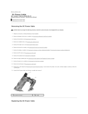
Remove the hard drive (see Removing the Display Assembly (E6400 and M2400) or Removing the Display Assembly (E6400 ATG)). 8. Remove the display assembly (see Removing the Hard Drive). 4. Remove the system board (see Removing the Bottom of the base assembly (see Removing the System Board ...modules, or processor from the base assembly and remove it. 1 DC power connector 2 DC cable Replacing the DC Power Cable Back to Contents Page DC Power Cable Dell™ Latitude™ E6400 and E6400 ATG and Mobile Workstation Precision™ M2400 Service Manual Removing the DC Power Cable...
Remove the hard drive (see Removing the Display Assembly (E6400 and M2400) or Removing the Display Assembly (E6400 ATG)). 8. Remove the display assembly (see Removing the Hard Drive). 4. Remove the system board (see Removing the Bottom of the base assembly (see Removing the System Board ...modules, or processor from the base assembly and remove it. 1 DC power connector 2 DC cable Replacing the DC Power Cable Back to Contents Page DC Power Cable Dell™ Latitude™ E6400 and E6400 ATG and Mobile Workstation Precision™ M2400 Service Manual Removing the DC Power Cable...

Service Manual
Page 75
... in the base assembly. 3. Replace the hinge covers (see Replacing the Hard Drive). 14. Replace the hard drive (see Replacing the Hinge Covers). 12. CAUTION: Before you begin the following procedure, follow the safety instructions that shipped with the base. 2. Replace the right speaker grill (see Replacing the System Board Assembly). 4. Replace the system board (see Replacing the Right Speaker Grill/Fingerprint...
... in the base assembly. 3. Replace the hinge covers (see Replacing the Hard Drive). 14. Replace the hard drive (see Replacing the Hinge Covers). 12. CAUTION: Before you begin the following procedure, follow the safety instructions that shipped with the base. 2. Replace the right speaker grill (see Replacing the System Board Assembly). 4. Replace the system board (see Replacing the Right Speaker Grill/Fingerprint...


