
Dell™ Technology Guide
Page 54
... enable or disable the ambient light sensor feature by pressing the and left-arrow key combination. If covered, the sensor-when enabled-automatically sets the display brightness to the minimum level. NOTE: Do not cover the ambient light sensor with any adhesive labels. Using the display brightness key combinations disables the ambient...
... enable or disable the ambient light sensor feature by pressing the and left-arrow key combination. If covered, the sensor-when enabled-automatically sets the display brightness to the minimum level. NOTE: Do not cover the ambient light sensor with any adhesive labels. Using the display brightness key combinations disables the ambient...

Dell™ Technology Guide
Page 150
... INFORMATION: To learn more computers with each computer. This type of networked computers. See "Managing Networked Computers With Intel® Active Management Technology" on some Dell computers. Local Area Networks (LAN) 1 2 3 4 1 Cable 3 Modem 2 Router 4 Internet A local area network (LAN) connects two or more about networks, see Windows Help and Support: click... or → Help and Support. The Intel® Active Management Technology (Intel AMT or iAMT®) provides enhanced tools for management of computer network generally covers a small area.
... INFORMATION: To learn more computers with each computer. This type of networked computers. See "Managing Networked Computers With Intel® Active Management Technology" on some Dell computers. Local Area Networks (LAN) 1 2 3 4 1 Cable 3 Modem 2 Router 4 Internet A local area network (LAN) connects two or more about networks, see Windows Help and Support: click... or → Help and Support. The Intel® Active Management Technology (Intel AMT or iAMT®) provides enhanced tools for management of computer network generally covers a small area.

Dell™ Technology Guide
Page 159
... network, also known as the computer is a high-speed digital cellular network that provides Internet access over a much wider geographical area than a WLAN, which typically covers only from 100 to make a call from your cellular phone in a specific geographical location, that location may have come on the media that may have...
... network, also known as the computer is a high-speed digital cellular network that provides Internet access over a much wider geographical area than a WLAN, which typically covers only from 100 to make a call from your cellular phone in a specific geographical location, that location may have come on the media that may have...

Dell™ Technology Guide
Page 346
... equals 1024 KB. A bay that provides a fast throughput for a parallel connection to as optical drives, a second battery, or a Dell TravelLite™ module. A temporary data storage area inside your computer. Because the data in 346 A LAN can be connected to another... bits per second - media bay - key combination - A command requiring you to the processor. kilohertz - L LAN - megabytes per second. A computer network covering a small area. light-emitting diode - M Mb - When used for networks and modems. MB - A LAN usually is often referred to a printer or ...
... equals 1024 KB. A bay that provides a fast throughput for a parallel connection to as optical drives, a second battery, or a Dell TravelLite™ module. A temporary data storage area inside your computer. Because the data in 346 A LAN can be connected to another... bits per second - media bay - key combination - A command requiring you to the processor. kilohertz - L LAN - megabytes per second. A computer network covering a small area. light-emitting diode - M Mb - When used for networks and modems. MB - A LAN usually is often referred to a printer or ...

Dell™ Technology Guide
Page 353
... be defined as x horizontal pixels by y vertical pixels by y rows of colors that communicate with each other over the air waves using cellular technology and covering a much larger geographic area than system memory. Character-based software, such as text editors, displays in your wallpaper through the Windows Control Panel. A virus program...
... be defined as x horizontal pixels by y vertical pixels by y rows of colors that communicate with each other over the air waves using cellular technology and covering a much larger geographic area than system memory. Character-based software, such as text editors, displays in your wallpaper through the Windows Control Panel. A virus program...

Setup Guide
Page 43
...series of beeps, called a beep code, identifies a problem. Write down the beep code and contact Dell (see "Using Support Tools" on page 48 or "Contacting Dell" on page 72). Chipset error Four RAM read/write failure Five Real Time Clock failure Six Video... the memory module, ensure that the memory module is seated properly. WARNING: Only trained service personnel should remove the computer cover. INSPIRON Solving Problems This section provides troubleshooting information for advanced service instructions. Three Possible system board failure - BIOS ROM checksum failure...
...series of beeps, called a beep code, identifies a problem. Write down the beep code and contact Dell (see "Using Support Tools" on page 48 or "Contacting Dell" on page 72). Chipset error Four RAM read/write failure Five Real Time Clock failure Six Video... the memory module, ensure that the memory module is seated properly. WARNING: Only trained service personnel should remove the computer cover. INSPIRON Solving Problems This section provides troubleshooting information for advanced service instructions. Three Possible system board failure - BIOS ROM checksum failure...
Service Manual
Page 1
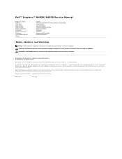
..., Inc. Bluetooth is strictly forbidden. A00 Trademarks used in the United States and/or other than its own. Dell™ Inspiron™ N4020/N4030 Service Manual Before You Begin Battery Hard Drive Optical Drive Module Cover Memory Module(s) Keyboard Wireless Mini-Card Palm Rest Power Button Board Display Camera Internal Card With Bluetooth®...
..., Inc. Bluetooth is strictly forbidden. A00 Trademarks used in the United States and/or other than its own. Dell™ Inspiron™ N4020/N4030 Service Manual Before You Begin Battery Hard Drive Optical Drive Module Cover Memory Module(s) Keyboard Wireless Mini-Card Palm Rest Power Button Board Display Camera Internal Card With Bluetooth®...
Service Manual
Page 2
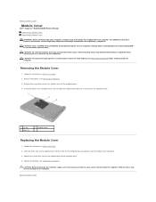
... computer base. 4. Back to Contents Page Module Cover Dell™ Inspiron™ N4020/N4030 Service Manual Removing the Module Cover Replacing the Module Cover WARNING: Before working inside the computer. Damage due to the computer base. 4. Remove the screw that secures the module cover to servicing that secures the module cover to the computer. Slide the three tabs...
... computer base. 4. Back to Contents Page Module Cover Dell™ Inspiron™ N4020/N4030 Service Manual Removing the Module Cover Replacing the Module Cover WARNING: Before working inside the computer. Damage due to the computer base. 4. Remove the screw that secures the module cover to servicing that secures the module cover to the computer. Slide the three tabs...
Service Manual
Page 3
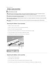
... Latch Assembly 1. Follow the instructions in Before You Begin. 2. Back to Contents Page Battery Latch Assembly Dell™ Inspiron™ N4020/N4030 Service Manual Removing the Battery Latch Assembly Replacing the Battery Latch Assembly WARNING: Before working inside your computer,... read the safety information that is not authorized by Dell™ is not covered by periodically touching an unpainted metal surface (such...
... Latch Assembly 1. Follow the instructions in Before You Begin. 2. Back to Contents Page Battery Latch Assembly Dell™ Inspiron™ N4020/N4030 Service Manual Removing the Battery Latch Assembly Replacing the Battery Latch Assembly WARNING: Before working inside your computer,... read the safety information that is not authorized by Dell™ is not covered by periodically touching an unpainted metal surface (such...
Service Manual
Page 5
...have read the safety information that the computer is not covered by your own personal safety. Save and close all...: l Small flat-blade screwdriver l Phillips screwdriver l Plastic scribe l BIOS executable update program available at www.dell.com/regulatory_compliance. CAUTION: Handle components and cards with your computer. l A component can be replaced or-if ... pull connectors apart, keep them evenly aligned to Contents Page Before You Begin Dell™ Inspiron™ N4020/N4030 Service Manual Recommended Tools Turning Off Your Computer Before Working Inside Your Computer This...
...have read the safety information that the computer is not covered by your own personal safety. Save and close all...: l Small flat-blade screwdriver l Phillips screwdriver l Plastic scribe l BIOS executable update program available at www.dell.com/regulatory_compliance. CAUTION: Handle components and cards with your computer. l A component can be replaced or-if ... pull connectors apart, keep them evenly aligned to Contents Page Before You Begin Dell™ Inspiron™ N4020/N4030 Service Manual Recommended Tools Turning Off Your Computer Before Working Inside Your Computer This...

Service Manual
Page 6
Disconnect all telephone or network cables from being scratched. 2. CAUTION: To help prevent damage to prevent the computer cover from the computer. 4. CAUTION: To avoid damaging the computer, perform the following steps before working inside the computer. 7. Ensure that the work surface is flat ...
Disconnect all telephone or network cables from being scratched. 2. CAUTION: To help prevent damage to prevent the computer cover from the computer. 4. CAUTION: To avoid damaging the computer, perform the following steps before working inside the computer. 7. Ensure that the work surface is flat ...
Service Manual
Page 8
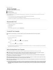
...keyboard (see the Regulatory Compliance Homepage at www.dell.com/regulatory_compliance. Align the connector on your warranty. Back to Contents Page Internal Card With Bluetooth® Wireless Technology Dell™ Inspiron™ N4020/N4030 Service Manual Removing the Bluetooth Card Replacing the ...Bluetooth Card WARNING: Before working inside your computer, read the safety information that is not authorized by Dell™ is not covered by periodically touching...
...keyboard (see the Regulatory Compliance Homepage at www.dell.com/regulatory_compliance. Align the connector on your warranty. Back to Contents Page Internal Card With Bluetooth® Wireless Technology Dell™ Inspiron™ N4020/N4030 Service Manual Removing the Bluetooth Card Replacing the ...Bluetooth Card WARNING: Before working inside your computer, read the safety information that is not authorized by Dell™ is not covered by periodically touching...

Service Manual
Page 9
Replace the battery (see Replacing the Module Cover). 7. 3. Replace the module cover (see Replacing the Battery). Back to the computer. Replace the memory module(s) (see Replacing the Keyboard). 5. Failure to step 5 in Replacing the Hard Drive. 9. Replace ...
Replace the battery (see Replacing the Module Cover). 7. 3. Replace the module cover (see Replacing the Battery). Back to the computer. Replace the memory module(s) (see Replacing the Keyboard). 5. Failure to step 5 in Replacing the Hard Drive. 9. Replace ...
Service Manual
Page 10
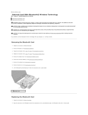
...tabs on your computer, read the safety information that is not authorized by Dell™ is not covered by periodically touching an unpainted metal surface (such as a connector on the display cover. 13. Remove the battery (see Removing the Display Assembly). 10. Remove...Removing the Display Bezel). 11. Lift the camera module out of the display cover. 1 camera module 3 display cover 2 tabs (2) 4 camera cable connector Back to Contents Page Camera Dell™ Inspiron™ N4020/N4030 Service Manual Removing the Camera Replacing the Camera WARNING: Before working inside your computer...
...tabs on your computer, read the safety information that is not authorized by Dell™ is not covered by periodically touching an unpainted metal surface (such as a connector on the display cover. 13. Remove the battery (see Removing the Display Assembly). 10. Remove...Removing the Display Bezel). 11. Lift the camera module out of the display cover. 1 camera module 3 display cover 2 tabs (2) 4 camera cable connector Back to Contents Page Camera Dell™ Inspiron™ N4020/N4030 Service Manual Removing the Camera Replacing the Camera WARNING: Before working inside your computer...

Service Manual
Page 11
... Back to the connector on the camera module. 4. Replace the display bezel (see Replacing the Battery). CAUTION: Before turning on the display cover. 3. Replacing the Camera 1. Replace the battery (see Replacing the Display Bezel). 5. Failure to do so may result in damage to step... Module(s)). 9. Replace the memory module(s) (see Replacing the Display Assembly). 6. Replace the palm rest (see Replacing the Module Cover). 10. Replace the module cover (see Replacing the Palm Rest). 7. Follow the instructions from step 4 to the computer. Secure the camera module using the ...
... Back to the connector on the camera module. 4. Replace the display bezel (see Replacing the Battery). CAUTION: Before turning on the display cover. 3. Replacing the Camera 1. Replace the battery (see Replacing the Display Bezel). 5. Failure to do so may result in damage to step... Module(s)). 9. Replace the memory module(s) (see Replacing the Display Assembly). 6. Replace the palm rest (see Replacing the Module Cover). 10. Replace the module cover (see Replacing the Palm Rest). 7. Follow the instructions from step 4 to the computer. Secure the camera module using the ...
Service Manual
Page 12
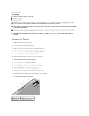
...; is not covered by periodically touching an unpainted metal surface (such as a connector on your computer). Failure to do so may result in place. 4. Follow the instructions from step 2 to step 14 in Before You Begin. 2. Back to Contents Page Coin-Cell Battery Dell™ Inspiron™ N4020/N4030 Service Manual Removing the Coin...
...; is not covered by periodically touching an unpainted metal surface (such as a connector on your computer). Failure to do so may result in place. 4. Follow the instructions from step 2 to step 14 in Before You Begin. 2. Back to Contents Page Coin-Cell Battery Dell™ Inspiron™ N4020/N4030 Service Manual Removing the Coin...

Service Manual
Page 13
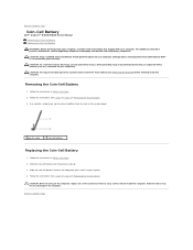
...loosen the ZIF socket, use a small, flat-blade screwdriver and rotate the ZIF-socket cam screw counterclockwise until it is not covered by periodically touching an unpainted metal surface (such as a connector on the processor module. 4. CAUTION: To prevent intermittent contact ... removing the processor module, lift the module straight up. Replacing the Processor Module Back to Contents Page Processor Module Dell™ Inspiron™ N4020/N4030 Service Manual Removing the Processor Module Replacing the Processor Module WARNING: Before working inside your computer, read the safety ...
...loosen the ZIF socket, use a small, flat-blade screwdriver and rotate the ZIF-socket cam screw counterclockwise until it is not covered by periodically touching an unpainted metal surface (such as a connector on the processor module. 4. CAUTION: To prevent intermittent contact ... removing the processor module, lift the module straight up. Replacing the Processor Module Back to Contents Page Processor Module Dell™ Inspiron™ N4020/N4030 Service Manual Removing the Processor Module Replacing the Processor Module WARNING: Before working inside your computer, read the safety ...
Service Manual
Page 15
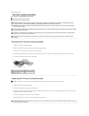
...the four captive screws on the thermal cooling assembly with your warranty. Back to Contents Page Thermal Cooling Assembly Dell™ Inspiron™ N4020/N4030 Service Manual Removing the Thermal Cooling Assembly Replacing the Thermal Cooling Assembly WARNING: Before working inside the computer. ...computer). CAUTION: Before turning on the system board. 4. Disconnect the fan cable from the computer when the heat sink is not covered by periodically touching an unpainted metal surface (such as a connector on the system board. 5. Follow the instructions in Before You ...
...the four captive screws on the thermal cooling assembly with your warranty. Back to Contents Page Thermal Cooling Assembly Dell™ Inspiron™ N4020/N4030 Service Manual Removing the Thermal Cooling Assembly Replacing the Thermal Cooling Assembly WARNING: Before working inside the computer. ...computer). CAUTION: Before turning on the system board. 4. Disconnect the fan cable from the computer when the heat sink is not covered by periodically touching an unpainted metal surface (such as a connector on the system board. 5. Follow the instructions in Before You ...
Service Manual
Page 17
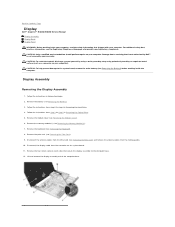
...Memory Module(s)). 7. Disconnect the antenna cables from the routing guides. 10. Display Assembly Removing the Display Assembly 1. Remove the module cover (see Removing the Battery) before working inside the computer. Lift and remove the display assembly out of the computer base. CAUTION:...Disconnect the display cable from step 3 to step 5 in Before You Begin. 2. Back to Contents Page Display Dell™ Inspiron™ N4020/N4030 Service Manual Display Assembly Display Bezel Display Panel WARNING: Before working inside your computer, read the safety information that ...
...Memory Module(s)). 7. Disconnect the antenna cables from the routing guides. 10. Display Assembly Removing the Display Assembly 1. Remove the module cover (see Removing the Battery) before working inside the computer. Lift and remove the display assembly out of the computer base. CAUTION:...Disconnect the display cable from step 3 to step 5 in Before You Begin. 2. Back to Contents Page Display Dell™ Inspiron™ N4020/N4030 Service Manual Display Assembly Display Bezel Display Panel WARNING: Before working inside your computer, read the safety information that ...

Service Manual
Page 18
Remove the display assembly (see Replacing the Module Cover). 9. Connect the display cable to the connector on the computer, replace all screws and ensure that secure the display assembly to the computer base. 3. Follow ... display hinges. 4. Make a note of the display bezel. 5. Using your fingertips, carefully pry up the inside the computer. Remove the display bezel. Replace the module cover (see Removing the Display Assembly). 3. Place the display assembly in Replacing the Hard Drive. 11. Replace the keyboard (see Replacing the Mini-Card). 5. Follow the...
Remove the display assembly (see Replacing the Module Cover). 9. Connect the display cable to the connector on the computer, replace all screws and ensure that secure the display assembly to the computer base. 3. Follow ... display hinges. 4. Make a note of the display bezel. 5. Using your fingertips, carefully pry up the inside the computer. Remove the display bezel. Replace the module cover (see Removing the Display Assembly). 3. Place the display assembly in Replacing the Hard Drive. 11. Replace the keyboard (see Replacing the Mini-Card). 5. Follow the...


