
Latitude E7280 Latitude Ultrabook E-Family Re-Image How-To Guide
Page 12
... Supported 3 @ 60Hz 4 Max Resolution 5120 x 2880 @ 60Hz USB Ports USB 2.0 - (2), USB 3.0 - (3) Thunderbolt 3 Port USB Type-C Extended Desktop. 2Dell Dock WD15 does not support wired vPro. Dell Latitude Ultrabook, E-Family & Mobile Precision Reimage "How-To" Guide Appendix D Dell Dock (WD15) & Dell Thunderbolt Dock (TB16) information Dell Dock WD15 Display Ports VGA, mDP, HDMI Number Displays Supported 2 1 Max Resolution 3840...
... Supported 3 @ 60Hz 4 Max Resolution 5120 x 2880 @ 60Hz USB Ports USB 2.0 - (2), USB 3.0 - (3) Thunderbolt 3 Port USB Type-C Extended Desktop. 2Dell Dock WD15 does not support wired vPro. Dell Latitude Ultrabook, E-Family & Mobile Precision Reimage "How-To" Guide Appendix D Dell Dock (WD15) & Dell Thunderbolt Dock (TB16) information Dell Dock WD15 Display Ports VGA, mDP, HDMI Number Displays Supported 2 1 Max Resolution 3840...

Latitude E7280 Latitude Ultrabook E-Family Re-Image How-To Guide
Page 13
... displays without having to plug each one into the laptop. See the TB16 user guide pg 22 The Dell Thunderbolt Dock TB16 is needed, the host Ethernet port can gain access to all your electronic devices to your peripherals such as a tied laptop accessory the dock.../Tablet MAC address 4 With Intel HD Integrated graphics. The host device must support Thunderbolt™ 3 for Thunderbolt speeds to be reduced to 30 Hz. Dell Latitude Ultrabook, E-Family & Mobile Precision Reimage "How-To" Guide Audio/Headphone 3.5 mm Combo - (1), 3.5 mm Speaker Out (1) Network RJ-45 Gigabit Ethernet...
... displays without having to plug each one into the laptop. See the TB16 user guide pg 22 The Dell Thunderbolt Dock TB16 is needed, the host Ethernet port can gain access to all your electronic devices to your peripherals such as a tied laptop accessory the dock.../Tablet MAC address 4 With Intel HD Integrated graphics. The host device must support Thunderbolt™ 3 for Thunderbolt speeds to be reduced to 30 Hz. Dell Latitude Ultrabook, E-Family & Mobile Precision Reimage "How-To" Guide Audio/Headphone 3.5 mm Combo - (1), 3.5 mm Speaker Out (1) Network RJ-45 Gigabit Ethernet...

Latitude E7280 Latitude Ultrabook E-Family Re-Image How-To Guide
Page 14
Frequently Asked Questions. For more information about USB Type-C, refer to 130w on supported computers only). Dell Latitude Ultrabook, E-Family & Mobile Precision Reimage "How-To" Guide Key Features: Supports up to three FHD displays or two 4K displays @ 60Hz Supports faster data transfer of up to 40 Gbps, ideal for large files. Common docking experience across platforms with USB-C port(s) having data, video, and power capabilities. Single cable for power and data (up to the knowledgebase article USB Type-C -
Frequently Asked Questions. For more information about USB Type-C, refer to 130w on supported computers only). Dell Latitude Ultrabook, E-Family & Mobile Precision Reimage "How-To" Guide Key Features: Supports up to three FHD displays or two 4K displays @ 60Hz Supports faster data transfer of up to 40 Gbps, ideal for large files. Common docking experience across platforms with USB-C port(s) having data, video, and power capabilities. Single cable for power and data (up to the knowledgebase article USB Type-C -
Owners Manual
Page 3
... module...19 Removing memory module...19 Installing memory module...20 Heat sink ...20 Removing heat sink assembly...20 Installing heat sink assembly...21 Power connector port...21 Removing power connector port...21 Contents 3 Windows 7...6 Before working inside your computer...6 Safety instructions...7 After working inside your computer -
... module...19 Removing memory module...19 Installing memory module...20 Heat sink ...20 Removing heat sink assembly...20 Installing heat sink assembly...21 Power connector port...21 Removing power connector port...21 Contents 3 Windows 7...6 Before working inside your computer...6 Safety instructions...7 After working inside your computer -

Owners Manual
Page 4
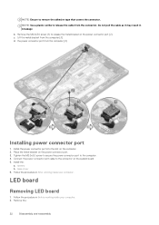
Installing power connector port...22 LED board...22 Removing LED board...22 Installing LED board...23 Smart card module...24 Removing smart card cage...24 Installing smart card cage...... System specifications...45 Memory specifications...45 Storage specifications...45 Video specifications...45 Audio specifications...45 Battery specifications...46 AC adapter specifications...46 Docking options...47 Port and connector specifications...47 Communication specifications...47 Camera specifications...48 Touchpad specifications...48 Display specifications...48 4 Contents
Installing power connector port...22 LED board...22 Removing LED board...22 Installing LED board...23 Smart card module...24 Removing smart card cage...24 Installing smart card cage...... System specifications...45 Memory specifications...45 Storage specifications...45 Video specifications...45 Audio specifications...45 Battery specifications...46 AC adapter specifications...46 Docking options...47 Port and connector specifications...47 Communication specifications...47 Camera specifications...48 Touchpad specifications...48 Display specifications...48 4 Contents
Owners Manual
Page 7
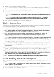
... a cable, ensure that is not covered by periodically touching an unpainted metal surface that both connectors are disconnecting this particular Dell computer. Some cables have read the safety information that shipped with your computer and all network cables from their electrical outlets.... sources before connecting to perform any cards, such as directed by a certified service technician. Connect any external devices, such as a port replicator or media base, and replace any disassembly tasks. Do not touch the components or contacts on the locking tabs before performing Step...
... a cable, ensure that is not covered by periodically touching an unpainted metal surface that both connectors are disconnecting this particular Dell computer. Some cables have read the safety information that shipped with your computer and all network cables from their electrical outlets.... sources before connecting to perform any cards, such as directed by a certified service technician. Connect any external devices, such as a port replicator or media base, and replace any disassembly tasks. Do not touch the components or contacts on the locking tabs before performing Step...

Owners Manual
Page 9
Latitude 7280 - 2 Disassembly and reassembly Screw size list Table 1. screw size list Component M2.5 x 6 Back cover Battery-3-cell Battery-4-cell SSD module Heat sink module System fan Speaker WWAN card WLAN card Power connector port ESD bracket EDP bracket Touchpad buttons Fingerprint reader LED board Smart card reader cage Keyboard Lock bracket Display hinge...
Latitude 7280 - 2 Disassembly and reassembly Screw size list Table 1. screw size list Component M2.5 x 6 Back cover Battery-3-cell Battery-4-cell SSD module Heat sink module System fan Speaker WWAN card WLAN card Power connector port ESD bracket EDP bracket Touchpad buttons Fingerprint reader LED board Smart card reader cage Keyboard Lock bracket Display hinge...
Owners Manual
Page 21
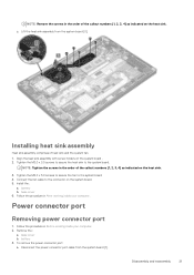
...Before working inside your computer. battery 3. To remove the power connector port: a. Lift the heat sink assembly from the system board [1]. base cover b. Disassembly and reassembly 21 Power connector port Removing power connector port 1. NOTE: Remove the screws in the order of the callout ... the heat sink. 3. Tighten the M2.0 x 5.0 screws to secure the fan to the system board. Remove the : a. Disconnect the power connector port cable from the system board [3]. c. Tighten the M2.0 x 3.0 screws to secure the heat sink to the system board 4. Install the : a. ...
...Before working inside your computer. battery 3. To remove the power connector port: a. Lift the heat sink assembly from the system board [1]. base cover b. Disassembly and reassembly 21 Power connector port Removing power connector port 1. NOTE: Remove the screws in the order of the callout ... the heat sink. 3. Tighten the M2.0 x 5.0 screws to secure the fan to the system board. Remove the : a. Disconnect the power connector port cable from the system board [3]. c. Tighten the M2.0 x 3.0 screws to secure the heat sink to the system board 4. Install the : a. ...
Owners Manual
Page 22
... release the cable from the connector. Follow the procedure in Before working inside your computer. Installing power connector port 1. base cover 6. the power connector port from the computer [3]. LED board Removing LED board 1. Do not pull the cable as it may result in After... working inside your computer. 2. Install the : a. NOTE: Ensure to release the metal bracket on the power connector port [2]. Remove the : 22 Disassembly and reassembly Lift the metal bracket from the computer [4]. Follow the procedure in breakage b. c. Remove the ...
... release the cable from the connector. Follow the procedure in Before working inside your computer. Installing power connector port 1. base cover 6. the power connector port from the computer [3]. LED board Removing LED board 1. Do not pull the cable as it may result in After... working inside your computer. 2. Install the : a. NOTE: Ensure to release the metal bracket on the power connector port [2]. Remove the : 22 Disassembly and reassembly Lift the metal bracket from the computer [4]. Follow the procedure in breakage b. c. Remove the ...

Owners Manual
Page 36
4. LED board cable [2] c. coin cell battery cable [3] d. power connector port cable [5] 36 Disassembly and reassembly speaker cable [1] b. To disconnect the cables: NOTE: To disconnect the speaker, LED board, coin cell battery and the power connector port cables, use a plastic scribe to release the cable from the connector. Do not pull the cable as it may result in breakage a. touchpad cable and USH board cable [4] e.
4. LED board cable [2] c. coin cell battery cable [3] d. power connector port cable [5] 36 Disassembly and reassembly speaker cable [1] b. To disconnect the cables: NOTE: To disconnect the speaker, LED board, coin cell battery and the power connector port cables, use a plastic scribe to release the cable from the connector. Do not pull the cable as it may result in breakage a. touchpad cable and USH board cable [4] e.

Owners Manual
Page 38
6. Remove the M2.0x5.0 screws that secure the USB Type-C bracket. 7. Flip the system board, peel off the tapes securing the bracket and remove the USB Type-C port from the system board. 38 Disassembly and reassembly
6. Remove the M2.0x5.0 screws that secure the USB Type-C bracket. 7. Flip the system board, peel off the tapes securing the bracket and remove the USB Type-C port from the system board. 38 Disassembly and reassembly

Owners Manual
Page 39
... If your computer. 2. WLAN card d. base cover 12. base cover b. Flip the system board and tighten the M2 x 3 screws to secure the USB type-C port to the computer. 6. Connect the speaker, power connector, LED board, touchpad, and USH cables to secure the Type-C bracket. 3. coin cell battery b. heat sink... the keyboard assembly. 1. battery c. Align the system board with the bracket in the slot on the system board. 7. Place the USB Type-C port along with the screw holders on the system board. 8. Connect the eDP cable to secure it . 9. SSD card f. Follow the procedure in ...
... If your computer. 2. WLAN card d. base cover 12. base cover b. Flip the system board and tighten the M2 x 3 screws to secure the USB type-C port to the computer. 6. Connect the speaker, power connector, LED board, touchpad, and USH cables to secure the Type-C bracket. 3. coin cell battery b. heat sink... the keyboard assembly. 1. battery c. Align the system board with the bracket in the slot on the system board. 7. Place the USB Type-C port along with the screw holders on the system board. 8. Connect the eDP cable to secure it . 9. SSD card f. Follow the procedure in ...

Owners Manual
Page 42
... component you are left with the screw holders on the keyboard tray. 2. base cover b. Installing keyboard to the keyboard tray. 3. battery c. system board m. power connector port h.
... component you are left with the screw holders on the keyboard tray. 2. base cover b. Installing keyboard to the keyboard tray. 3. battery c. system board m. power connector port h.

Owners Manual
Page 43
power connector port h. PCIe SSD k. base cover 5. system board c. memory l. keyboard b. speaker e. heatsink g. Follow the procedure in After working inside your computer. Disassembly and reassembly 43 4. WWAN card j. battery m. display assembly d. coin cell battery f. Install the: a. WLAN card i.
power connector port h. PCIe SSD k. base cover 5. system board c. memory l. keyboard b. speaker e. heatsink g. Follow the procedure in After working inside your computer. Disassembly and reassembly 43 4. WWAN card j. battery m. display assembly d. coin cell battery f. Install the: a. WLAN card i.

Owners Manual
Page 44
... specifications • AC adapter specifications • Docking options • Port and connector specifications • Communication specifications • Camera specifications • Touchpad specifications • Display specifications • Physical specifications • Environmental specifications Supported operating systems The topic lists the operating systems supported for Latitude 7280 system. Supported operating systems Supported operating systems Windows 10...
... specifications • AC adapter specifications • Docking options • Port and connector specifications • Communication specifications • Camera specifications • Touchpad specifications • Display specifications • Physical specifications • Environmental specifications Supported operating systems The topic lists the operating systems supported for Latitude 7280 system. Supported operating systems Supported operating systems Windows 10...

Owners Manual
Page 45
... 512 GB SATA SSD • Up to 1 TB PCIe NVMe SSD • Up to -analog System specifications 45 eDP (internal display), HDMI • Optional Type-C port - VGA, DisplayPort 1.2, DVI and Thunderbolt NOTE: Supports one M.2 SATA SSD or M.2 PCIe NVMe SSD.
... 512 GB SATA SSD • Up to 1 TB PCIe NVMe SSD • Up to -analog System specifications 45 eDP (internal display), HDMI • Optional Type-C port - VGA, DisplayPort 1.2, DVI and Thunderbolt NOTE: Supports one M.2 SATA SSD or M.2 PCIe NVMe SSD.

Owners Manual
Page 47
Options • Dell Dock WD15 • Dell Dock Stand DS1000 • Dell Thunderbolt Dock TB16 Port and connector specifications Feature Specification Audio Video Network adapter USB Microphone-in, stereo headphones, and headset combo connector HDMI 1.4 One RJ-45 connector • One ...
Options • Dell Dock WD15 • Dell Dock Stand DS1000 • Dell Thunderbolt Dock TB16 Port and connector specifications Feature Specification Audio Video Network adapter USB Microphone-in, stereo headphones, and headset combo connector HDMI 1.4 One RJ-45 connector • One ...

Owners Manual
Page 53
... Reporting Technology) specification. The options are : • Enable USB Boot Support-enabled by default • Enable the Thunderbolt ports-enabled by default • Always Allow dell docks-enabled by default • Enable External USB Port-enabled by default • Enable Thunderbolt Boot Support • Enable Thunderbolt (and PCIE behind TBT) Preboot • Security...
... Reporting Technology) specification. The options are : • Enable USB Boot Support-enabled by default • Enable the Thunderbolt ports-enabled by default • Always Allow dell docks-enabled by default • Enable External USB Port-enabled by default • Enable Thunderbolt Boot Support • Enable Thunderbolt (and PCIE behind TBT) Preboot • Security...

Owners Manual
Page 54
... always work in the system. Backlight Timeout Keyboard Illumination will continue to charge external devices using the stored system battery power through the USB PowerShare port. This option is enabled by default • 15 sec • 30 sec • 1 min • 5 min • 15 min • Never Keyboard The Keyboard Backlight...
... always work in the system. Backlight Timeout Keyboard Illumination will continue to charge external devices using the stored system battery power through the USB PowerShare port. This option is enabled by default • 15 sec • 30 sec • 1 min • 5 min • 15 min • Never Keyboard The Keyboard Backlight...

Owners Manual
Page 58
...7.5 Watts power • 15 Watts-enabled by default. • Primarily AC use • Custom If Custom Charge is connected. Wake on Dell USB-C dock Default setting: The option is disabled. Advanced Battery Charge Configuration This option enables you block entering to wake the system from all ... USB Wake Support Allows you to select the charging mode for all the USB ports to set the time at a standard rate. • ExpressCharge-The battery charges over a shorter time using Dell's fast charging technology This option is enabled by default 58 System Setup If the...
...7.5 Watts power • 15 Watts-enabled by default. • Primarily AC use • Custom If Custom Charge is connected. Wake on Dell USB-C dock Default setting: The option is disabled. Advanced Battery Charge Configuration This option enables you block entering to wake the system from all ... USB Wake Support Allows you to select the charging mode for all the USB ports to set the time at a standard rate. • ExpressCharge-The battery charges over a shorter time using Dell's fast charging technology This option is enabled by default 58 System Setup If the...


