
Service Manual
Page 3
... Corporation. Reproduction in any proprietary interest in this text: Dell, the DELL logo, and Latitude are trademarks of Dell Computer Corporation is subject to either the entities claiming the marks and names or their products. Dell Computer Corporation disclaims any manner whatsoever without notice. © 2000 Dell Computer Corporation. February 2000 P/N 64PTN Rev. Information in this...
... Corporation. Reproduction in any proprietary interest in this text: Dell, the DELL logo, and Latitude are trademarks of Dell Computer Corporation is subject to either the entities claiming the marks and names or their products. Dell Computer Corporation disclaims any manner whatsoever without notice. © 2000 Dell Computer Corporation. February 2000 P/N 64PTN Rev. Information in this...

Service Manual
Page 4
Recommended Tools 2 Preparing to Work Inside Your Computer 2 Before Working Inside Your Computer 2 Screw Identification 3 Disconnecting Interface Connectors 5 Removing a Cable from a ZIF Interface Connector 5 Replacing a Cable into a ZIF Interface Connector 5 Field-Replaceable Parts and Assemblies 6 Removing and Replacing Field-Replaceable Parts and Assemblies 10 Hard-Disk Drive Assembly 11 Removing the Hard-Disk Drive Assembly 11 Replacing the Hard-Disk Drive Assembly 11 Modular Bay Devices (Diskette Drive, CD-ROM Drive, DVD-ROM Drive, CD-RW Drive, SuperDisk LS-120 Drive, Battery,...
Recommended Tools 2 Preparing to Work Inside Your Computer 2 Before Working Inside Your Computer 2 Screw Identification 3 Disconnecting Interface Connectors 5 Removing a Cable from a ZIF Interface Connector 5 Replacing a Cable into a ZIF Interface Connector 5 Field-Replaceable Parts and Assemblies 6 Removing and Replacing Field-Replaceable Parts and Assemblies 10 Hard-Disk Drive Assembly 11 Removing the Hard-Disk Drive Assembly 11 Replacing the Hard-Disk Drive Assembly 11 Modular Bay Devices (Diskette Drive, CD-ROM Drive, DVD-ROM Drive, CD-RW Drive, SuperDisk LS-120 Drive, Battery,...

Service Manual
Page 5
Figure 4. Figure 15. Figure 19. Figure 8. Figure 7. Figure 10. Figure 13. Figure 16. Figure 14. Figure 3. Figure 5. Figure 12. Figure 17. Figure 11. Figure 18. 12.1-Inch Display Assembly Bezel and LCD Panel 25 Removing the 12.1-Inch Display Assembly Bezel 25 Removing the 12.1-Inch LCD Panel Inverter 26 Removing the 12.1-Inch LCD Flex Cable 26 Replacing the 12.1-Inch LCD Flex Cable 26 Replacing the 12.1-Inch LCD Panel Inverter 27 Replacing the 12.1-Inch LCD Panel 28 Display Assembly Latch 29 Palmrest Assembly 30 Removing the Palmrest Assembly 30 Reserve Battery...
Figure 4. Figure 15. Figure 19. Figure 8. Figure 7. Figure 10. Figure 13. Figure 16. Figure 14. Figure 3. Figure 5. Figure 12. Figure 17. Figure 11. Figure 18. 12.1-Inch Display Assembly Bezel and LCD Panel 25 Removing the 12.1-Inch Display Assembly Bezel 25 Removing the 12.1-Inch LCD Panel Inverter 26 Removing the 12.1-Inch LCD Flex Cable 26 Replacing the 12.1-Inch LCD Flex Cable 26 Replacing the 12.1-Inch LCD Panel Inverter 27 Replacing the 12.1-Inch LCD Panel 28 Display Assembly Latch 29 Palmrest Assembly 30 Removing the Palmrest Assembly 30 Reserve Battery...

Service Manual
Page 6
Table 2. Figure 24. Palmrest Assembly Removal 31 Modem Assembly 33 System Board Assembly 35 Thermal Cooling Assembly Removal 36 Module Latch Assemblies Removal 37 Left Module Latch and Spring 38 Table 1. Figure 25. Figure 21. Figure 22. Figure 23. Figure 20. Screw Placement Mat With Component Screw Counts and Sizes 4 Parts and Assemblies 6 vii
Table 2. Figure 24. Palmrest Assembly Removal 31 Modem Assembly 33 System Board Assembly 35 Thermal Cooling Assembly Removal 36 Module Latch Assemblies Removal 37 Left Module Latch and Spring 38 Table 1. Figure 25. Figure 21. Figure 22. Figure 23. Figure 20. Screw Placement Mat With Component Screw Counts and Sizes 4 Parts and Assemblies 6 vii

Service Manual
Page 7
A prerequisite for troubleshooting procedures and instructions on using this manual to information provided in PC troubleshooting techniques. In addition to service Dell computer systems is a basic knowledge of text may be accompanied by an icon and printed in bold type or in italic type. ...viii Throughout this guide, blocks of PCs and prior training in this manual, Dell provides the User's Guide for using the Dell Diagnostics to test the computer system. These blocks are notes, notices, and cautions, and they are used as follows: NOTE:...
A prerequisite for troubleshooting procedures and instructions on using this manual to information provided in PC troubleshooting techniques. In addition to service Dell computer systems is a basic knowledge of text may be accompanied by an icon and printed in bold type or in italic type. ...viii Throughout this guide, blocks of PCs and prior training in this manual, Dell provides the User's Guide for using the Dell Diagnostics to test the computer system. These blocks are notes, notices, and cautions, and they are used as follows: NOTE:...

Service Manual
Page 8
.... It is recommended that a part can be allowed to exceed 180 degrees. The angle of computer support.dell.com Dell Latitude CPt V/CPt S Series and CPx H/CPx J Series Service Manual 1 Unless otherwise noted, each procedure in your Dell Latitude portable computer. This manual provides instructions for removing and replacing field-replaceable components, assemblies, and subassemblies in this...
.... It is recommended that a part can be allowed to exceed 180 degrees. The angle of computer support.dell.com Dell Latitude CPt V/CPt S Series and CPx H/CPx J Series Service Manual 1 Unless otherwise noted, each procedure in your Dell Latitude portable computer. This manual provides instructions for removing and replacing field-replaceable components, assemblies, and subassemblies in this...
Service Manual
Page 9
Also disconnect any work in suspend-to reduce the potential for 4 seconds. 3. NOTE: Make sure the computer is docked in the modular device bay. 2 Dell Latitude CPt V/CPt S Series and CPx H/CPx J Series Service Manual Save any telephone or telecommunications lines from their electrical outlets to -disk or hibernate mode. Disconnect the computer and any...
Also disconnect any work in suspend-to reduce the potential for 4 seconds. 3. NOTE: Make sure the computer is docked in the modular device bay. 2 Dell Latitude CPt V/CPt S Series and CPx H/CPx J Series Service Manual Save any telephone or telecommunications lines from their electrical outlets to -disk or hibernate mode. Disconnect the computer and any...

Service Manual
Page 10
... of the screw's label. A graphic for correct length. M2.5x20 M2.5x10 M3.0x5 M2.5x4 M2.5x4 M3.0x3 M2.0x3 support.dell.com Dell Latitude CPt V/CPt S Series and CPx H/CPx J Series Service Manual 3 Slide the battery bay latch toward the right side of the battery bay (see Figure 2). Remove the main battery...
... of the screw's label. A graphic for correct length. M2.5x20 M2.5x10 M3.0x5 M2.5x4 M2.5x4 M3.0x3 M2.0x3 support.dell.com Dell Latitude CPt V/CPt S Series and CPx H/CPx J Series Service Manual 3 Slide the battery bay latch toward the right side of the battery bay (see Figure 2). Remove the main battery...

Service Manual
Page 11
... are removing and replacing components, photocopy the Table 1 placement mat as a tool to your system) Thermal Cooling Assembly and Exhaust Fan: M2.5 x 4 (2 each) 4 Dell Latitude CPt V/CPt S Series and CPx H/CPx J Series Service Manual Hard-Disk Drive Assembly: M3.0 x 5 (1 each) Keyboard Assembly: M2.5 x 10 (7 each) Display Assembly: M2.5 x 4 (3 each) Display Assembly Bezel: Rubber Screw...
... are removing and replacing components, photocopy the Table 1 placement mat as a tool to your system) Thermal Cooling Assembly and Exhaust Fan: M2.5 x 4 (2 each) 4 Dell Latitude CPt V/CPt S Series and CPx H/CPx J Series Service Manual Hard-Disk Drive Assembly: M3.0 x 5 (1 each) Keyboard Assembly: M2.5 x 10 (7 each) Display Assembly: M2.5 x 4 (3 each) Display Assembly Bezel: Rubber Screw...

Service Manual
Page 12
... computer's interface connectors are not removable, but they must be released to open the movable part of the cable into the connector. 3. support.dell.com Dell Latitude CPt V/CPt S Series and CPx H/CPx J Series Service Manual 5 Push gently sideways on the movable part of connector (do not remove) 1. These connectors are zero insertion force (ZIF...
... computer's interface connectors are not removable, but they must be released to open the movable part of the cable into the connector. 3. support.dell.com Dell Latitude CPt V/CPt S Series and CPx H/CPx J Series Service Manual 5 Push gently sideways on the movable part of connector (do not remove) 1. These connectors are zero insertion force (ZIF...

Service Manual
Page 13
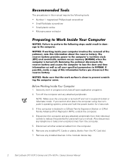
The subsections that follow Table 2 provide instructions for the manufacturer's name. 6 Dell Latitude CPt V/CPt S Series and CPx H/CPx J Series Service Manual CUS, ADPT, AC, EXT, 20V, 70W, NBK ADPT, AC, EXT, 20V, 70W, 3W, BA CORD, PWR, 110V, 6F, AC, 3W/3P, US ...
The subsections that follow Table 2 provide instructions for the manufacturer's name. 6 Dell Latitude CPt V/CPt S Series and CPx H/CPx J Series Service Manual CUS, ADPT, AC, EXT, 20V, 70W, NBK ADPT, AC, EXT, 20V, 70W, 3W, BA CORD, PWR, 110V, 6F, AC, 3W/3P, US ...

Service Manual
Page 14
... 14.1-inch flex cable ASSY, CBL, FLX, TFT 12.1-inch flex cable ASSY, CBL, FLX, W/EXTN,12.1 14 14 16 16 14 16, 17 support.dell.com Dell Latitude CPt V/CPt S Series and CPx H/CPx J Series Service Manual 7
... 14.1-inch flex cable ASSY, CBL, FLX, TFT 12.1-inch flex cable ASSY, CBL, FLX, W/EXTN,12.1 14 14 16 16 14 16, 17 support.dell.com Dell Latitude CPt V/CPt S Series and CPx H/CPx J Series Service Manual 7

Service Manual
Page 15
...-MB CUS, 128MB, DIMM, SDRAM Customer kit, memory module, 192-MB CUS, 192MB, DIMM, SDRAM Customer kit, memory module, 256-MB CUS, 256MB, DIMM, SDRAM 8 Dell Latitude CPt V/CPt S Series and CPx H/CPx J Series Service Manual
...-MB CUS, 128MB, DIMM, SDRAM Customer kit, memory module, 192-MB CUS, 192MB, DIMM, SDRAM Customer kit, memory module, 256-MB CUS, 256MB, DIMM, SDRAM 8 Dell Latitude CPt V/CPt S Series and CPx H/CPx J Series Service Manual
Service Manual
Page 16
... Kit, latch, slider, Button Foot, Rubber, Black (4 each) Foot, Rubber, Strike Zone, Black LTCH, BTN, Module Foot, Rbr, Blk Foot, Rbr, Strike Zone, Blk support.dell.com Dell Latitude CPt V/CPt S Series and CPx H/CPx J Series Service Manual 9
... Kit, latch, slider, Button Foot, Rubber, Black (4 each) Foot, Rubber, Strike Zone, Black LTCH, BTN, Module Foot, Rbr, Blk Foot, Rbr, Strike Zone, Blk support.dell.com Dell Latitude CPt V/CPt S Series and CPx H/CPx J Series Service Manual 9

Service Manual
Page 17
display assembly keyboard palmrest assembly hard-disk drive internal modem (may not apply to your system) system board main battery case plug for modem bottom case assembly modular bay device The following subsections provide instructions for removing and replacing field-replaceable parts and assemblies. 10 Dell Latitude CPt V/CPt S Series and CPx H/CPx J Series Service Manual
display assembly keyboard palmrest assembly hard-disk drive internal modem (may not apply to your system) system board main battery case plug for modem bottom case assembly modular bay device The following subsections provide instructions for removing and replacing field-replaceable parts and assemblies. 10 Dell Latitude CPt V/CPt S Series and CPx H/CPx J Series Service Manual

Service Manual
Page 18
... drive door. bottom of the computer. 1. Turn the computer over , and remove the 5-mm screw from the center of the computer. 2. support.dell.com Dell Latitude CPt V/CPt S Series and CPx H/CPx J Series Service Manual 11 Remove the main battery and secondary battery (if present). 2. Slide the drive door up and pull the drive assembly...
... drive door. bottom of the computer. 1. Turn the computer over , and remove the 5-mm screw from the center of the computer. 2. support.dell.com Dell Latitude CPt V/CPt S Series and CPx H/CPx J Series Service Manual 11 Remove the main battery and secondary battery (if present). 2. Slide the drive door up and pull the drive assembly...

Service Manual
Page 19
... with the other hand (see Figure 7). 1. Insert a flat-blade screwdriver under the indentation in the bottom case assembly and lift the cover. 12 Dell Latitude CPt V/CPt S Series and CPx H/CPx J Series Service Manual Close the display, and turn the computer upside down on a flat work surface. 2. Release the memory module cover. Push the...
... with the other hand (see Figure 7). 1. Insert a flat-blade screwdriver under the indentation in the bottom case assembly and lift the cover. 12 Dell Latitude CPt V/CPt S Series and CPx H/CPx J Series Service Manual Close the display, and turn the computer upside down on a flat work surface. 2. Release the memory module cover. Push the...

Service Manual
Page 20
support.dell.com Dell Latitude CPt V/CPt S Series and CPx H/CPx J Series Service Manual 13 they are notched so that the memory module is inserted with the double-stacked memory chips facing down does not fit ...
support.dell.com Dell Latitude CPt V/CPt S Series and CPx H/CPx J Series Service Manual 13 they are notched so that the memory module is inserted with the double-stacked memory chips facing down does not fit ...

Service Manual
Page 21
... hear a click as each end of the memory module socket. Pivot the memory module down on a flat work surface. 10-mm screws (7) M2.5x10 14 Dell Latitude CPt V/CPt S Series and CPx H/CPx J Series Service Manual
... hear a click as each end of the memory module socket. Pivot the memory module down on a flat work surface. 10-mm screws (7) M2.5x10 14 Dell Latitude CPt V/CPt S Series and CPx H/CPx J Series Service Manual

Service Manual
Page 22
3. track stick keyboard scalloped edge of the palmrest. 7. Lift the keyboard out of blank key palmrest 6. support.dell.com Dell Latitude CPt V/CPt S Series and CPx H/CPx J Series Service Manual 15 Turn the computer right-side up and open the display. 5. Release the keyboard from the palmrest assembly by inserting a small flat-...
3. track stick keyboard scalloped edge of the palmrest. 7. Lift the keyboard out of blank key palmrest 6. support.dell.com Dell Latitude CPt V/CPt S Series and CPx H/CPx J Series Service Manual 15 Turn the computer right-side up and open the display. 5. Release the keyboard from the palmrest assembly by inserting a small flat-...
