
Service Manual
Page 4
...-ROM Drive, DVD-ROM Drive, CD-RW Drive, SuperDisk LS-120 Drive, Battery, or Travel Module) . . . . 12 Memory Module Cover 12 Removing the Memory Module Cover 12 Memory Modules 13 Removing the Memory Modules 13 Replacing the Memory Modules 13 Keyboard Assembly 14 Removing the Keyboard Assembly 14 Replacing the Keyboard Assembly 16 Microprocessor Module...
...-ROM Drive, DVD-ROM Drive, CD-RW Drive, SuperDisk LS-120 Drive, Battery, or Travel Module) . . . . 12 Memory Module Cover 12 Removing the Memory Module Cover 12 Memory Modules 13 Removing the Memory Modules 13 Replacing the Memory Modules 13 Keyboard Assembly 14 Removing the Keyboard Assembly 14 Replacing the Keyboard Assembly 16 Microprocessor Module...

Service Manual
Page 5
... Battery Removal 3 Screw Identification 3 Disconnecting a Cable from an Interface Connector 5 Exploded View-Computer 10 Hard-Disk Drive Assembly Removal 11 Modular Bay Device Removal 12 Memory Module Removal 13 Removing the Keyboard Assembly Screws 14 Keyboard Assembly Removal 15 Keyboard and Track Stick Cables and Connectors 16 Microprocessor Module Removal 18...
... Battery Removal 3 Screw Identification 3 Disconnecting a Cable from an Interface Connector 5 Exploded View-Computer 10 Hard-Disk Drive Assembly Removal 11 Modular Bay Device Removal 12 Memory Module Removal 13 Removing the Keyboard Assembly Screws 14 Keyboard Assembly Removal 15 Keyboard and Track Stick Cables and Connectors 16 Microprocessor Module Removal 18...

Service Manual
Page 15
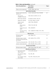
... Customer kit, memory CUS, 32MB, DIMM, SDRAM 8 module, 32-MB Customer kit, memory module, 64-MB CUS, 64MB, DIMM, SDRAM Customer kit, memory module, 128-MB CUS, 128MB, DIMM, SDRAM Customer kit, memory module, 192-MB CUS, 192MB, DIMM, SDRAM Customer kit, memory module, 256-MB CUS, 256MB, DIMM, SDRAM 8 Dell Latitude CPt V/CPt S Series and CPx H/CPx J Series...
... Customer kit, memory CUS, 32MB, DIMM, SDRAM 8 module, 32-MB Customer kit, memory module, 64-MB CUS, 64MB, DIMM, SDRAM Customer kit, memory module, 128-MB CUS, 128MB, DIMM, SDRAM Customer kit, memory module, 192-MB CUS, 192MB, DIMM, SDRAM Customer kit, memory module, 256-MB CUS, 256MB, DIMM, SDRAM 8 Dell Latitude CPt V/CPt S Series and CPx H/CPx J Series...
Service Manual
Page 16
Memory door assembly DOOR, MEM, MET, NB System board assembly, SVCKIT, MB ASSY, PWA, ENGINE 22 service kit Service tag installation diskette DSK, BIOS, FLDSVC, F3, ... Kit, latch, slider, Button Foot, Rubber, Black (4 each) Foot, Rubber, Strike Zone, Black LTCH, BTN, Module Foot, Rbr, Blk Foot, Rbr, Strike Zone, Blk support.dell.com Dell Latitude CPt V/CPt S Series and CPx H/CPx J Series Service Manual 9
Memory door assembly DOOR, MEM, MET, NB System board assembly, SVCKIT, MB ASSY, PWA, ENGINE 22 service kit Service tag installation diskette DSK, BIOS, FLDSVC, F3, ... Kit, latch, slider, Button Foot, Rubber, Black (4 each) Foot, Rubber, Strike Zone, Black LTCH, BTN, Module Foot, Rbr, Blk Foot, Rbr, Strike Zone, Blk support.dell.com Dell Latitude CPt V/CPt S Series and CPx H/CPx J Series Service Manual 9

Service Manual
Page 19
... surface. 2. Insert a flat-blade screwdriver under the indentation in the bottom case assembly and lift the cover. 12 Dell Latitude CPt V/CPt S Series and CPx H/CPx J Series Service Manual Close the display, and turn the computer upside down on a flat work surface. 3. Release the memory module cover. Push the module latch toward the unlock icon.
... surface. 2. Insert a flat-blade screwdriver under the indentation in the bottom case assembly and lift the cover. 12 Dell Latitude CPt V/CPt S Series and CPx H/CPx J Series Service Manual Close the display, and turn the computer upside down on a flat work surface. 3. Release the memory module cover. Push the module latch toward the unlock icon.

Service Manual
Page 20
... facing down does not fit properly in only one way. Remove the memory module cover. 3. NOTES: 192-MB memory modules are not interchangeable. inner tabs (2 per socket) memory module sockets (2) DIMM A DIMM B 1. Remove the main battery and secondary battery (if present). 2. If you . support.dell.com Dell Latitude CPt V/CPt S Series and CPx H/CPx J Series Service Manual 13
... facing down does not fit properly in only one way. Remove the memory module cover. 3. NOTES: 192-MB memory modules are not interchangeable. inner tabs (2 per socket) memory module sockets (2) DIMM A DIMM B 1. Remove the main battery and secondary battery (if present). 2. If you . support.dell.com Dell Latitude CPt V/CPt S Series and CPx H/CPx J Series Service Manual 13

Service Manual
Page 21
..., and turn the computer upside down until it . 4. Replace the memory module cover. 1. Remove the main battery and secondary battery (if present). 2. Pivot the memory module down on a flat work surface. 10-mm screws (7) M2.5x10 14 Dell Latitude CPt V/CPt S Series and CPx H/CPx J Series Service Manual With the module at a 45-degree angle, press...
..., and turn the computer upside down until it . 4. Replace the memory module cover. 1. Remove the main battery and secondary battery (if present). 2. Pivot the memory module down on a flat work surface. 10-mm screws (7) M2.5x10 14 Dell Latitude CPt V/CPt S Series and CPx H/CPx J Series Service Manual With the module at a 45-degree angle, press...

Service Manual
Page 42
.... 4. Replace the modular bay devices and any PC Cards or plastic blanks in the PC Card slot. 6. support.dell.com Dell Latitude CPt V/CPt S Series and CPx H/CPx J Series Service Manual 35 Lift the system board assembly out of the replacement system board assembly. Replace the modem (...if present). 3. Follow the instructions on the computer. Install the replacement system board. 2. NOTE: Be sure to transfer the memory...
.... 4. Replace the modular bay devices and any PC Cards or plastic blanks in the PC Card slot. 6. support.dell.com Dell Latitude CPt V/CPt S Series and CPx H/CPx J Series Service Manual 35 Lift the system board assembly out of the replacement system board assembly. Replace the modem (...if present). 3. Follow the instructions on the computer. Install the replacement system board. 2. NOTE: Be sure to transfer the memory...

Service Manual
Page 47
... bay devices removal, 12 module latch assemblies removal, 37 screw identification and tightening, 3 sockets memory module, 13 SuperDisk LS-120 drive removal, 12 system board assembly removal, 18 thermal cooling assembly removal, 36 tools, 2 travel module removal, 12 ZIF connectors, 5 palmrest assembly removal, 30 2 Dell Latitude CPt V/CPt S Series and CPx H/Cpx J Series Service Manual
... bay devices removal, 12 module latch assemblies removal, 37 screw identification and tightening, 3 sockets memory module, 13 SuperDisk LS-120 drive removal, 12 system board assembly removal, 18 thermal cooling assembly removal, 36 tools, 2 travel module removal, 12 ZIF connectors, 5 palmrest assembly removal, 30 2 Dell Latitude CPt V/CPt S Series and CPx H/Cpx J Series Service Manual


