
Service Manual
Page 8
It is open nearly 180 degrees. The angle of computer support.dell.com Dell Latitude CPt V/CPt S Series and CPx H/CPx J Series Service Manual 1 Also, when performing the procedures in reverse order. This manual provides instructions for removing and replacing field-replaceable components, assemblies, and subassemblies in Figure 1 unless otherwise specified. back of computer left side right side front...
It is open nearly 180 degrees. The angle of computer support.dell.com Dell Latitude CPt V/CPt S Series and CPx H/CPx J Series Service Manual 1 Also, when performing the procedures in reverse order. This manual provides instructions for removing and replacing field-replaceable components, assemblies, and subassemblies in Figure 1 unless otherwise specified. back of computer left side right side front...
Service Manual
Page 9
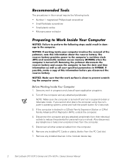
The procedures in the modular device bay. 2 Dell Latitude CPt V/CPt S Series and CPx H/CPx J Series Service Manual NOTE: Make sure the computer is docked in a C/Dock Family Expansion Station or C/Port Family Advanced Port Replicator (APR), undock the computer. 4. If... any attached peripherals from the computer. 5. Remove any installed PC Cards or plastic blanks from the computer. 6. Remove any installed devices in this manual require the following tools: Number 1 magnetized Phillips-head screwdriver Small flat-blade screwdriver Small plastic scribe Microprocessor extractor 1.
The procedures in the modular device bay. 2 Dell Latitude CPt V/CPt S Series and CPx H/CPx J Series Service Manual NOTE: Make sure the computer is docked in a C/Dock Family Expansion Station or C/Port Family Advanced Port Replicator (APR), undock the computer. 4. If... any attached peripherals from the computer. 5. Remove any installed PC Cards or plastic blanks from the computer. 6. Remove any installed devices in this manual require the following tools: Number 1 magnetized Phillips-head screwdriver Small flat-blade screwdriver Small plastic scribe Microprocessor extractor 1.

Service Manual
Page 10
... provide the correct screw length as part of the computer. M2.5x20 M2.5x10 M3.0x5 M2.5x4 M2.5x4 M3.0x3 M2.0x3 support.dell.com Dell Latitude CPt V/CPt S Series and CPx H/CPx J Series Service Manual 3 While you work, periodically touch the I /O panel on the back of the screw's label.
... provide the correct screw length as part of the computer. M2.5x20 M2.5x10 M3.0x5 M2.5x4 M2.5x4 M3.0x3 M2.0x3 support.dell.com Dell Latitude CPt V/CPt S Series and CPx H/CPx J Series Service Manual 3 While you work, periodically touch the I /O panel on the back of the screw's label.

Service Manual
Page 11
...) System Board Assembly: M2.5 x 4 (2 each) (w/o modem assembly) M2.5 x 4 (1 each) M2.5 x 10 (1 each) (w/ modem assembly) Microprocessor Shield Assembly: 3 captive and 2 removable screws M2.0 x 3 (2 each) M2.5 x 4 (1 each ) 4 Dell Latitude CPt V/CPt S Series and CPx H/CPx J Series Service Manual
...) System Board Assembly: M2.5 x 4 (2 each) (w/o modem assembly) M2.5 x 4 (1 each) M2.5 x 10 (1 each) (w/ modem assembly) Microprocessor Shield Assembly: 3 captive and 2 removable screws M2.0 x 3 (2 each) M2.5 x 4 (1 each ) 4 Dell Latitude CPt V/CPt S Series and CPx H/CPx J Series Service Manual

Service Manual
Page 12
movable part of the cable into the connector. 3. Grasp the interface cable and pull it releases the interface cable. 3. support.dell.com Dell Latitude CPt V/CPt S Series and CPx H/CPx J Series Service Manual 5 Use a small flat-blade screwdriver to disconnect the cable from them (see Figure 4). While holding the cable in place, close the ZIF connector. Some of...
movable part of the cable into the connector. 3. Grasp the interface cable and pull it releases the interface cable. 3. support.dell.com Dell Latitude CPt V/CPt S Series and CPx H/CPx J Series Service Manual 5 Use a small flat-blade screwdriver to disconnect the cable from them (see Figure 4). While holding the cable in place, close the ZIF connector. Some of...

Service Manual
Page 13
... or assembly and are provided for the computer. The subsections that follow Table 2 provide instructions for the manufacturer's name. 6 Dell Latitude CPt V/CPt S Series and CPx H/CPx J Series Service Manual CUS, ADPT, AC, EXT, 20V, 70W, NBK ADPT, AC, EXT, 20V, 70W, 3W, BA CORD, PWR, 110V, 6F, AC, 3W/3P, US Customer kit, main ...
... or assembly and are provided for the computer. The subsections that follow Table 2 provide instructions for the manufacturer's name. 6 Dell Latitude CPt V/CPt S Series and CPx H/CPx J Series Service Manual CUS, ADPT, AC, EXT, 20V, 70W, NBK ADPT, AC, EXT, 20V, 70W, 3W, BA CORD, PWR, 110V, 6F, AC, 3W/3P, US Customer kit, main ...

Service Manual
Page 14
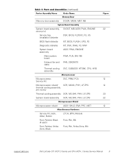
... 14.1-inch flex cable ASSY, CBL, FLX, TFT 12.1-inch flex cable ASSY, CBL, FLX, W/EXTN,12.1 14 14 16 16 14 16, 17 support.dell.com Dell Latitude CPt V/CPt S Series and CPx H/CPx J Series Service Manual 7
... 14.1-inch flex cable ASSY, CBL, FLX, TFT 12.1-inch flex cable ASSY, CBL, FLX, W/EXTN,12.1 14 14 16 16 14 16, 17 support.dell.com Dell Latitude CPt V/CPt S Series and CPx H/CPx J Series Service Manual 7

Service Manual
Page 15
...-MB CUS, 128MB, DIMM, SDRAM Customer kit, memory module, 192-MB CUS, 192MB, DIMM, SDRAM Customer kit, memory module, 256-MB CUS, 256MB, DIMM, SDRAM 8 Dell Latitude CPt V/CPt S Series and CPx H/CPx J Series Service Manual
...-MB CUS, 128MB, DIMM, SDRAM Customer kit, memory module, 192-MB CUS, 192MB, DIMM, SDRAM Customer kit, memory module, 256-MB CUS, 256MB, DIMM, SDRAM 8 Dell Latitude CPt V/CPt S Series and CPx H/CPx J Series Service Manual
Service Manual
Page 16
...0M, NB Exhaust fan and FAN, 25X25X10 cable Thermal cooling SVC, SUBASSY, HTSNK, CPU, HYB assembly Microprocessor, SVC, PRM, PCA 12 Service Kit Microprocessor shield/ SCR, M2X3, PHH, LP, ZPS 12 thermal cooling assembly arm screw Thermal cooling assembly SCR, M2.5X4, PHH,... LP, ZPS 22 Microprocessor shield ASSY, SHLD, EMI, PRC, MET 12 Service Kit, latch, slider, Button Foot, Rubber, Black (4 each) Foot, Rubber, Strike Zone, Black LTCH, BTN, Module Foot, Rbr, Blk Foot, Rbr, Strike Zone, Blk support.dell.com Dell Latitude CPt V/CPt S Series and CPx H/CPx J Series Service Manual 9
...0M, NB Exhaust fan and FAN, 25X25X10 cable Thermal cooling SVC, SUBASSY, HTSNK, CPU, HYB assembly Microprocessor, SVC, PRM, PCA 12 Service Kit Microprocessor shield/ SCR, M2X3, PHH, LP, ZPS 12 thermal cooling assembly arm screw Thermal cooling assembly SCR, M2.5X4, PHH,... LP, ZPS 22 Microprocessor shield ASSY, SHLD, EMI, PRC, MET 12 Service Kit, latch, slider, Button Foot, Rubber, Black (4 each) Foot, Rubber, Strike Zone, Black LTCH, BTN, Module Foot, Rbr, Blk Foot, Rbr, Strike Zone, Blk support.dell.com Dell Latitude CPt V/CPt S Series and CPx H/CPx J Series Service Manual 9

Service Manual
Page 17
display assembly keyboard palmrest assembly hard-disk drive internal modem (may not apply to your system) system board main battery case plug for modem bottom case assembly modular bay device The following subsections provide instructions for removing and replacing field-replaceable parts and assemblies. 10 Dell Latitude CPt V/CPt S Series and CPx H/CPx J Series Service Manual
display assembly keyboard palmrest assembly hard-disk drive internal modem (may not apply to your system) system board main battery case plug for modem bottom case assembly modular bay device The following subsections provide instructions for removing and replacing field-replaceable parts and assemblies. 10 Dell Latitude CPt V/CPt S Series and CPx H/CPx J Series Service Manual

Service Manual
Page 18
... present). 2. Turn the computer over , and remove the 5-mm screw from the center of the hard-disk drive door (see Figure 6). support.dell.com Dell Latitude CPt V/CPt S Series and CPx H/CPx J Series Service Manual 11 Slide the drive door up and pull the drive assembly out of the computer. 3. Push the drive assembly into the opening...
... present). 2. Turn the computer over , and remove the 5-mm screw from the center of the hard-disk drive door (see Figure 6). support.dell.com Dell Latitude CPt V/CPt S Series and CPx H/CPx J Series Service Manual 11 Slide the drive door up and pull the drive assembly out of the computer. 3. Push the drive assembly into the opening...

Service Manual
Page 19
Insert a flat-blade screwdriver under the indentation in the bottom case assembly and lift the cover. 12 Dell Latitude CPt V/CPt S Series and CPx H/CPx J Series Service Manual latch lock 1. Keep holding the latch open while pulling the device out of the modular bay with the other hand (see Figure 7). 1. Close the display, ...
Insert a flat-blade screwdriver under the indentation in the bottom case assembly and lift the cover. 12 Dell Latitude CPt V/CPt S Series and CPx H/CPx J Series Service Manual latch lock 1. Keep holding the latch open while pulling the device out of the modular bay with the other hand (see Figure 7). 1. Close the display, ...

Service Manual
Page 20
Be sure that the memory module can be firmly seated only one way. support.dell.com Dell Latitude CPt V/CPt S Series and CPx H/CPx J Series Service Manual 13 The module should pop up slightly (see Figure 8). 4. NOTES: 192-MB memory modules are keyed, or designed to disengage from its socket. 1. A 192-MB ...
Be sure that the memory module can be firmly seated only one way. support.dell.com Dell Latitude CPt V/CPt S Series and CPx H/CPx J Series Service Manual 13 The module should pop up slightly (see Figure 8). 4. NOTES: 192-MB memory modules are keyed, or designed to disengage from its socket. 1. A 192-MB ...

Service Manual
Page 21
Pivot the memory module down on a flat work surface. 10-mm screws (7) M2.5x10 14 Dell Latitude CPt V/CPt S Series and CPx H/CPx J Series Service Manual Remove the main battery and secondary battery (if present). 2. With the module at a 45-degree angle, press the memory module's edge connector firmly into place. ...
Pivot the memory module down on a flat work surface. 10-mm screws (7) M2.5x10 14 Dell Latitude CPt V/CPt S Series and CPx H/CPx J Series Service Manual Remove the main battery and secondary battery (if present). 2. With the module at a 45-degree angle, press the memory module's edge connector firmly into place. ...

Service Manual
Page 22
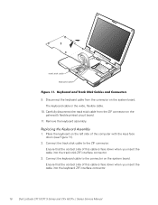
... Figure 10), and lift the right edge of the blank key (see Figure 9). 4. track stick keyboard scalloped edge of the palmrest. 7. support.dell.com Dell Latitude CPt V/CPt S Series and CPx H/CPx J Series Service Manual 15 Rest the key face of the keyboard on the left edge of the computer. Rotate the keyboard over the left side...
... Figure 10), and lift the right edge of the blank key (see Figure 9). 4. track stick keyboard scalloped edge of the palmrest. 7. support.dell.com Dell Latitude CPt V/CPt S Series and CPx H/CPx J Series Service Manual 15 Rest the key face of the keyboard on the left edge of the computer. Rotate the keyboard over the left side...
Service Manual
Page 23
... the left side of the computer with the keys face down when you insert the cable into the keyboard ZIF interface connector. 16 Dell Latitude CPt V/CPt S Series and CPx H/CPx J Series Service Manual Ensure that the contact side of this cable is the wide, flexible cable. 10. track stick cable keyboard cable 9. Ensure that the...
... the left side of the computer with the keys face down when you insert the cable into the keyboard ZIF interface connector. 16 Dell Latitude CPt V/CPt S Series and CPx H/CPx J Series Service Manual Ensure that the contact side of this cable is the wide, flexible cable. 10. track stick cable keyboard cable 9. Ensure that the...

Service Manual
Page 24
support.dell.com Dell Latitude CPt V/CPt S Series and CPx H/CPx J Series Service Manual 17 Carefully turn the computer over and fit the keyboard into the palmrest. 5. The keys should be flush with the left and right sides of ...
support.dell.com Dell Latitude CPt V/CPt S Series and CPx H/CPx J Series Service Manual 17 Carefully turn the computer over and fit the keyboard into the palmrest. 5. The keys should be flush with the left and right sides of ...
Service Manual
Page 25
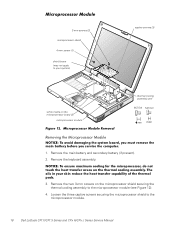
... screw (1) shield brace (may not apply to your system) white marks on the microprocessor shield securing the thermal cooling assembly to the microprocessor module. 18 Dell Latitude CPt V/CPt S Series and CPx H/CPx J Series Service Manual
... screw (1) shield brace (may not apply to your system) white marks on the microprocessor shield securing the thermal cooling assembly to the microprocessor module. 18 Dell Latitude CPt V/CPt S Series and CPx H/CPx J Series Service Manual

Service Manual
Page 26
... the microprocessor module is fully seated, apply pressure over the connector. Rotate the arm of the processor board (see Figure 12). 1. support.dell.com Dell Latitude CPt V/CPt S Series and CPx H/CPx J Series Service Manual 19 Rotate the arm of the module are higher than the others, the module is fully seated, all four corners are aligned...
... the microprocessor module is fully seated, apply pressure over the connector. Rotate the arm of the processor board (see Figure 12). 1. support.dell.com Dell Latitude CPt V/CPt S Series and CPx H/CPx J Series Service Manual 19 Rotate the arm of the module are higher than the others, the module is fully seated, all four corners are aligned...

Service Manual
Page 27
... the seam from the back of the computer (see Figure 13). NOTE: Always remove and replace the LCD panel as a complete assembly. 20 Dell Latitude CPt V/CPt S Series and CPx H/CPx J Series Service Manual display assembly hinge cover LCD flex cable snap tab bottom case assembly 4-mm screws (3) snap tab M2.5x4 1. Remove the keyboard. 3. Remove...
... the seam from the back of the computer (see Figure 13). NOTE: Always remove and replace the LCD panel as a complete assembly. 20 Dell Latitude CPt V/CPt S Series and CPx H/CPx J Series Service Manual display assembly hinge cover LCD flex cable snap tab bottom case assembly 4-mm screws (3) snap tab M2.5x4 1. Remove the keyboard. 3. Remove...


