
Service Manual
Page 7
... in bold type or in PC troubleshooting techniques. In addition to information provided in this manual, Dell provides the User's Guide for using the Dell Diagnostics to service Dell computer systems is a basic knowledge of your computer. viii A prerequisite for troubleshooting procedures ...and instructions on using this manual to test the computer system. These blocks are notes, notices, and cautions, and ...
... in bold type or in PC troubleshooting techniques. In addition to information provided in this manual, Dell provides the User's Guide for using the Dell Diagnostics to service Dell computer systems is a basic knowledge of your computer. viii A prerequisite for troubleshooting procedures ...and instructions on using this manual to test the computer system. These blocks are notes, notices, and cautions, and ...

Service Manual
Page 8
... should never be replaced by performing the removal procedure in Figure 1 unless otherwise specified. Also, when performing the procedures in this manual assumes that you use a book or something similar to the computer are as shown in reverse order. This... or directions relative to support the display assembly when it is open nearly 180 degrees. The angle of computer support.dell.com Dell Latitude CPt V/CPt S Series and CPx H/CPx J Series Service Manual 1 back of computer left side right side front of the display assembly with respect to exceed 180 degrees. Unless ...
... should never be replaced by performing the removal procedure in Figure 1 unless otherwise specified. Also, when performing the procedures in this manual assumes that you use a book or something similar to the computer are as shown in reverse order. This... or directions relative to support the display assembly when it is open nearly 180 degrees. The angle of computer support.dell.com Dell Latitude CPt V/CPt S Series and CPx H/CPx J Series Service Manual 1 back of computer left side right side front of the display assembly with respect to exceed 180 degrees. Unless ...
Service Manual
Page 9
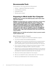
...close all other external cables from the PC Card slot. 7. Remove any work in the modular device bay. 2 Dell Latitude CPt V/CPt S Series and CPx H/CPx J Series Service Manual If you cannot shut down the computer using the computer's operating system, press and hold the power button for ...personal injury or shock. NOTE: Make sure the computer is docked in this manual require the following tools: Number 1 magnetized...
...close all other external cables from the PC Card slot. 7. Remove any work in the modular device bay. 2 Dell Latitude CPt V/CPt S Series and CPx H/CPx J Series Service Manual If you cannot shut down the computer using the computer's operating system, press and hold the power button for ...personal injury or shock. NOTE: Make sure the computer is docked in this manual require the following tools: Number 1 magnetized...

Service Manual
Page 10
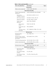
... right side of the screw's label. A graphic for correct length. M2.5x20 M2.5x10 M3.0x5 M2.5x4 M2.5x4 M3.0x3 M2.0x3 support.dell.com Dell Latitude CPt V/CPt S Series and CPx H/CPx J Series Service Manual 3 The illustrations in the illustration.
... right side of the screw's label. A graphic for correct length. M2.5x20 M2.5x10 M3.0x5 M2.5x4 M2.5x4 M3.0x3 M2.0x3 support.dell.com Dell Latitude CPt V/CPt S Series and CPx H/CPx J Series Service Manual 3 The illustrations in the illustration.

Service Manual
Page 11
...: M2.5 x 4 (2 each) (w/o modem assembly) M2.5 x 4 (1 each) M2.5 x 10 (1 each) (w/ modem assembly) Microprocessor Shield Assembly: 3 captive and 2 removable screws M2.0 x 3 (2 each) M2.5 x 4 (1 each ) 4 Dell Latitude CPt V/CPt S Series and CPx H/CPx J Series Service Manual When you are removing and replacing components, photocopy the Table 1 placement mat as a tool to your system) Thermal Cooling Assembly and Exhaust...
...: M2.5 x 4 (2 each) (w/o modem assembly) M2.5 x 4 (1 each) M2.5 x 10 (1 each) (w/ modem assembly) Microprocessor Shield Assembly: 3 captive and 2 removable screws M2.0 x 3 (2 each) M2.5 x 4 (1 each ) 4 Dell Latitude CPt V/CPt S Series and CPx H/CPx J Series Service Manual When you are removing and replacing components, photocopy the Table 1 placement mat as a tool to your system) Thermal Cooling Assembly and Exhaust...

Service Manual
Page 12
.... 3. Grasp the interface cable and pull it releases the interface cable. 3. movable part of the connector. 1. These connectors are zero insertion force (ZIF) connectors. support.dell.com Dell Latitude CPt V/CPt S Series and CPx H/CPx J Series Service Manual 5
.... 3. Grasp the interface cable and pull it releases the interface cable. 3. movable part of the connector. 1. These connectors are zero insertion force (ZIF) connectors. support.dell.com Dell Latitude CPt V/CPt S Series and CPx H/CPx J Series Service Manual 5

Service Manual
Page 13
... Power cable, U.S. Some parts may only be available as part of a service kit or assembly and are provided for the manufacturer's name. 6 Dell Latitude CPt V/CPt S Series and CPx H/CPx J Series Service Manual The subsections that follow Table 2 provide instructions for the computer. Table 2 lists the parts and assemblies available for removing and replacing these...
... Power cable, U.S. Some parts may only be available as part of a service kit or assembly and are provided for the manufacturer's name. 6 Dell Latitude CPt V/CPt S Series and CPx H/CPx J Series Service Manual The subsections that follow Table 2 provide instructions for the computer. Table 2 lists the parts and assemblies available for removing and replacing these...

Service Manual
Page 14
... 14.1-inch flex cable ASSY, CBL, FLX, TFT 12.1-inch flex cable ASSY, CBL, FLX, W/EXTN,12.1 14 14 16 16 14 16, 17 support.dell.com Dell Latitude CPt V/CPt S Series and CPx H/CPx J Series Service Manual 7
... 14.1-inch flex cable ASSY, CBL, FLX, TFT 12.1-inch flex cable ASSY, CBL, FLX, W/EXTN,12.1 14 14 16 16 14 16, 17 support.dell.com Dell Latitude CPt V/CPt S Series and CPx H/CPx J Series Service Manual 7

Service Manual
Page 15
...-MB CUS, 128MB, DIMM, SDRAM Customer kit, memory module, 192-MB CUS, 192MB, DIMM, SDRAM Customer kit, memory module, 256-MB CUS, 256MB, DIMM, SDRAM 8 Dell Latitude CPt V/CPt S Series and CPx H/CPx J Series Service Manual
...-MB CUS, 128MB, DIMM, SDRAM Customer kit, memory module, 192-MB CUS, 192MB, DIMM, SDRAM Customer kit, memory module, 256-MB CUS, 256MB, DIMM, SDRAM 8 Dell Latitude CPt V/CPt S Series and CPx H/CPx J Series Service Manual
Service Manual
Page 16
... Kit, latch, slider, Button Foot, Rubber, Black (4 each) Foot, Rubber, Strike Zone, Black LTCH, BTN, Module Foot, Rbr, Blk Foot, Rbr, Strike Zone, Blk support.dell.com Dell Latitude CPt V/CPt S Series and CPx H/CPx J Series Service Manual 9
... Kit, latch, slider, Button Foot, Rubber, Black (4 each) Foot, Rubber, Strike Zone, Black LTCH, BTN, Module Foot, Rbr, Blk Foot, Rbr, Strike Zone, Blk support.dell.com Dell Latitude CPt V/CPt S Series and CPx H/CPx J Series Service Manual 9

Service Manual
Page 17
display assembly keyboard palmrest assembly hard-disk drive internal modem (may not apply to your system) system board main battery case plug for modem bottom case assembly modular bay device The following subsections provide instructions for removing and replacing field-replaceable parts and assemblies. 10 Dell Latitude CPt V/CPt S Series and CPx H/CPx J Series Service Manual
display assembly keyboard palmrest assembly hard-disk drive internal modem (may not apply to your system) system board main battery case plug for modem bottom case assembly modular bay device The following subsections provide instructions for removing and replacing field-replaceable parts and assemblies. 10 Dell Latitude CPt V/CPt S Series and CPx H/CPx J Series Service Manual

Service Manual
Page 18
Remove the main battery and secondary battery (if present). 2. support.dell.com Dell Latitude CPt V/CPt S Series and CPx H/CPx J Series Service Manual 11 Slide the drive door up and pull the drive assembly out of computer 5-mm screw M3.0x5 hard-disk drive door 1. Push the drive ...
Remove the main battery and secondary battery (if present). 2. support.dell.com Dell Latitude CPt V/CPt S Series and CPx H/CPx J Series Service Manual 11 Slide the drive door up and pull the drive assembly out of computer 5-mm screw M3.0x5 hard-disk drive door 1. Push the drive ...

Service Manual
Page 19
... down on a flat work surface. 2. Insert a flat-blade screwdriver under the indentation in the bottom case assembly and lift the cover. 12 Dell Latitude CPt V/CPt S Series and CPx H/CPx J Series Service Manual Keep holding the latch open while pulling the device out of the modular bay with the other hand (see Figure 7). 1. Close the...
... down on a flat work surface. 2. Insert a flat-blade screwdriver under the indentation in the bottom case assembly and lift the cover. 12 Dell Latitude CPt V/CPt S Series and CPx H/CPx J Series Service Manual Keep holding the latch open while pulling the device out of the modular bay with the other hand (see Figure 7). 1. Close the...

Service Manual
Page 20
... are designed for the memory module to fit into their sockets, in only one memory module, install it in the socket. support.dell.com Dell Latitude CPt V/CPt S Series and CPx H/CPx J Series Service Manual 13 they are keyed, or designed to disengage from its socket, carefully spread apart the inner tabs of its socket. 1. Remove...
... are designed for the memory module to fit into their sockets, in only one memory module, install it in the socket. support.dell.com Dell Latitude CPt V/CPt S Series and CPx H/CPx J Series Service Manual 13 they are keyed, or designed to disengage from its socket, carefully spread apart the inner tabs of its socket. 1. Remove...

Service Manual
Page 21
... each end of the memory module socket. Pivot the memory module down on a flat work surface. 10-mm screws (7) M2.5x10 14 Dell Latitude CPt V/CPt S Series and CPx H/CPx J Series Service Manual With the module at a 45-degree angle, press the memory module's edge connector firmly into place. Replace the memory module cover. 1. Close...
... each end of the memory module socket. Pivot the memory module down on a flat work surface. 10-mm screws (7) M2.5x10 14 Dell Latitude CPt V/CPt S Series and CPx H/CPx J Series Service Manual With the module at a 45-degree angle, press the memory module's edge connector firmly into place. Replace the memory module cover. 1. Close...

Service Manual
Page 22
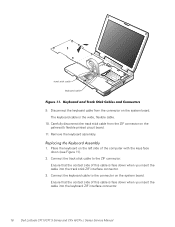
... palmrest 6. Release the keyboard from the palmrest assembly by inserting a small flat-blade screwdriver under the edge of the keyboard. support.dell.com Dell Latitude CPt V/CPt S Series and CPx H/CPx J Series Service Manual 15 track stick keyboard scalloped edge of the palmrest. 7. Rest the key face of the keyboard on the left edge of the...
... palmrest 6. Release the keyboard from the palmrest assembly by inserting a small flat-blade screwdriver under the edge of the keyboard. support.dell.com Dell Latitude CPt V/CPt S Series and CPx H/CPx J Series Service Manual 15 track stick keyboard scalloped edge of the palmrest. 7. Rest the key face of the keyboard on the left edge of the...
Service Manual
Page 23
... on the left side of this cable is face down when you insert the cable into the keyboard ZIF interface connector. 16 Dell Latitude CPt V/CPt S Series and CPx H/CPx J Series Service Manual Connect the keyboard cable to the ZIF connector. Remove the keyboard assembly. 1. Place the keyboard on the palmrest's flexible printed circuit board...
... on the left side of this cable is face down when you insert the cable into the keyboard ZIF interface connector. 16 Dell Latitude CPt V/CPt S Series and CPx H/CPx J Series Service Manual Connect the keyboard cable to the ZIF connector. Remove the keyboard assembly. 1. Place the keyboard on the palmrest's flexible printed circuit board...

Service Manual
Page 24
... keys should be flush with the left and right sides of the palmrest. 7. Ensure that the keyboard is correctly installed. support.dell.com Dell Latitude CPt V/CPt S Series and CPx H/CPx J Series Service Manual 17 Carefully turn the computer over and fit the keyboard into the palmrest. 5. To push the keyboard down, press on the left...
... keys should be flush with the left and right sides of the palmrest. 7. Ensure that the keyboard is correctly installed. support.dell.com Dell Latitude CPt V/CPt S Series and CPx H/CPx J Series Service Manual 17 Carefully turn the computer over and fit the keyboard into the palmrest. 5. To push the keyboard down, press on the left...
Service Manual
Page 25
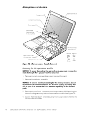
... screw (1) shield brace (may not apply to your system) white marks on the microprocessor shield securing the thermal cooling assembly to the microprocessor module. 18 Dell Latitude CPt V/CPt S Series and CPx H/CPx J Series Service Manual
... screw (1) shield brace (may not apply to your system) white marks on the microprocessor shield securing the thermal cooling assembly to the microprocessor module. 18 Dell Latitude CPt V/CPt S Series and CPx H/CPx J Series Service Manual

Service Manual
Page 26
... the microprocessor module is fully seated, all four corners are higher than the others, the module is not seated correctly. 2. support.dell.com Dell Latitude CPt V/CPt S Series and CPx H/CPx J Series Service Manual 19 Rotate the arm of the thermal cooling assembly into place. 4. Replace the two 3-mm screws that secures the microprocessor shield brace...
... the microprocessor module is fully seated, all four corners are higher than the others, the module is not seated correctly. 2. support.dell.com Dell Latitude CPt V/CPt S Series and CPx H/CPx J Series Service Manual 19 Rotate the arm of the thermal cooling assembly into place. 4. Replace the two 3-mm screws that secures the microprocessor shield brace...


