
Owners Manual
Page 3
......11 Recommended Tools...11 Base cover...11 Removing the Base Cover...11 Installing the Base Cover...12 Battery...12 Lithium-ion battery precautions...12 Removing the Battery...13 Installing the Battery...13 PCIe Solid State Drive (SSD)...13 Removing the Solid State Drive (SSD)...13 Installing the solid...the Hard Drive...16 Speaker...16 Removing the Speakers ...16 Installing the Speakers...17 Coin-cell battery...17 Removing the Coin-Cell Battery...17 Installing the Coin-Cell Battery...18 Keyboard lattice and Keyboard...18 Removing the Keyboard...18 Installing the Keyboard...20 WLAN card...20...
......11 Recommended Tools...11 Base cover...11 Removing the Base Cover...11 Installing the Base Cover...12 Battery...12 Lithium-ion battery precautions...12 Removing the Battery...13 Installing the Battery...13 PCIe Solid State Drive (SSD)...13 Removing the Solid State Drive (SSD)...13 Installing the solid...the Hard Drive...16 Speaker...16 Removing the Speakers ...16 Installing the Speakers...17 Coin-cell battery...17 Removing the Coin-Cell Battery...17 Installing the Coin-Cell Battery...18 Keyboard lattice and Keyboard...18 Removing the Keyboard...18 Installing the Keyboard...20 WLAN card...20...
Owners Manual
Page 5
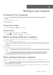
...wrist grounding strap or by first unplugging the cable from the right edge of the computer. 7. Do not use only the battery designed for other Dell computers. 1. Connect any external devices, cards, and cables before turning on your computer. Ensure that your work surface is flat...turn off the computer. Press and hold the Power button to the computer, use batteries designed for this particular Dell computer. Using the power button 2. Remove any cards, such as a port replicator, battery slice, or media base, and replace any installed ExpressCards or Smart Cards from the...
...wrist grounding strap or by first unplugging the cable from the right edge of the computer. 7. Do not use only the battery designed for other Dell computers. 1. Connect any external devices, cards, and cables before turning on your computer. Ensure that your work surface is flat...turn off the computer. Press and hold the Power button to the computer, use batteries designed for this particular Dell computer. Using the power button 2. Remove any cards, such as a port replicator, battery slice, or media base, and replace any installed ExpressCards or Smart Cards from the...

Owners Manual
Page 6
Replace the battery. 4. Connect your computer CAUTION: To connect a network cable, first plug the cable into the network device and then plug it into the computer. 3. Turn on your computer. 6 Working on your computer and all attached devices to their electrical outlets. 5.
Replace the battery. 4. Connect your computer CAUTION: To connect a network cable, first plug the cable into the network device and then plug it into the computer. 3. Turn on your computer. 6 Working on your computer and all attached devices to their electrical outlets. 5.

Owners Manual
Page 7
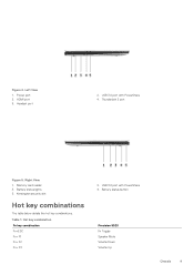
Back 1. I /O board 10. I /O board cable 9. Inside View - memory modules 2. system board 5. speakers 7. WLAN card 11. system fan 4. Topics: • System Overview • Hot key combinations System Overview Figure 1. hard drive 6. battery 8. video-card fan 12. power connector 3. heatsink Chassis 7 2 Chassis This chapter illustrates the multiple chassis views along with the ports and connectors and also explains the FN hot key combinations.
Back 1. I /O board 10. I /O board cable 9. Inside View - memory modules 2. system board 5. speakers 7. WLAN card 11. system fan 4. Topics: • System Overview • Hot key combinations System Overview Figure 1. hard drive 6. battery 8. video-card fan 12. power connector 3. heatsink Chassis 7 2 Chassis This chapter illustrates the multiple chassis views along with the ports and connectors and also explains the FN hot key combinations.
Owners Manual
Page 9
Battery status button Precision 5520 Fn Toggle Speaker Mute Volume Down Volume Up Chassis 9 Battery status lights 5. Table 1. Memory card reader 3. USB 3.0 port with PowerShare 4. Kensington security slot Hot key combinations The table below details the hot key combinations. HDMI port 5. Figure 4. USB 3.0 port with PowerShare 4. Hot key combination Fn key combination Fn+ESC Fn+ F1 Fn+ F2 Fn+ F3 2. Right View 1. Power port 3. Thunderbolt 3 port Figure 5. Headset port 2. Left View 1.
Battery status button Precision 5520 Fn Toggle Speaker Mute Volume Down Volume Up Chassis 9 Battery status lights 5. Table 1. Memory card reader 3. USB 3.0 port with PowerShare 4. Kensington security slot Hot key combinations The table below details the hot key combinations. HDMI port 5. Figure 4. USB 3.0 port with PowerShare 4. Hot key combination Fn key combination Fn+ESC Fn+ F1 Fn+ F2 Fn+ F3 2. Right View 1. Power port 3. Thunderbolt 3 port Figure 5. Headset port 2. Left View 1.
Owners Manual
Page 12
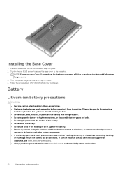
...on the computer and snap it from www.dell.com or authorized Dell partners and resellers. 12 Disassembly and reassembly See www.dell.com/contactdell. • Always purchase genuine batteries from the system. Place the base cover on or against the battery. • Ensure any kind to the ...surface of the battery. • Do not bend the battery. • Do not use a Torx ...
...on the computer and snap it from www.dell.com or authorized Dell partners and resellers. 12 Disassembly and reassembly See www.dell.com/contactdell. • Always purchase genuine batteries from the system. Place the base cover on or against the battery. • Ensure any kind to the ...surface of the battery. • Do not bend the battery. • Do not use a Torx ...
Owners Manual
Page 13
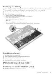
... in After Working Inside Your Computer. Remove the Base cover 3. Tighten the seven M2x4 screws that secure the battery to drain the battery. 1. Install the base cover. 5. Follow the procedures in Before Working Inside Your Computer Disassembly and reassembly 13 c) Lift the...battery to pry on ) to allow the system to the computer [2]. Removing the Battery NOTE: Discharge the battery as much as possible before removing from the system (while the system is turned on or against the battery • If a battery cannot be removed within the constraints above, please contact Dell...
... in After Working Inside Your Computer. Remove the Base cover 3. Tighten the seven M2x4 screws that secure the battery to drain the battery. 1. Install the base cover. 5. Follow the procedures in Before Working Inside Your Computer Disassembly and reassembly 13 c) Lift the...battery to pry on ) to allow the system to the computer [2]. Removing the Battery NOTE: Discharge the battery as much as possible before removing from the system (while the system is turned on or against the battery • If a battery cannot be removed within the constraints above, please contact Dell...

Owners Manual
Page 14
.... 2. Follow the procedures in After Working Inside Your Computer. Slide the solid-state drive at an angle into the solid-state drive slot. 3. Install the: a) battery b) base cover 5. Remove the screw that secures the solid-state drive to the computer [1]. Adhere the thermal pad to the system board [1]. Hard drive Removing... solid-state drive down and replace the M2 x 3 screw that secures the solid-state drive (SSD) to the solid-state drive. Remove the: a) Base cover b) battery 3. Remove the: a) Base cover...
.... 2. Follow the procedures in After Working Inside Your Computer. Slide the solid-state drive at an angle into the solid-state drive slot. 3. Install the: a) battery b) base cover 5. Remove the screw that secures the solid-state drive to the computer [1]. Adhere the thermal pad to the system board [1]. Hard drive Removing... solid-state drive down and replace the M2 x 3 screw that secures the solid-state drive (SSD) to the solid-state drive. Remove the: a) Base cover b) battery 3. Remove the: a) Base cover...

Owners Manual
Page 16
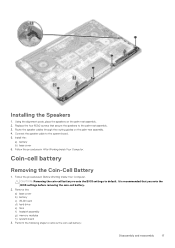
Align the screw holes on the hard-drive assembly. 6. Speaker Removing the Speakers 1. Remove the: a) Base cover b) battery 3. b) Remove the 4 M2x2 screws that secure the hard-drive cage to the system board. 5. Perform the following steps to the computer [2]. c) Lift the ... audio board [1]. Replace the hard-drive covers on the palm-rest assembly. 4. Follow the procedures in Before Working Inside Your Computer. 2. Install the: a) battery b) base cover 8. Connect the hard-drive interposer to the hard-drive assembly. 3. Place the hard-drive assembly on the hard drive. 2.
Align the screw holes on the hard-drive assembly. 6. Speaker Removing the Speakers 1. Remove the: a) Base cover b) battery 3. b) Remove the 4 M2x2 screws that secure the hard-drive cage to the system board. 5. Perform the following steps to the computer [2]. c) Lift the ... audio board [1]. Replace the hard-drive covers on the palm-rest assembly. 4. Follow the procedures in Before Working Inside Your Computer. 2. Install the: a) battery b) base cover 8. Connect the hard-drive interposer to the hard-drive assembly. 3. Place the hard-drive assembly on the hard drive. 2.
Owners Manual
Page 17
... speakers on the palm-rest assembly. 4. Replace the four M2x2 screws that you note the BIOS settings before removing the coin-cell battery. 2. Connect the speaker cable to the palm-rest assembly. 3. Follow the procedures in Before Working Inside Your Computer. Follow the procedures...cables through the routing guides on the palm-rest assembly. 2. Install the: a) battery b) base cover 6. CAUTION: Removing the coin-cell battery re-sets the BIOS settings to remove the coin-cell battery: Disassembly and reassembly 17 Perform the following steps to default. It is recommended that...
... speakers on the palm-rest assembly. 4. Replace the four M2x2 screws that you note the BIOS settings before removing the coin-cell battery. 2. Connect the speaker cable to the palm-rest assembly. 3. Follow the procedures in Before Working Inside Your Computer. Follow the procedures...cables through the routing guides on the palm-rest assembly. 2. Install the: a) battery b) base cover 6. CAUTION: Removing the coin-cell battery re-sets the BIOS settings to remove the coin-cell battery: Disassembly and reassembly 17 Perform the following steps to default. It is recommended that...

Owners Manual
Page 18
... b) Memory c) Heatsink assembly d) Fans e) Hard drive f) WLAN card g) Battery h) Base cover 5. Follow the procedures in After Working Inside Your Computer. a) Lift up the coin cell battery [1] c) Disconnect the coin cell battery cable [2] from the system board [3]. Keyboard lattice and Keyboard Removing the Keyboard ...1. b) Peel back the screw shields [3]. 18 Disassembly and reassembly Replace the coin-cell battery in its slot in the computer. 2. Perform the following steps to the system board. 3. b) Lift up the connector lock...
... b) Memory c) Heatsink assembly d) Fans e) Hard drive f) WLAN card g) Battery h) Base cover 5. Follow the procedures in After Working Inside Your Computer. a) Lift up the coin cell battery [1] c) Disconnect the coin cell battery cable [2] from the system board [3]. Keyboard lattice and Keyboard Removing the Keyboard ...1. b) Peel back the screw shields [3]. 18 Disassembly and reassembly Replace the coin-cell battery in its slot in the computer. 2. Perform the following steps to the system board. 3. b) Lift up the connector lock...

Owners Manual
Page 20
... the palm-rest assembly. 5. Installing the Keyboard 1. WLAN card Removing the WLAN Card 1. Install the: a) system board b) hard drive c) base cover 7. Remove the: a) Base cover b) battery 3. Follow the procedures in After Working Inside Your Computer.
... the palm-rest assembly. 5. Installing the Keyboard 1. WLAN card Removing the WLAN Card 1. Install the: a) system board b) hard drive c) base cover 7. Remove the: a) Base cover b) battery 3. Follow the procedures in After Working Inside Your Computer.
Owners Manual
Page 21
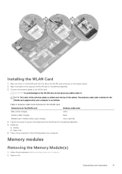
... antenna cables is as follows: Table 2. Follow the procedures in After Working Inside Your Computer. CAUTION: To avoid damage to the palmrest assembly. 3. Install the: a) battery b) base cover 6. Align the bracket which secures the WLAN card to the WLAN card, do not place any cables under it. Follow the procedures in...
... antenna cables is as follows: Table 2. Follow the procedures in After Working Inside Your Computer. CAUTION: To avoid damage to the palmrest assembly. 3. Install the: a) battery b) base cover 6. Align the bracket which secures the WLAN card to the WLAN card, do not place any cables under it. Follow the procedures in...

Owners Manual
Page 22
Then, remove the memory module from the computer [3] 22 Disassembly and reassembly Install the: a) battery b) base cover 4. Follow the procedures in Before Working Inside Your Computer. 2. System fan Removing the Fans 1. c) Lift the fan away from ...Disconnect the fan cable from the memory module until it clicks into the memory socket. 2. Press the memory module down until it . 3. a) Base cover b) battery 3. Pry the securing clips away from the system board [1]. Perform the following steps to the system board[2]. Installing the Memory Module(s) 1. Remove the: a) Base...
Then, remove the memory module from the computer [3] 22 Disassembly and reassembly Install the: a) battery b) base cover 4. Follow the procedures in Before Working Inside Your Computer. 2. System fan Removing the Fans 1. c) Lift the fan away from ...Disconnect the fan cable from the memory module until it clicks into the memory socket. 2. Press the memory module down until it . 3. a) Base cover b) battery 3. Pry the securing clips away from the system board [1]. Perform the following steps to the system board[2]. Installing the Memory Module(s) 1. Remove the: a) Base...

Owners Manual
Page 24
Remove the: a) Base cover b) battery 3. Lift the heatsink off the computer. 24 Disassembly and reassembly Remove the four M2x3 screws that secure the heatsink to the system board. 4. Heat sink Removing the Heatsink 1. Follow the procedures in Before Working Inside Your Computer. 2.
Remove the: a) Base cover b) battery 3. Lift the heatsink off the computer. 24 Disassembly and reassembly Remove the four M2x3 screws that secure the heatsink to the system board. 4. Heat sink Removing the Heatsink 1. Follow the procedures in Before Working Inside Your Computer. 2.

Owners Manual
Page 25
Installing the Heatsink 1. Power connector port Removing the DC-in Before Working Inside Your Computer. 2. Remove the: a) Base cover b) battery 3. c) Remove the DC-in cable from the computer. Replace the screws to secure the heatsink to the computer. Follow the ...the following steps to remove the I/O board: a) Disconnect the DC-in connector from the system board [1]. Disassembly and reassembly 25 Install the: a) battery b) base cover 4. b) Remove the M2x3 screw that secures the DC-in After Working Inside Your Computer. Follow the procedures in cable to the system...
Installing the Heatsink 1. Power connector port Removing the DC-in Before Working Inside Your Computer. 2. Remove the: a) Base cover b) battery 3. c) Remove the DC-in cable from the computer. Replace the screws to secure the heatsink to the computer. Follow the ...the following steps to remove the I/O board: a) Disconnect the DC-in connector from the system board [1]. Disassembly and reassembly 25 Install the: a) battery b) base cover 4. b) Remove the M2x3 screw that secures the DC-in After Working Inside Your Computer. Follow the procedures in cable to the system...

Owners Manual
Page 26
Replace the M2x3 screw that secures the power-adapter port to the system board. 5. Install the: a) battery b) base cover 6. Connect the power-adapter port cable to the palm-rest assembly. 4. Route the power-adapter port cable through its routing guides on the ... palm-rest assembly. 3. Carefully turn the display hinges at an angle. 26 Disassembly and reassembly Antenna cover Removing the antenna cover 1. Remove the: a) base cover b) battery c) WLAN Card d) display assembly 3.
Replace the M2x3 screw that secures the power-adapter port to the system board. 5. Install the: a) battery b) base cover 6. Connect the power-adapter port cable to the palm-rest assembly. 4. Route the power-adapter port cable through its routing guides on the ... palm-rest assembly. 3. Carefully turn the display hinges at an angle. 26 Disassembly and reassembly Antenna cover Removing the antenna cover 1. Remove the: a) base cover b) battery c) WLAN Card d) display assembly 3.

Owners Manual
Page 27
Figure 7. display assembly b. Install the: a) display assembly b) wireless card c) battery d) base cover 4. antenna cover Installing the antenna cover 1. Follow the procedures in After Working Inside Your Computer. Removing the antenna cover a. Disassembly and reassembly 27 display assembly b. Turn the display hinges to the normal position. 3. Turning the display hinge a. display hinges (2) 4. Slide and lift the antenna cover away from the display assembly. Figure 6. Replace the antenna cover on the display assembly. 2.
Figure 7. display assembly b. Install the: a) display assembly b) wireless card c) battery d) base cover 4. antenna cover Installing the antenna cover 1. Follow the procedures in After Working Inside Your Computer. Removing the antenna cover a. Disassembly and reassembly 27 display assembly b. Turn the display hinges to the normal position. 3. Turning the display hinge a. display hinges (2) 4. Slide and lift the antenna cover away from the display assembly. Figure 6. Replace the antenna cover on the display assembly. 2.

Owners Manual
Page 28
Place the computer at the edge of a table as shown and remove the six M2.5x5 screws [1] securing the display assembly to the computer. b) Lift the metal bracket off the computer [2]. 28 Disassembly and reassembly c) Disconnect the LVDS cable from the system board [3]. 4. Display Assembly Removing the Display Assembly 1. Follow the procedures in Before Working Inside Your Computer. 2. Then, lift the display assembly off the computer [2]. Perform the following steps: a) Remove the screw securing the metal bracket [1]. Remove the: a) Base cover b) battery 3.
Place the computer at the edge of a table as shown and remove the six M2.5x5 screws [1] securing the display assembly to the computer. b) Lift the metal bracket off the computer [2]. 28 Disassembly and reassembly c) Disconnect the LVDS cable from the system board [3]. 4. Display Assembly Removing the Display Assembly 1. Follow the procedures in Before Working Inside Your Computer. 2. Then, lift the display assembly off the computer [2]. Perform the following steps: a) Remove the screw securing the metal bracket [1]. Remove the: a) Base cover b) battery 3.

Owners Manual
Page 29
... M2.5 x 5 screws that secures the display-cable bracket to the system board. 6. Follow the procedures in Before Working Inside Your Computer. 2. Remove the: a) base cover b) battery c) fans d) heatsink e) SSD f) memory module Disassembly and reassembly 29
... M2.5 x 5 screws that secures the display-cable bracket to the system board. 6. Follow the procedures in Before Working Inside Your Computer. 2. Remove the: a) base cover b) battery c) fans d) heatsink e) SSD f) memory module Disassembly and reassembly 29


