Owners Manual
Page 5
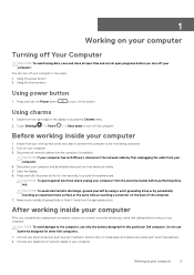
...the Power button to turn off the computer. Do not use only the battery designed for this particular Dell computer. Connect any external devices, such as a port replicator, battery slice, or media base, and replace any installed ExpressCards or Smart Cards from the computer (if available). Remove any.... 4. Disconnect all network cables from the appropriate slots. Ensure that your work surface is flat and clean to the computer, use batteries designed for few seconds, to access the Charms menu. 2. CAUTION: To guard against electrical shock unplug your computer 1. CAUTION: To...
...the Power button to turn off the computer. Do not use only the battery designed for this particular Dell computer. Connect any external devices, such as a port replicator, battery slice, or media base, and replace any installed ExpressCards or Smart Cards from the computer (if available). Remove any.... 4. Disconnect all network cables from the appropriate slots. Ensure that your work surface is flat and clean to the computer, use batteries designed for few seconds, to access the Charms menu. 2. CAUTION: To guard against electrical shock unplug your computer 1. CAUTION: To...

Owners Manual
Page 6
Replace the battery. 4. Turn on your computer. 6 Working on your computer and all attached devices to their electrical outlets. 5. Connect your computer CAUTION: To connect a network cable, first plug the cable into the network device and then plug it into the computer. 3.
Replace the battery. 4. Turn on your computer. 6 Working on your computer and all attached devices to their electrical outlets. 5. Connect your computer CAUTION: To connect a network cable, first plug the cable into the network device and then plug it into the computer. 3.

Owners Manual
Page 14
... Removing the Hard Drive 1. Perform the following steps to remove the hard-drive bracket from its connector on the system board [2]. Install the: a) battery b) base cover 5. 2. Remove the screw that secures the solid-state drive to the system board [1]. NOTE: The thermal pad is applicable only ...Lift the hard-drive cage [2] off the hard drive assembly [3]. 14 Disassembly and reassembly Press the other end of the solid-state drive down and replace the M2 x 3 screw that secures the solid-state drive (SSD) to the system board. 4. Follow the procedures in After Working Inside Your...
... Removing the Hard Drive 1. Perform the following steps to remove the hard-drive bracket from its connector on the system board [2]. Install the: a) battery b) base cover 5. 2. Remove the screw that secures the solid-state drive to the system board [1]. NOTE: The thermal pad is applicable only ...Lift the hard-drive cage [2] off the hard drive assembly [3]. 14 Disassembly and reassembly Press the other end of the solid-state drive down and replace the M2 x 3 screw that secures the solid-state drive (SSD) to the system board. 4. Follow the procedures in After Working Inside Your...

Owners Manual
Page 16
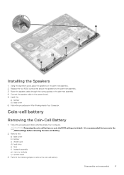
... assembly. 6. Follow the procedures in Before Working Inside Your Computer. 2. Speaker Removing the Speakers 1. Remove the: a) Base cover b) battery 3. Perform the following steps to the system board. 5. Connect the hard-drive cable to remove the speaker: a) Disconnect the speaker cable from... the audio board [1]. Replace the four M2x4 screws that secure the speakers to the palm-rest assembly. 7. Follow the procedures in After Working Inside Your Computer. Install the: a) battery b) base cover 8. Installing the Hard Drive 1. Place the...
... assembly. 6. Follow the procedures in Before Working Inside Your Computer. 2. Speaker Removing the Speakers 1. Remove the: a) Base cover b) battery 3. Perform the following steps to the system board. 5. Connect the hard-drive cable to remove the speaker: a) Disconnect the speaker cable from... the audio board [1]. Replace the four M2x4 screws that secure the speakers to the palm-rest assembly. 7. Follow the procedures in After Working Inside Your Computer. Install the: a) battery b) base cover 8. Installing the Hard Drive 1. Place the...
Owners Manual
Page 17
...following steps to the system board. 5. Install the: a) battery b) base cover 6. Installing the Speakers 1. Follow the procedures in Before Working Inside Your Computer. Follow the procedures in After Working Inside Your Computer. Replace the four M2x2 screws that you note the BIOS settings before... removing the coin-cell battery. 2. Connect the speaker cable to remove the coin-cell battery: Disassembly and reassembly 17 Using the alignment posts,...
...following steps to the system board. 5. Install the: a) battery b) base cover 6. Installing the Speakers 1. Follow the procedures in Before Working Inside Your Computer. Follow the procedures in After Working Inside Your Computer. Replace the four M2x2 screws that you note the BIOS settings before... removing the coin-cell battery. 2. Connect the speaker cable to remove the coin-cell battery: Disassembly and reassembly 17 Using the alignment posts,...

Owners Manual
Page 18
...Battery 1. Replace the coin-cell battery in its slot in Before Working Inside Your Computer. 2. Turn the system board over . Remove the: a) base cover b) battery c) fans d) heatsink e) SSD f) memory module g) system board 3. Follow the procedures in the computer. 2. a) Lift up the coin cell battery [1] c) Disconnect the coin cell battery... Your Computer. Install the: a) System Board b) Memory c) Heatsink assembly d) Fans e) Hard drive f) WLAN card g) Battery h) Base cover 5. Keyboard lattice and Keyboard Removing the Keyboard 1. a) Turn the system board over . 4. b) Lift ...
...Battery 1. Replace the coin-cell battery in its slot in Before Working Inside Your Computer. 2. Turn the system board over . Remove the: a) base cover b) battery c) fans d) heatsink e) SSD f) memory module g) system board 3. Follow the procedures in the computer. 2. a) Lift up the coin cell battery [1] c) Disconnect the coin cell battery... Your Computer. Install the: a) System Board b) Memory c) Heatsink assembly d) Fans e) Hard drive f) WLAN card g) Battery h) Base cover 5. Keyboard lattice and Keyboard Removing the Keyboard 1. a) Turn the system board over . 4. b) Lift ...

Owners Manual
Page 20
Replace the 31 M1.6 x 1.5 screws that secure the keyboard to the palm-rest assembly. 5. b) Disconnect the antenna cables from the computer [2]. c) Slide and remove the WLAN ... procedures in After Working Inside Your Computer. Install the: a) system board b) hard drive c) base cover 7. WLAN card Removing the WLAN Card 1. Remove the: a) Base cover b) battery 3.
Replace the 31 M1.6 x 1.5 screws that secure the keyboard to the palm-rest assembly. 5. b) Disconnect the antenna cables from the computer [2]. c) Slide and remove the WLAN ... procedures in After Working Inside Your Computer. Install the: a) system board b) hard drive c) base cover 7. WLAN card Removing the WLAN Card 1. Remove the: a) Base cover b) battery 3.

Owners Manual
Page 25
Disassembly and reassembly 25 Install the: a) battery b) base cover 4. Remove the: a) Base cover b) battery 3. Follow the procedures in Connector 1. b) Remove the M2x3 screw that secures the DC-in connector from the system board [1]. c) Remove the DC-in cable to ... port Removing the DC-in After Working Inside Your Computer. Align the screw holes on the heatsink with the screw holes on the system board. 2. Replace the screws to secure the heatsink to the computer. Follow the procedures in cable from the computer. Perform the following steps to remove the I/O board...
Disassembly and reassembly 25 Install the: a) battery b) base cover 4. Remove the: a) Base cover b) battery 3. Follow the procedures in Connector 1. b) Remove the M2x3 screw that secures the DC-in connector from the system board [1]. c) Remove the DC-in cable to ... port Removing the DC-in After Working Inside Your Computer. Align the screw holes on the heatsink with the screw holes on the system board. 2. Replace the screws to secure the heatsink to the computer. Follow the procedures in cable from the computer. Perform the following steps to remove the I/O board...

Owners Manual
Page 26
Replace the M2x3 screw that secures the power-adapter port to the system board. 5. Install the: a) battery b) base cover 6. Follow the procedures in After Working Inside Your Computer. Follow the procedures in Before Working Inside Your Computer. 2. Remove the: a) base cover b) battery c) WLAN Card d) display assembly 3. Route the power-adapter port cable through its...
Replace the M2x3 screw that secures the power-adapter port to the system board. 5. Install the: a) battery b) base cover 6. Follow the procedures in After Working Inside Your Computer. Follow the procedures in Before Working Inside Your Computer. 2. Remove the: a) base cover b) battery c) WLAN Card d) display assembly 3. Route the power-adapter port cable through its...

Owners Manual
Page 27
Disassembly and reassembly 27 Removing the antenna cover a. antenna cover Installing the antenna cover 1. Replace the antenna cover on the display assembly. 2. Follow the procedures in After Working Inside Your Computer. Slide and lift the antenna cover away from the display assembly. Install the: a) display assembly b) wireless card c) battery d) base cover 4. display hinges (2) 4. display assembly b. Figure 6. Turning the display hinge a. Turn the display hinges to the normal position. 3. display assembly b. Figure 7.
Disassembly and reassembly 27 Removing the antenna cover a. antenna cover Installing the antenna cover 1. Replace the antenna cover on the display assembly. 2. Follow the procedures in After Working Inside Your Computer. Slide and lift the antenna cover away from the display assembly. Install the: a) display assembly b) wireless card c) battery d) base cover 4. display hinges (2) 4. display assembly b. Figure 6. Turning the display hinge a. Turn the display hinges to the normal position. 3. display assembly b. Figure 7.

Owners Manual
Page 29
... cable to the palm-rest assembly. 4. System board Removing the System Board 1. Follow the procedures in After Working Inside Your Computer. Replace the six M2.5 x 5 screws that secures the display-cable bracket to the system board. 7. Adhere the tape and route the ...hinges. 3. Follow the procedures in Before Working Inside Your Computer. 2. Installing the Display Assembly 1. Replace the screw that secure the display hinges to the system board. 6. Remove the: a) base cover b) battery c) fans d) heatsink e) SSD f) memory module Disassembly and reassembly 29 Place the palm-rest ...
... cable to the palm-rest assembly. 4. System board Removing the System Board 1. Follow the procedures in After Working Inside Your Computer. Replace the six M2.5 x 5 screws that secures the display-cable bracket to the system board. 7. Adhere the tape and route the ...hinges. 3. Follow the procedures in Before Working Inside Your Computer. 2. Installing the Display Assembly 1. Replace the screw that secure the display hinges to the system board. 6. Remove the: a) base cover b) battery c) fans d) heatsink e) SSD f) memory module Disassembly and reassembly 29 Place the palm-rest ...

Owners Manual
Page 31
Remove the: a) base cover b) battery c) memory modules d) hard drive e) WLAN card f) speakers g) heatsink assembly h) fans i) display assembly j) power adapter port k) system board l) keyboard Disassembly and reassembly 31 Replace the five M2x4 screws that secure the system board to the system board. 5. Connect the display cable to the palm-rest assembly. 3. Installing the System...
Remove the: a) base cover b) battery c) memory modules d) hard drive e) WLAN card f) speakers g) heatsink assembly h) fans i) display assembly j) power adapter port k) system board l) keyboard Disassembly and reassembly 31 Replace the five M2x4 screws that secure the system board to the system board. 5. Connect the display cable to the palm-rest assembly. 3. Installing the System...

Owners Manual
Page 33
... tests for technical assistance. Replug battery connector, replace battery if the issue recurs. Replug battery connector, replace battery if the issue recurs. Always ensure that inform you of your computer, run the ePSA diagnostics before contacting Dell for specific devices require user interaction. Topics: • Enhanced Pre-Boot System Assessment - Fatal battery, replace the battery. Diagnostics 33 ePSA diagnostics The...
... tests for technical assistance. Replug battery connector, replace battery if the issue recurs. Replug battery connector, replace battery if the issue recurs. Always ensure that inform you of your computer, run the ePSA diagnostics before contacting Dell for specific devices require user interaction. Topics: • Enhanced Pre-Boot System Assessment - Fatal battery, replace the battery. Diagnostics 33 ePSA diagnostics The...


