
Owners Manual
Page 4
ePSA diagnostics 33 Device Status Lights...33 5 System Setup Options...35 6 Technical Specifications...39 7 Contacting Dell...44 4 Contents Installing the Heatsink...25 Power connector port...25 Removing the DC-in Connector...25 Installing the DC-in Adapter Port...26 Antenna cover...26 Removing the antenna cover...26 Installing the antenna cover...27 Display Assembly...
ePSA diagnostics 33 Device Status Lights...33 5 System Setup Options...35 6 Technical Specifications...39 7 Contacting Dell...44 4 Contents Installing the Heatsink...25 Power connector port...25 Removing the DC-in Connector...25 Installing the DC-in Adapter Port...26 Antenna cover...26 Removing the antenna cover...26 Installing the antenna cover...27 Display Assembly...
Owners Manual
Page 5
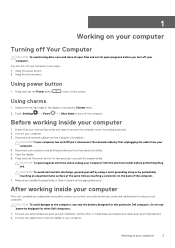
.... 6. Using the charms menu Using power button 1. Do not use only the battery designed for other Dell computers. 1. Before working inside your computer has an RJ45 port, disconnect the network cable by periodically touching an unpainted metal surface at the same time as an ExpressCard....cables from the appropriate slots. Remove any cards, such as touching a connector on your computer. Connect any external devices, such as a port replicator, battery slice, or media base, and replace any installed ExpressCards or Smart Cards from the computer (if available). CAUTION: If your...
.... 6. Using the charms menu Using power button 1. Do not use only the battery designed for other Dell computers. 1. Before working inside your computer has an RJ45 port, disconnect the network cable by periodically touching an unpainted metal surface at the same time as an ExpressCard....cables from the appropriate slots. Remove any cards, such as touching a connector on your computer. Connect any external devices, such as a port replicator, battery slice, or media base, and replace any installed ExpressCards or Smart Cards from the computer (if available). CAUTION: If your...

Owners Manual
Page 7
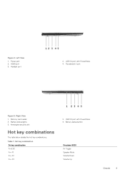
Back 1. speakers 7. WLAN card 11. heatsink Chassis 7 battery 8. Inside View - I /O board cable 9. system fan 4. video-card fan 12. Topics: • System Overview • Hot key combinations System Overview Figure 1. system board 5. 2 Chassis This chapter illustrates the multiple chassis views along with the ports and connectors and also explains the FN hot key combinations. memory modules 2. power connector 3. I /O board 10. hard drive 6.
Back 1. speakers 7. WLAN card 11. heatsink Chassis 7 battery 8. Inside View - I /O board cable 9. system fan 4. video-card fan 12. Topics: • System Overview • Hot key combinations System Overview Figure 1. system board 5. 2 Chassis This chapter illustrates the multiple chassis views along with the ports and connectors and also explains the FN hot key combinations. memory modules 2. power connector 3. I /O board 10. hard drive 6.
Owners Manual
Page 9
Memory card reader 3. Kensington security slot Hot key combinations The table below details the hot key combinations. Figure 4. Left View 1. HDMI port 5. Hot key combination Fn key combination Fn+ESC Fn+ F1 Fn+ F2 Fn+ F3 2. USB 3.0 port with PowerShare 4. Right View 1. Power port 3. Table 1. Battery status lights 5. USB 3.0 port with PowerShare 4. Headset port 2. Thunderbolt 3 port Figure 5. Battery status button Precision 5520 Fn Toggle Speaker Mute Volume Down Volume Up Chassis 9
Memory card reader 3. Kensington security slot Hot key combinations The table below details the hot key combinations. Figure 4. Left View 1. HDMI port 5. Hot key combination Fn key combination Fn+ESC Fn+ F1 Fn+ F2 Fn+ F3 2. USB 3.0 port with PowerShare 4. Right View 1. Power port 3. Table 1. Battery status lights 5. USB 3.0 port with PowerShare 4. Headset port 2. Thunderbolt 3 port Figure 5. Battery status button Precision 5520 Fn Toggle Speaker Mute Volume Down Volume Up Chassis 9

Owners Manual
Page 25
... the computer. Follow the procedures in Before Working Inside Your Computer. 2. Follow the procedures in After Working Inside Your Computer. Installing the Heatsink 1. Power connector port Removing the DC-in cable to the system board. 3. b) Remove the M2x3 screw that secures the DC-in Connector 1.
... the computer. Follow the procedures in Before Working Inside Your Computer. 2. Follow the procedures in After Working Inside Your Computer. Installing the Heatsink 1. Power connector port Removing the DC-in cable to the system board. 3. b) Remove the M2x3 screw that secures the DC-in Connector 1.

Owners Manual
Page 26
... through its routing guides on the palm-rest assembly. 2. Connect the power-adapter port cable to the palm-rest assembly. 4. Follow the procedures in Before Working Inside Your Computer. 2. Carefully turn the display hinges at an angle. 26 Disassembly ... c) WLAN Card d) display assembly 3. Follow the procedures in After Working Inside Your Computer. Replace the M2x3 screw that secures the power-adapter port to the system board. 5. Antenna cover Removing the antenna cover 1. Installing the DC-in adapter port into the slot on the palm-rest assembly. 3. Place the DC-in Adapter...
... through its routing guides on the palm-rest assembly. 2. Connect the power-adapter port cable to the palm-rest assembly. 4. Follow the procedures in Before Working Inside Your Computer. 2. Carefully turn the display hinges at an angle. 26 Disassembly ... c) WLAN Card d) display assembly 3. Follow the procedures in After Working Inside Your Computer. Replace the M2x3 screw that secures the power-adapter port to the system board. 5. Antenna cover Removing the antenna cover 1. Installing the DC-in adapter port into the slot on the palm-rest assembly. 3. Place the DC-in Adapter...

Owners Manual
Page 31
Connect the power-adapter port cable, speaker cable, keyboard-control board cable, touch-pad cable, and touch-screen cable to the system board. 5. Connect the display cable to the system .... 2. Palm rest Removing the Palmrest Assembly 1. Remove the: a) base cover b) battery c) memory modules d) hard drive e) WLAN card f) speakers g) heatsink assembly h) fans i) display assembly j) power adapter port k) system board l) keyboard Disassembly and reassembly 31 Follow the procedures in Before Working Inside Your Computer. 2. Installing the System Board 1. Replace the five M2x4 screws...
Connect the power-adapter port cable, speaker cable, keyboard-control board cable, touch-pad cable, and touch-screen cable to the system board. 5. Connect the display cable to the system .... 2. Palm rest Removing the Palmrest Assembly 1. Remove the: a) base cover b) battery c) memory modules d) hard drive e) WLAN card f) speakers g) heatsink assembly h) fans i) display assembly j) power adapter port k) system board l) keyboard Disassembly and reassembly 31 Follow the procedures in Before Working Inside Your Computer. 2. Installing the System Board 1. Replace the five M2x4 screws...

Owners Manual
Page 32
Tighten the screws to secure the display hinges to close the display. 4. Install the: a) keyboard b) system board c) power connector port d) display assembly e) fans f) heatsink assembly g) speakers h) WLAN card i) hard drive(optional) j) memory modules k) battery l) base cover 5. After performing the above steps, we are left with ...
Tighten the screws to secure the display hinges to close the display. 4. Install the: a) keyboard b) system board c) power connector port d) display assembly e) fans f) heatsink assembly g) speakers h) WLAN card i) hard drive(optional) j) memory modules k) battery l) base cover 5. After performing the above steps, we are left with ...
Owners Manual
Page 36
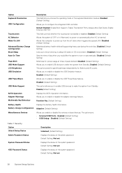
...set Displays the status of day when you would like the system to enable or disable the USB Emulation feature. Always Allow Dell Docks; Disabled (Default Setting) Minimizes AC power usage at times of the admin password. Security Option Unlock Setup Status Admin ... Default Setting: Not set Displays the status of the keyboard illumination feature. Default Enabled: Enable Boot Support, Enable Thunderbolt Ports; Enable External USB Port This field controls whether the touchscreen is inserted. Disabled (Default Setting) Maximizes battery health while still supporting heavy use during...
...set Displays the status of day when you would like the system to enable or disable the USB Emulation feature. Always Allow Dell Docks; Disabled (Default Setting) Minimizes AC power usage at times of the admin password. Security Option Unlock Setup Status Admin ... Default Setting: Not set Displays the status of the keyboard illumination feature. Default Enabled: Enable Boot Support, Enable Thunderbolt Ports; Enable External USB Port This field controls whether the touchscreen is inserted. Disabled (Default Setting) Maximizes battery health while still supporting heavy use during...

Owners Manual
Page 40
...Up to 4 GB GDDR5 Shared system memory Specification dual-channel High-Definition audio Specification Ethernet via USB-to-Ethernet Dongle (Optional). Ports and Connectors Feature Audio USB 3.0 Video Memory card reader Table 17. Display Feature Type Size Dimensions: Height Width Diagonal Active area...Specifications Specification • Intel HD Graphics 630/P630 with 7th Generation processors • Intel HD Graphics 530 with PowerShare • One Thunderbolt 3 port (USB-C) • one HDMI 1.4 SD 4.0 Specification 1920 x 1080 FHD 3840 x 2160 UltraHD Touch 100% Adobe Color gamut minimum 15...
...Up to 4 GB GDDR5 Shared system memory Specification dual-channel High-Definition audio Specification Ethernet via USB-to-Ethernet Dongle (Optional). Ports and Connectors Feature Audio USB 3.0 Video Memory card reader Table 17. Display Feature Type Size Dimensions: Height Width Diagonal Active area...Specifications Specification • Intel HD Graphics 630/P630 with 7th Generation processors • Intel HD Graphics 530 with PowerShare • One Thunderbolt 3 port (USB-C) • one HDMI 1.4 SD 4.0 Specification 1920 x 1080 FHD 3840 x 2160 UltraHD Touch 100% Adobe Color gamut minimum 15...

Quick Start Guide - Windows 7
Page 2
...; 15. 扬声器 16. 麦克风 17 18. 麦克风 19. 扬声器 20 1 2. HDMI ポート 11. Features 1. USB 3.0 port with PowerShare 6. Power status light 18. Power button 2. Kensington 3 4 5. 具备 PowerShare 功能的 USB 3.0 端口 6 7. 触摸板 8 9. PowerShare USB 3.0 12 13...
...; 15. 扬声器 16. 麦克风 17 18. 麦克风 19. 扬声器 20 1 2. HDMI ポート 11. Features 1. USB 3.0 port with PowerShare 6. Power status light 18. Power button 2. Kensington 3 4 5. 具备 PowerShare 功能的 USB 3.0 端口 6 7. 触摸板 8 9. PowerShare USB 3.0 12 13...


