Handling swollen Lithium-ion batteries
Page 1
... respective owners. Document Number: A05 Rev. or its subsidiaries. To discharge the battery, unplug the AC adapter from Dell. 1 Dell, EMC, and other computers with newer ultra-thin laptops) and long battery life. Do not use lithium-ion batteries. Lithium-ion polymer batteries have increased in popularity in recent years and have become standard in an...
... respective owners. Document Number: A05 Rev. or its subsidiaries. To discharge the battery, unplug the AC adapter from Dell. 1 Dell, EMC, and other computers with newer ultra-thin laptops) and long battery life. Do not use lithium-ion batteries. Lithium-ion polymer batteries have increased in popularity in recent years and have become standard in an...

Handling swollen Lithium-ion batteries
Page 2
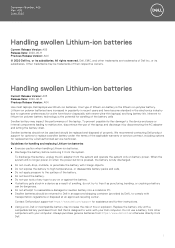
For more information on how to improve the performance and lifespan of the laptop battery and to minimize the possibility of occurrence of charge cycles, or exposure to high heat. Lithium-ion batteries can swell for various reasons such as age, number of the issue, see Dell Laptop Battery - Frequently Asked Questions. 2
For more information on how to improve the performance and lifespan of the laptop battery and to minimize the possibility of occurrence of charge cycles, or exposure to high heat. Lithium-ion batteries can swell for various reasons such as age, number of the issue, see Dell Laptop Battery - Frequently Asked Questions. 2

Ownerss Manual
Page 3
... computer...8 2 Removing and installing components 9 Base cover...9 Removing the base cover...9 Installing the base cover...10 Battery...10 Removing the battery...10 Installing the battery...11 Speaker...12 Removing the speaker...12 Installing the speaker...13 Hard drive...13 Removing the hard drive...13 Installing... the hard drive...14 Coin-cell battery...15 Removing the coin cell battery...15 Installing the coin cell battery...15 Solid State Drive ...16 Removing the M.2 Solid-State Drive - Windows...7 Before working inside ...
... computer...8 2 Removing and installing components 9 Base cover...9 Removing the base cover...9 Installing the base cover...10 Battery...10 Removing the battery...10 Installing the battery...11 Speaker...12 Removing the speaker...12 Installing the speaker...13 Hard drive...13 Removing the hard drive...13 Installing... the hard drive...14 Coin-cell battery...15 Removing the coin cell battery...15 Installing the coin cell battery...15 Solid State Drive ...16 Removing the M.2 Solid-State Drive - Windows...7 Before working inside ...

Ownerss Manual
Page 5
... specification...51 Ports and connectors specification...51 Display specification...51 Keyboard...52 Touchpad specification...52 Camera...52 Storage specification...52 Battery specification...52 AC adapter...53 Physical specification...53 Environmental specification...54 5 System setup...55 Boot menu...55 Navigation keys......in Windows ...65 Updating BIOS on systems with BitLocker enabled 66 Updating your system BIOS using a USB flash drive 66 Updating the Dell BIOS in Linux and Ubuntu environments 67 Flashing the BIOS from the F12 One-Time boot menu 67 System and setup password...70 ...
... specification...51 Ports and connectors specification...51 Display specification...51 Keyboard...52 Touchpad specification...52 Camera...52 Storage specification...52 Battery specification...52 AC adapter...53 Physical specification...53 Environmental specification...54 5 System setup...55 Boot menu...55 Navigation keys......in Windows ...65 Updating BIOS on systems with BitLocker enabled 66 Updating your system BIOS using a USB flash drive 66 Updating the Dell BIOS in Linux and Ubuntu environments 67 Flashing the BIOS from the F12 One-Time boot menu 67 System and setup password...70 ...

Ownerss Manual
Page 6
ePSA Diagnostic 3.0 76 Running the ePSA Diagnostics...76 Diagnostic LED...76 Battery status lights...77 8 Contacting Dell...78 6 Contents 7 Troubleshooting...76 Dell Enhanced Pre-Boot System Assessment -
ePSA Diagnostic 3.0 76 Running the ePSA Diagnostics...76 Diagnostic LED...76 Battery status lights...77 8 Contacting Dell...78 6 Contents 7 Troubleshooting...76 Dell Enhanced Pre-Boot System Assessment -

Ownerss Manual
Page 8
... computer and all network cables from being scratched. 2. Turn on your work surface is connected to the computer, use batteries designed for this particular Dell computer. Connect any replacement procedure, ensure that your computer. 8 Working on the back of the computer. 8. Do ...not use only the battery designed for other Dell computers. 1. Disconnect all attached devices from the electrical outlet before turning on your computer has an RJ45 port, disconnect...
... computer and all network cables from being scratched. 2. Turn on your work surface is connected to the computer, use batteries designed for this particular Dell computer. Connect any replacement procedure, ensure that your computer. 8 Working on the back of the computer. 8. Do ...not use only the battery designed for other Dell computers. 1. Disconnect all attached devices from the electrical outlet before turning on your computer has an RJ45 port, disconnect...

Ownerss Manual
Page 10
... eight M2.5 x 6 screws to secure the base cover to the computer. 5. Follow the procedure in Before working inside your computer. Battery Removing the battery 1. To remove the battery: a) Disconnect the battery cable [1] from the battery [3]. 10 Removing and installing components Press the edges of the cover until it clicks into place. 3. c) Peel the hard disk...
... eight M2.5 x 6 screws to secure the base cover to the computer. 5. Follow the procedure in Before working inside your computer. Battery Removing the battery 1. To remove the battery: a) Disconnect the battery cable [1] from the battery [3]. 10 Removing and installing components Press the edges of the cover until it clicks into place. 3. c) Peel the hard disk...

Ownerss Manual
Page 11
Connect the battery cable to the connector on the computer. 2. Installing the battery 1. e) Lift the battery away from the system [2]. Insert the battery into the slot on the system board. d) Remove the four M2.0 x 3 screws [1]. Removing and installing components 11
Connect the battery cable to the connector on the computer. 2. Installing the battery 1. e) Lift the battery away from the system [2]. Insert the battery into the slot on the system board. d) Remove the four M2.0 x 3 screws [1]. Removing and installing components 11

Ownerss Manual
Page 12
... the connector on the system board and close the latch. 4. Remove the: a) base cover b) battery 3. Lift the speakers, along with the speaker cable, and remove it away from routing channel [2]. 4. Follow the procedure in After working inside your computer. 2. Follow ...
... the connector on the system board and close the latch. 4. Remove the: a) base cover b) battery 3. Lift the speakers, along with the speaker cable, and remove it away from routing channel [2]. 4. Follow the procedure in After working inside your computer. 2. Follow ...

Ownerss Manual
Page 13
... 13 b) Pry the hard drive cable to the system board. 4. Install the: a) battery b) base cover 5. Follow the procedure in After working inside your computer. 2. Remove the: a) base cover b) battery 3. Hard drive Removing the hard drive 1. To disconnect the cable: a) Lift the latch..., and disconnect the hard drive cable from the battery [2]. Align the speakers along the slots on the system. 3. Connect ...
... 13 b) Pry the hard drive cable to the system board. 4. Install the: a) battery b) base cover 5. Follow the procedure in After working inside your computer. 2. Remove the: a) base cover b) battery 3. Hard drive Removing the hard drive 1. To disconnect the cable: a) Lift the latch..., and disconnect the hard drive cable from the battery [2]. Align the speakers along the slots on the system. 3. Connect ...

Ownerss Manual
Page 15
... connector on the system board. 2. Installing the coin cell battery 1. Connect the coin cell battery cable to release from the adhesive and lift it away from the connector on the system board [1]. Coin-cell battery Removing the coin cell battery 1. Follow the procedure in After working inside your computer. ...2. Affix the hard drive cable on the system board. 3. Install the: a) battery b) base cover 6. Follow the procedure in After working inside your computer. Removing and installing components 15 Remove the base cover. 3. ...
... connector on the system board. 2. Installing the coin cell battery 1. Connect the coin cell battery cable to release from the adhesive and lift it away from the connector on the system board [1]. Coin-cell battery Removing the coin cell battery 1. Follow the procedure in After working inside your computer. ...2. Affix the hard drive cable on the system board. 3. Install the: a) battery b) base cover 6. Follow the procedure in After working inside your computer. Removing and installing components 15 Remove the base cover. 3. ...

Ownerss Manual
Page 26
Connect the power cable to its slot in the fingerprint board. 4. System board Removing the system board 1. Remove the: a) base cover b) battery c) system fan d) heat sink e) solid-state drive(SSD) 26 Removing and installing components Close the display hinge and secure it with the two M2.5 x 4 screws ...
Connect the power cable to its slot in the fingerprint board. 4. System board Removing the system board 1. Remove the: a) base cover b) battery c) system fan d) heat sink e) solid-state drive(SSD) 26 Removing and installing components Close the display hinge and secure it with the two M2.5 x 4 screws ...

Ownerss Manual
Page 29
... cable and speaker cable to the system and lift the touchpad away from the connector in Before working inside your computer. Remove the: a) base cover b) battery c) hard drive 3. To remove the touchpad: a) Remove the four M2.0 x 2 screws that secure the touchpad support bracket to the connector in After working inside your... [1]. Follow the procedure in the system board. 5. Removing and installing components 29 Touchpad Removing touchpad 1. Install the: a) solid state drive(SSD) b) heat sink c) system fan d) battery e) base cover 7.
... cable and speaker cable to the system and lift the touchpad away from the connector in Before working inside your computer. Remove the: a) base cover b) battery c) hard drive 3. To remove the touchpad: a) Remove the four M2.0 x 2 screws that secure the touchpad support bracket to the connector in After working inside your... [1]. Follow the procedure in the system board. 5. Removing and installing components 29 Touchpad Removing touchpad 1. Install the: a) solid state drive(SSD) b) heat sink c) system fan d) battery e) base cover 7.

Ownerss Manual
Page 30
... and lift the display assembly. 30 Removing and installing components Replace the four screws to secure the touchpad to the system. 2. Install the: a) hard drive b) battery c) base cover 5. Display assembly Removing display assembly 1. b) Remove the five M2.5 x 6 screws [2] that secure the hinge bracket to the connector in the system board [1]. Installing...
... and lift the display assembly. 30 Removing and installing components Replace the four screws to secure the touchpad to the system. 2. Install the: a) hard drive b) battery c) base cover 5. Display assembly Removing display assembly 1. b) Remove the five M2.5 x 6 screws [2] that secure the hinge bracket to the connector in the system board [1]. Installing...

Ownerss Manual
Page 39
Follow the procedure in Before working inside your computer. Follow the procedure in After working inside your computer. 2. Remove the: a) base cover b) battery c) system fan d) heat sink e) solid state drive(SSD) f) WLAN card g) Input output(I/O) board h) power button i) hard drive j) system board k) display assembly 3. b) Disconnect the keyboard cable ...
Follow the procedure in Before working inside your computer. Follow the procedure in After working inside your computer. 2. Remove the: a) base cover b) battery c) system fan d) heat sink e) solid state drive(SSD) f) WLAN card g) Input output(I/O) board h) power button i) hard drive j) system board k) display assembly 3. b) Disconnect the keyboard cable ...

Ownerss Manual
Page 41
... d) touchpad e) system fan f) heat sink g) solid state drive(SSD) h) WLAN card i) Input output(I /O) board f) WLAN card g) solid state drive(SSD) h) heat sink i) system fan j) battery k) base cover 6. b) system board c) hard drive d) powered button e) Input Output(I /O) board j) power button k) hard drive l) system board m) keyboard n) display assembly NOTE: After the removal of ...
... d) touchpad e) system fan f) heat sink g) solid state drive(SSD) h) WLAN card i) Input output(I /O) board f) WLAN card g) solid state drive(SSD) h) heat sink i) system fan j) battery k) base cover 6. b) system board c) hard drive d) powered button e) Input Output(I /O) board j) power button k) hard drive l) system board m) keyboard n) display assembly NOTE: After the removal of ...

Ownerss Manual
Page 42
... rest: a) display assembly b) keyboard c) system board d) hard drive e) powered button f) Input Output(I/O) board g) WLAN card h) solid state drive(SSD) i) heat sink j) system fan k) touchpad l) speaker m) battery n) base cover 4.
... rest: a) display assembly b) keyboard c) system board d) hard drive e) powered button f) Input Output(I/O) board g) WLAN card h) solid state drive(SSD) i) heat sink j) system fan k) touchpad l) speaker m) battery n) base cover 4.

Ownerss Manual
Page 48
.... NOTE: The HDMI 1.4 will rival the Digital Cinema systems used in tuner to send audio data "upstream" to take full advantage of all those portable battery packs you used in digital photography and computer graphics • 4K Support - USB Type-C USB Type-C is an industry-supported, uncompressed, all-digital audio/video...
.... NOTE: The HDMI 1.4 will rival the Digital Cinema systems used in tuner to send audio data "upstream" to take full advantage of all those portable battery packs you used in digital photography and computer graphics • 4K Support - USB Type-C USB Type-C is an industry-supported, uncompressed, all-digital audio/video...

Ownerss Manual
Page 52
... - 5400 RPM • 1 TB - 5400 RPM • 128 GB M.2 SSD • 256 GB M.2 SSD • 512 GB M.2 SSD • HDD Free Fall Sensor (FFS) Support Battery specification Feature Wattage Type Length Height Specification 42 Whr (3 Cell) Lithium-ion/polymer Li-ion/polymer 175.36 mm (6.90 inch) 5.9 mm (0.23 inch) 52...
... - 5400 RPM • 1 TB - 5400 RPM • 128 GB M.2 SSD • 256 GB M.2 SSD • 512 GB M.2 SSD • HDD Free Fall Sensor (FFS) Support Battery specification Feature Wattage Type Length Height Specification 42 Whr (3 Cell) Lithium-ion/polymer Li-ion/polymer 175.36 mm (6.90 inch) 5.9 mm (0.23 inch) 52...

Ownerss Manual
Page 53
...° F) Non-Operating -20° C to 60° C (4° F to 140° F) Typical Amp-hour 3.684Ahr capacity Typical Watt-hour 42 Whr capacity Coin-cell battery 3 V CR2032 lithium ion cell AC adapter Feature Wattage Input voltage Input current (maximum) Input frequency Output current (continuous) Rated output voltage Height Width Depth Weight...
...° F) Non-Operating -20° C to 60° C (4° F to 140° F) Typical Amp-hour 3.684Ahr capacity Typical Watt-hour 42 Whr capacity Coin-cell battery 3 V CR2032 lithium ion cell AC adapter Feature Wattage Input voltage Input current (maximum) Input frequency Output current (continuous) Rated output voltage Height Width Depth Weight...


