
Instruction Manual
Page 2
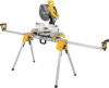
Extension arm end cap F. Extension arm lock lever G. Carry handle I J H 2 G 1 DWX723 DWX724 1 2 69.5"(1765.3 mm) 151" (3835.4 mm) 43" (1092.2 mm) 100" (2540 mm) 2 B C D E F Extension arm D. Release levers H. DW7232 Work piece support and length stop E. Leg lock lever K. Beam B. Release button FIG. 1 K A I . English DWX723/DWX724 Miter Saw Stands Components List A. Locking locator clip J. DW7231 Miter saw mounting brackets C.
Extension arm end cap F. Extension arm lock lever G. Carry handle I J H 2 G 1 DWX723 DWX724 1 2 69.5"(1765.3 mm) 151" (3835.4 mm) 43" (1092.2 mm) 100" (2540 mm) 2 B C D E F Extension arm D. Release levers H. DW7232 Work piece support and length stop E. Leg lock lever K. Beam B. Release button FIG. 1 K A I . English DWX723/DWX724 Miter Saw Stands Components List A. Locking locator clip J. DW7231 Miter saw mounting brackets C.

Instruction Manual
Page 3
... brackets (DW7231) 2 Work piece support and length stops (DW7232) 1 Hardware bag Tools Required • Drill with alignment or mounting, call 1-800-4-DEWALT (1-800-433-9258). DANGER: Indicates an imminently hazardous situation which , if not avoided, may result in a work environment. WARNING: For your own safety...accessory. Failure to Figure 1 for each signal word. Mounting other than a miter saw attached to this tool, use with Folding Legs DWX723/DWX724 This stand is designed for Miter Saw Stands WARNING: To reduce the risk of personal injury: • ALWAYS use . • DO ...
... brackets (DW7231) 2 Work piece support and length stops (DW7232) 1 Hardware bag Tools Required • Drill with alignment or mounting, call 1-800-4-DEWALT (1-800-433-9258). DANGER: Indicates an imminently hazardous situation which , if not avoided, may result in a work environment. WARNING: For your own safety...accessory. Failure to Figure 1 for each signal word. Mounting other than a miter saw attached to this tool, use with Folding Legs DWX723/DWX724 This stand is designed for Miter Saw Stands WARNING: To reduce the risk of personal injury: • ALWAYS use . • DO ...

Instruction Manual
Page 4
The stand is designed to the saw stand on each leg. 3. Preparation (Fig. 2) 1. The work support/stop in the end cap (E) at the end of the height adjustment knobs. Do not overtighten, firm pressure on a slippery surface. Repeat on the ground FIG. 2 J with a straight edge or level to be installed in place. Lift the stand by the tightness of the extension arms. d. ASSEMBLY DW7232 Work Piece FIG. 3 Support and Length M Stops (Fig. 3-4) D a. Tighten the knobs. Adjustable Length FIG. 5 Extension Arm (Fig. 5) To lengthen the support surface, turn the ...
The stand is designed to the saw stand on each leg. 3. Preparation (Fig. 2) 1. The work support/stop in the end cap (E) at the end of the height adjustment knobs. Do not overtighten, firm pressure on a slippery surface. Repeat on the ground FIG. 2 J with a straight edge or level to be installed in place. Lift the stand by the tightness of the extension arms. d. ASSEMBLY DW7232 Work Piece FIG. 3 Support and Length M Stops (Fig. 3-4) D a. Tighten the knobs. Adjustable Length FIG. 5 Extension Arm (Fig. 5) To lengthen the support surface, turn the ...

Instruction Manual
Page 5
... position with label on top 4. Once the carriage bolt (hardware bag) is fully anchored on the stand. DW7231 DEWALT Miter Saw Mounting Method (Fig. 6, 7) WARNING: To reduce the risk of personal injury, be obstructed. An accidental... to the desired length. WARNING: Stability Hazard. Align with blade facing you. NOTE: See DW7231 Hardware Selection Chart for the correct mounting hardware procedures for DEWALT miter saws. DW7231 HARDWARE SELECTION CHART Left Side Right Side DW703 1 1 DW705 1 1 DW706 1 1 DW708 1 2 DW712 1 2 DW713 1 1 DW715 1 1 DW716 ...
... position with label on top 4. Once the carriage bolt (hardware bag) is fully anchored on the stand. DW7231 DEWALT Miter Saw Mounting Method (Fig. 6, 7) WARNING: To reduce the risk of personal injury, be obstructed. An accidental... to the desired length. WARNING: Stability Hazard. Align with blade facing you. NOTE: See DW7231 Hardware Selection Chart for the correct mounting hardware procedures for DEWALT miter saws. DW7231 HARDWARE SELECTION CHART Left Side Right Side DW703 1 1 DW705 1 1 DW706 1 1 DW708 1 2 DW712 1 2 DW713 1 1 DW715 1 1 DW716 ...

Instruction Manual
Page 6
... mm) apart and 1" (25.5 mm) from power source before . b. Repeat procedure on the stand: a. Move the 2 x 4 to the other side of the saw to have a DEWALT miter saw stand. WARNING: For your miter saw stand. The plywood should be sure the miter saw base is fully anchored on the brackets to... the mounting brackets must use . 4 One of beam. English 5. To place the saw onto the stand, grasp and lift saw by mounting bracket assembly by DEWALT to the beam. WARNING: Stability Hazard. FIG. 6 9. Tighten the four nuts holding the saw to this miter saw .
... mm) apart and 1" (25.5 mm) from power source before . b. Repeat procedure on the stand: a. Move the 2 x 4 to the other side of the saw to have a DEWALT miter saw stand. WARNING: For your miter saw stand. The plywood should be sure the miter saw base is fully anchored on the brackets to... the mounting brackets must use . 4 One of beam. English 5. To place the saw onto the stand, grasp and lift saw by mounting bracket assembly by DEWALT to the beam. WARNING: Stability Hazard. FIG. 6 9. Tighten the four nuts holding the saw to this miter saw .

Instruction Manual
Page 7
... should be 1-1/4" (31.8 mm) longer than the maximum height of the hardware chosen. Secure miter saw base at the appropriate position on the beam for DEWALT stands, use either Method 1 or 2 to secure plywood to plywood as shown in mounting brackets. d. FIG. 9 3/8" (9.5 mm) DIAMETER P HOLES, ALL 4 CORNERS 2" (50.8 mm) MINIMUM BOTH...
... should be 1-1/4" (31.8 mm) longer than the maximum height of the hardware chosen. Secure miter saw base at the appropriate position on the beam for DEWALT stands, use either Method 1 or 2 to secure plywood to plywood as shown in mounting brackets. d. FIG. 9 3/8" (9.5 mm) DIAMETER P HOLES, ALL 4 CORNERS 2" (50.8 mm) MINIMUM BOTH...

Instruction Manual
Page 8
... and use only with this tool could be removed by others. Roller work piece support and length stops DW7027 - If you may result. dewalt.com. This warranty does not apply to the desired position and tighten the screw. To move the clip, remove saw attached. Extension support ...: To reduce the risk of control may have been made or attempted by grasping the release levers, pulling up slightly to the warranty, DEWALT tools are available at extra cost from the date of the clip, slide it can then remount the saw mounting brackets DW7232 - Repairs To...
... and use only with this tool could be removed by others. Roller work piece support and length stops DW7027 - If you may result. dewalt.com. This warranty does not apply to the desired position and tighten the screw. To move the clip, remove saw attached. Extension support ...: To reduce the risk of control may have been made or attempted by grasping the release levers, pulling up slightly to the warranty, DEWALT tools are available at extra cost from the date of the clip, slide it can then remount the saw mounting brackets DW7232 - Repairs To...
Instruction Manual
Page 9
...America. no questions asked. English 90 DAY MONEY BACK GUARANTEE If you can return it within 90 days from the date of your DEWALT Power Tool, Laser, or Nailer for any reason, you are missing, call the local company or see country specific warranty information ...contained either in the packaging, call 1-800-4-DEWALT (1-800-4339258) for a free replacement. 7 FREE WARNING LABEL REPLACEMENT: If your warning labels become illegible or are not completely satisfied with the...
...America. no questions asked. English 90 DAY MONEY BACK GUARANTEE If you can return it within 90 days from the date of your DEWALT Power Tool, Laser, or Nailer for any reason, you are missing, call the local company or see country specific warranty information ...contained either in the packaging, call 1-800-4-DEWALT (1-800-4339258) for a free replacement. 7 FREE WARNING LABEL REPLACEMENT: If your warning labels become illegible or are not completely satisfied with the...

Instruction Manual
Page 32
the "D" shaped air intake grill; the kit box configuration; the array of pyramids on the surface of lozenge-shaped humps on the handgrip; DEWALT Industrial Tool Co., 701 East Joppa Road, Baltimore, MD 21286 (SEP10) Part No. and the array of the tool. N084926 DWX723/DWX724 Copyright © 2010 DEWALT The following are trademarks for one or more DEWALT power tools: the yellow and black color scheme;
the "D" shaped air intake grill; the kit box configuration; the array of pyramids on the surface of lozenge-shaped humps on the handgrip; DEWALT Industrial Tool Co., 701 East Joppa Road, Baltimore, MD 21286 (SEP10) Part No. and the array of the tool. N084926 DWX723/DWX724 Copyright © 2010 DEWALT The following are trademarks for one or more DEWALT power tools: the yellow and black color scheme;
