

User Manual
Page 10
...EVGA nForce® 780i SLI motherboard. As a rule, for the microprocessor ‰ System memory support: Supports dual channel DDR2 533/667/800, and up to 8 GBs DDR2 memory. ‰ Graphics Card This motherboard supports 3-way SLI with three x16 PCI Express slots. ‰ Power Supply The power supply requirement is dependent upon the power...install. Parts NOT in an SLI configuration, you will need a minimum of a 1000 W power supply. Supports up to install each of a 500 W power supply. These instructions tell you how to 1200 MHz SLI-Ready Memory. nForce 780i SLI Motherboard Before...
...EVGA nForce® 780i SLI motherboard. As a rule, for the microprocessor ‰ System memory support: Supports dual channel DDR2 533/667/800, and up to 8 GBs DDR2 memory. ‰ Graphics Card This motherboard supports 3-way SLI with three x16 PCI Express slots. ‰ Power Supply The power supply requirement is dependent upon the power...install. Parts NOT in an SLI configuration, you will need a minimum of a 1000 W power supply. Supports up to install each of a 500 W power supply. These instructions tell you how to 1200 MHz SLI-Ready Memory. nForce 780i SLI Motherboard Before...

User Manual
Page 25
... support 3-way SLI, this motherboard has the following specific power supply requirements: ‰ Minimum 1000 W peak power ‰ Six PCI-E power connectors configured in the following configurations (see Figure 3): ¾ Four 6-pin (3x2) and two 8-pin (4x2) PCI-E power connectors or ¾ Six 6-pin (3x2) PCI-E power connectors EVGA 14 8-pin (4x2) PCT-E Connector 6-pin (3x2) PCI... 2.0 Adapter ‰ Expansion slots ‰ CMOS jumper settings See Figure 1 on page 7 to locate the connectors and jumpers referenced in either of the following procedure. Power Supply Connectors
... support 3-way SLI, this motherboard has the following specific power supply requirements: ‰ Minimum 1000 W peak power ‰ Six PCI-E power connectors configured in the following configurations (see Figure 3): ¾ Four 6-pin (3x2) and two 8-pin (4x2) PCI-E power connectors or ¾ Six 6-pin (3x2) PCI-E power connectors EVGA 14 8-pin (4x2) PCT-E Connector 6-pin (3x2) PCI... 2.0 Adapter ‰ Expansion slots ‰ CMOS jumper settings See Figure 1 on page 7 to locate the connectors and jumpers referenced in either of the following procedure. Power Supply Connectors

User Manual
Page 26
...make sure it is the main power supply connector located along the edge of the board next to the DIMM slots. To determine what you will be installing. Make sure that the power supply cable and pins are for your specific configuration or a certified power supply vendor, refer to www.slizone....com. 24-pin ATX Power (PWR1) PWR1 is secure. PWR1 Motherboard Connector PWR1 Pin Assignments Connector 24 ...
...make sure it is the main power supply connector located along the edge of the board next to the DIMM slots. To determine what you will be installing. Make sure that the power supply cable and pins are for your specific configuration or a certified power supply vendor, refer to www.slizone....com. 24-pin ATX Power (PWR1) PWR1 is secure. PWR1 Motherboard Connector PWR1 Pin Assignments Connector 24 ...

User Manual
Page 30
... power LED PWRSW RESET cable to these two pins of the case to these two pins. When the system is in S1, + S3, S4, S5 status, the LED is off rather than using the power supply ...button. ‰ HD_LED Attach the hard disk drive indicator LED cable to these two pins. Pressing the power button on the front panel turns the system on and off...the RESET switch is on the connectors to the corresponding pins. ‰ PWRSW Attach the power button cable from the front panel of the connector. Be sure to these two pins. The...
... power LED PWRSW RESET cable to these two pins of the case to these two pins. When the system is in S1, + S3, S4, S5 status, the LED is off rather than using the power supply ...button. ‰ HD_LED Attach the hard disk drive indicator LED cable to these two pins. Pressing the power button on the front panel turns the system on and off...the RESET switch is on the connectors to the corresponding pins. ‰ PWRSW Attach the power button cable from the front panel of the connector. Be sure to these two pins. The...
User Manual
Page 38
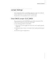
... on the motherboard shows a ∆ next to pin 1. Clear CMOS Jumper: CLR_CMOS The motherboard uses the CMOS RAM to clear CMOS: 1. Turn off the AC power supply and connect pins 1 and 2 together using the jumper cap. 2. Use the following procedure to store all board configurations to normal (pins 2 and 3 together with the...
... on the motherboard shows a ∆ next to pin 1. Clear CMOS Jumper: CLR_CMOS The motherboard uses the CMOS RAM to clear CMOS: 1. Turn off the AC power supply and connect pins 1 and 2 together using the jumper cap. 2. Use the following procedure to store all board configurations to normal (pins 2 and 3 together with the...

User Manual
Page 125
780i 3-Way SLI Motherboard Power Management Setup menu, 58 power supply requirement, ix Power-on by alarm function, 59 power-on function, 60 Primary Master/Slave PIO, 55 Primary Master/Slave UDMA, 55 PWR1 connector, 13 PWR1 pin assignments, 13 PWR2 connector, 14 PWRLED, 17 PWRSW, 17 Quick Power On Self Test, ...75 removable device startup priority, 37 RESET, 17 Reset switch cable, 17 Row Address Strobe, 74 Row Cycle Time, 75 safety instructions, 7 EVGA 114 SATA Signal Cable, 4 SATA Spread Spectrum, 43 Scalable Link Interface, 97 Security Options, 39 Serial ATA II connector, 16 Serial-ATA ...
780i 3-Way SLI Motherboard Power Management Setup menu, 58 power supply requirement, ix Power-on by alarm function, 59 power-on function, 60 Primary Master/Slave PIO, 55 Primary Master/Slave UDMA, 55 PWR1 connector, 13 PWR1 pin assignments, 13 PWR2 connector, 14 PWRLED, 17 PWRSW, 17 Quick Power On Self Test, ...75 removable device startup priority, 37 RESET, 17 Reset switch cable, 17 Row Address Strobe, 74 Row Cycle Time, 75 safety instructions, 7 EVGA 114 SATA Signal Cable, 4 SATA Spread Spectrum, 43 Scalable Link Interface, 97 Security Options, 39 Serial ATA II connector, 16 Serial-ATA ...
