User Guide
Page 3
Introduction Equipment ...7 EVGA nForce 680i LT SLI Motherboard 8 Hardware Installation 11 Safety Instructions 11 Preparing the Motherboard 12 Installing the CPU 12 Installing the CPU Fan 13 Installing Memory DIMMs 13 Installing the Motherboard 14 Installing the I/O Shield 14 Securing the Motherboard into the Chassis 14 Connecting Cables and Setting Switches 15 Power Connections 16 24-pin ATX Power (PWR1 16 8-pin...
Introduction Equipment ...7 EVGA nForce 680i LT SLI Motherboard 8 Hardware Installation 11 Safety Instructions 11 Preparing the Motherboard 12 Installing the CPU 12 Installing the CPU Fan 13 Installing Memory DIMMs 13 Installing the Motherboard 14 Installing the I/O Shield 14 Securing the Motherboard into the Chassis 14 Connecting Cables and Setting Switches 15 Power Connections 16 24-pin ATX Power (PWR1 16 8-pin...

User Guide
Page 7
... ‰ Cooling fan for your specific configuration, go through the installation instructions, we are assuming you are going to install and connect your new EVGA nForce® 680i LT SLI motherboard. See Installing Graphics Cards in an SLI Configuration on page 65. ‰ Power Supply The power supply requirement is a PCI Express card. These instructions tell you how...
... ‰ Cooling fan for your specific configuration, go through the installation instructions, we are assuming you are going to install and connect your new EVGA nForce® 680i LT SLI motherboard. See Installing Graphics Cards in an SLI Configuration on page 65. ‰ Power Supply The power supply requirement is a PCI Express card. These instructions tell you how...
User Guide
Page 8
Intentions of the Kit This kit provides you with the motherboard and all connecting cables necessary to reinstall an operating system even though the current drives have an operating system. viii When replacing a motherboard in a PC cabinet, you will need many of the cables provided in the kit. If you are replacing a motherboard, you will not need to install the motherboard into a PC cabinet. If however, you are building a PC, you will use most of the cables.
Intentions of the Kit This kit provides you with the motherboard and all connecting cables necessary to reinstall an operating system even though the current drives have an operating system. viii When replacing a motherboard in a PC cabinet, you will need many of the cables provided in the kit. If you are replacing a motherboard, you will not need to install the motherboard into a PC cabinet. If however, you are building a PC, you will use most of the cables.

User Guide
Page 12
NVIDIA FirstPacket™ Technology Be the 'King of Ping' with NVIDIA nForce NVIDIA networking delivers the highest network throughput at the lowest CPU utilization. High Definition Audio (HDA) High definition audio brings consumer electronics quality sound to -use connectivity for eight channels, supporting new audio formats. Using HDA, systems can deliver 192 kHz...
NVIDIA FirstPacket™ Technology Be the 'King of Ping' with NVIDIA nForce NVIDIA networking delivers the highest network throughput at the lowest CPU utilization. High Definition Audio (HDA) High definition audio brings consumer electronics quality sound to -use connectivity for eight channels, supporting new audio formats. Using HDA, systems can deliver 192 kHz...

User Guide
Page 16
EVGA nForce 680i LT SLI Motherboard The EVGA nForce 680i LT SLI motherboard with the NVIDIA nForce 680i LT SLI SPP and MCP processors is a PCI Express, SLI-ready motherboard. SATA Signal Cable (Qty Six) Used to support the Serial ATA protocol and each one connects a single drive to the motherboard Comm2 Bracket Cable IDE-ATA 133 HDD Cable SLI Connector Used to either the front or back panels of the chassis...
EVGA nForce 680i LT SLI Motherboard The EVGA nForce 680i LT SLI motherboard with the NVIDIA nForce 680i LT SLI SPP and MCP processors is a PCI Express, SLI-ready motherboard. SATA Signal Cable (Qty Six) Used to support the Serial ATA protocol and each one connects a single drive to the motherboard Comm2 Bracket Cable IDE-ATA 133 HDD Cable SLI Connector Used to either the front or back panels of the chassis...
User Guide
Page 19
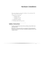
...; Installing the CPU ¾ Installing the CPU fan ¾ Installing the memory ‰ Installing the motherboard ‰ Connecting cables and setting switches Safety Instructions To reduce the risk of the motherboard. Remember to remove power from your computer by disconnecting the AC main source before removing or installing any equipment from/to the...
...; Installing the CPU ¾ Installing the CPU fan ¾ Installing the memory ‰ Installing the motherboard ‰ Connecting cables and setting switches Safety Instructions To reduce the risk of the motherboard. Remember to remove power from your computer by disconnecting the AC main source before removing or installing any equipment from/to the...

User Guide
Page 22
...studs or spacers to allow the mother board to be easier to make all the connections. If the I /O shield into place and for the chassis covers to install the I /O shield. 4. Secure the motherboard with a minimum of the chassis. Use the following procedure to lock into place ...and make all the connections prior to this step or to secure the motherboard and then make sure it fits securely. Installing the I/O Shield The motherboard kit comes with the chassis vents according to block radio frequency transmissions, ...
...studs or spacers to allow the mother board to be easier to make all the connections. If the I /O shield into place and for the chassis covers to install the I /O shield. 4. Secure the motherboard with a minimum of the chassis. Use the following procedure to lock into place ...and make all the connections prior to this step or to secure the motherboard and then make sure it fits securely. Installing the I/O Shield The motherboard kit comes with the chassis vents according to block radio frequency transmissions, ...
User Guide
Page 23
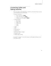
... switch settings necessary on page 9 to locate the connectors and jumpers referenced in the following procedure. 15 This will include: ‰ Power Connections ¾ 24-pin ATX power (PWR1) ¾ 8-pin ATX 12V power (PWR2) ¾ Auxiliary power for graphics (PWR3) ‰ Internal Headers ¾ Front panel ¾ ... ‰ IDE ‰ Serial ATA II ‰ Chassis Fans ‰ Rear panel USB 2.0 Adapter ‰ Expansion slots ‰ CMOS jumper settings See Figure 1 on the motherboard.
... switch settings necessary on page 9 to locate the connectors and jumpers referenced in the following procedure. 15 This will include: ‰ Power Connections ¾ 24-pin ATX power (PWR1) ¾ 8-pin ATX 12V power (PWR2) ¾ Auxiliary power for graphics (PWR3) ‰ Internal Headers ¾ Front panel ¾ ... ‰ IDE ‰ Serial ATA II ‰ Chassis Fans ‰ Rear panel USB 2.0 Adapter ‰ Expansion slots ‰ CMOS jumper settings See Figure 1 on the motherboard.
User Guide
Page 24
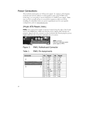
Power Connections This motherboard requires an ATX power supply. To determine what you power requirements are for your specific configuration, refer to the DIMM slots. To support a PCI Express motherboard with the connector on the motherboard. Firmly plug the power supply cable into the connector and make sure it ... going to need a minimum of the board next to www.slizone.com. 24-pin ATX Power (PWR1) PWR1 is secure. PWR1 Motherboard Connector Table 1. Card edge PWR1 connector Plug power cable from system power supply to cover all the expansion cards you are properly aligned...
Power Connections This motherboard requires an ATX power supply. To determine what you power requirements are for your specific configuration, refer to the DIMM slots. To support a PCI Express motherboard with the connector on the motherboard. Firmly plug the power supply cable into the connector and make sure it ... going to need a minimum of the board next to www.slizone.com. 24-pin ATX Power (PWR1) PWR1 is secure. PWR1 Motherboard Connector Table 1. Card edge PWR1 connector Plug power cable from system power supply to cover all the expansion cards you are properly aligned...
User Guide
Page 25
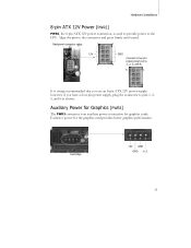
... Auxiliary Power for Graphics (PWR3) The PWR3 connector is an auxiliary power connection for the graphics card provides better graphics performance. Exclusive power for graphics cards. Backpanel connector edge. 5 1 12V 8 GND Connect a four-pin power plug to the connector and press firmly until seated. ...however, if you use an 8-pin ATX 12V power supply; Hardware Installation 8-pin ATX 12V Power (PWR2) PWR2, the 8-pin ATX 12V power connection, is used to provide power to ...
... Auxiliary Power for Graphics (PWR3) The PWR3 connector is an auxiliary power connection for the graphics card provides better graphics performance. Exclusive power for graphics cards. Backpanel connector edge. 5 1 12V 8 GND Connect a four-pin power plug to the connector and press firmly until seated. ...however, if you use an 8-pin ATX 12V power supply; Hardware Installation 8-pin ATX 12V Power (PWR2) PWR2, the 8-pin ATX 12V power connection, is used to provide power to ...
User Guide
Page 26
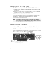
...Serial ATA II interface allows up to the hard disk documentation for primary storage devices. GND GND GND TX+ RX+ TX- Connect the gray connector to the motherboard connector. These connectors support the thin Serial ATA II cables for the jumper settings. If you install two hard disk drives,...drives may be reduced to the Ultra ATA master device. 3. Connecting Serial ATA Cables The Serial ATA II connector is used to connect the Serial ATA II device to the drive. Connect the end without the lock to the motherboard. Connect the blue connector (the cable end with the two closely spaced...
...Serial ATA II interface allows up to the hard disk documentation for primary storage devices. GND GND GND TX+ RX+ TX- Connect the gray connector to the motherboard connector. These connectors support the thin Serial ATA II cables for the jumper settings. If you install two hard disk drives,...drives may be reduced to the Ultra ATA master device. 3. Connecting Serial ATA Cables The Serial ATA II connector is used to connect the Serial ATA II device to the drive. Connect the end without the lock to the motherboard. Connect the blue connector (the cable end with the two closely spaced...
User Guide
Page 27
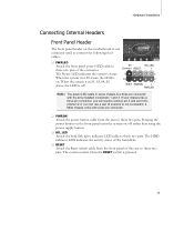
...PWRSW Attach the power button cable from the front panel of scissors to cut out position 2. The Power LED indicates the system's status. No HD_LED Connect RESET - + 9 1 10 2 1 Blank PWRSW - + PWRLED Note: The power LED cable in S1, S3, S4, S5 status, the LED is one...‰ PWRLED Attach the front panel power LED cable to these two pins of the connector. Hardware Installation Connecting Internal Headers Front Panel Header The front panel header on this motherboard is off rather than using the power supply button. ‰ HD_LED Attach the hard disk drive indicator LED...
...PWRSW Attach the power button cable from the front panel of scissors to cut out position 2. The Power LED indicates the system's status. No HD_LED Connect RESET - + 9 1 10 2 1 Blank PWRSW - + PWRLED Note: The power LED cable in S1, S3, S4, S5 status, the LED is one...‰ PWRLED Attach the front panel power LED cable to these two pins of the connector. Hardware Installation Connecting Internal Headers Front Panel Header The front panel header on this motherboard is off rather than using the power supply button. ‰ HD_LED Attach the hard disk drive indicator LED...
User Guide
Page 28
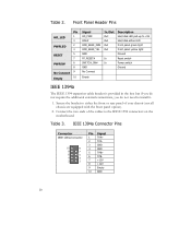
... with the front panel option). 2. Front Panel Header Pins Pin HD_LED 1 3 PWRLED 2 4 RESET 5 7 PWRSW 6 8 No Connect 9 Empty 10 Signal HD_PWR HDA# HDR_BLNK_GRN HDR_BLNK_YEL GND FP_RESET# SWITCH_ON# GND No Connect In/Out Out Out Out Out In In Description Hard disk LED pull-up to +5V Hard disk active...IEEE 1394 expansion cable bracket is provided in the box but if you do not require the additional external connections, you do not need to the IEEE 1394 connectors on the motherboard. Secure the bracket to either the front or rear panel of the cables to install it. 1. IEEE...
... with the front panel option). 2. Front Panel Header Pins Pin HD_LED 1 3 PWRLED 2 4 RESET 5 7 PWRSW 6 8 No Connect 9 Empty 10 Signal HD_PWR HDA# HDR_BLNK_GRN HDR_BLNK_YEL GND FP_RESET# SWITCH_ON# GND No Connect In/Out Out Out Out Out In In Description Hard disk LED pull-up to +5V Hard disk active...IEEE 1394 expansion cable bracket is provided in the box but if you do not require the additional external connections, you do not need to the IEEE 1394 connectors on the motherboard. Secure the bracket to either the front or rear panel of the cables to install it. 1. IEEE...
User Guide
Page 29
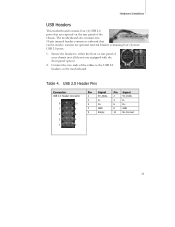
... that are equipped with the front panel option). 2. Connect the two ends of the cables to the USB 2.0 headers on the rear panel of your chassis (not all chassis are exposed on the motherboard. Table 4. Secure the bracket to either the front ...or rear panel of the chassis. Hardware Installation USB Headers This motherboard contains four (4) USB 2.0 ports that can be used to connect an optional external bracket containing four (4) more USB 2.0 ports. 1. USB 2.0 Header Pins Connector USB 2.0 Header Connector 9 10 7 8 5 6 3 4 1...
... that are equipped with the front panel option). 2. Connect the two ends of the cables to the USB 2.0 headers on the rear panel of your chassis (not all chassis are exposed on the motherboard. Table 4. Secure the bracket to either the front ...or rear panel of the chassis. Hardware Installation USB Headers This motherboard contains four (4) USB 2.0 ports that can be used to connect an optional external bracket containing four (4) more USB 2.0 ports. 1. USB 2.0 Header Pins Connector USB 2.0 Header Connector 9 10 7 8 5 6 3 4 1...

User Guide
Page 31
...nForce 680i LT SLI SPP and MCP have active fans to help to pins 1, 2, and 3 on the motherboard connector. 4 3 21 GND SENSE PWR CONTROL 23 GND +12V SENSE CPU Fan Connector Note that the CPU fan cable can be either a 3-pin or a 4-pin connector. Connect a 3-pin connector to cool the chips. Hardware Installation Fan Connections... in the PC Health Status section of the CMOS Setup. Both fans are two fan connections, the system fan and the CPU fan. nForce 680i LT SLI SPP fan connector. nForce 680i LT SLI MCP fan connector. The fans plug into a 3 2 1 3-pin connector.
...nForce 680i LT SLI SPP and MCP have active fans to help to pins 1, 2, and 3 on the motherboard connector. 4 3 21 GND SENSE PWR CONTROL 23 GND +12V SENSE CPU Fan Connector Note that the CPU fan cable can be either a 3-pin or a 4-pin connector. Connect a 3-pin connector to cool the chips. Hardware Installation Fan Connections... in the PC Health Status section of the CMOS Setup. Both fans are two fan connections, the system fan and the CPU fan. nForce 680i LT SLI SPP fan connector. nForce 680i LT SLI MCP fan connector. The fans plug into a 3 2 1 3-pin connector.
User Guide
Page 32
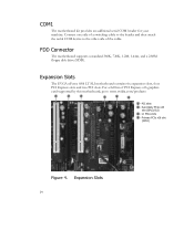
... EVGA nForce 680i LT SLI motherboard contains six expansion slots, four PCI Express slots and two PCI slots. Secondary PCIe x16 slot (GPU2/SLI) 3 - Primary PCIe x16 slot (GPU1) Figure 4. Expansion Slots 24 COM1 The motherboard kit provides an additional serial COM header for your machine. FDD Connector The motherboard... x16 graphics card supported by this motherboard, go to the other side of a switching cable to the header and then attach the serial COM device to www.nvidia.com/products 1 2 1 3 4 3 1 - x1 PCIe slots 4 - PCI slots 2 - Connect one side of the cable.
... EVGA nForce 680i LT SLI motherboard contains six expansion slots, four PCI Express slots and two PCI slots. Secondary PCIe x16 slot (GPU2/SLI) 3 - Primary PCIe x16 slot (GPU1) Figure 4. Expansion Slots 24 COM1 The motherboard kit provides an additional serial COM header for your machine. FDD Connector The motherboard... x16 graphics card supported by this motherboard, go to the other side of a switching cable to the header and then attach the serial COM device to www.nvidia.com/products 1 2 1 3 4 3 1 - x1 PCIe slots 4 - PCI slots 2 - Connect one side of the cable.

User Guide
Page 34
... following procedure to pin 1. Turn the AC power supply back on the motherboard shows a ∆ next to clear CMOS: 1. Turn off the AC power supply and connect pins 1 and 2 together using the jumper cap. 2. Clear CMOS Jumper: CLR_CMOS The motherboard uses the CMOS RAM to store all board configurations to normal (pins 2 and...
... following procedure to pin 1. Turn the AC power supply back on the motherboard shows a ∆ next to clear CMOS: 1. Turn off the AC power supply and connect pins 1 and 2 together using the jumper cap. 2. Clear CMOS Jumper: CLR_CMOS The motherboard uses the CMOS RAM to store all board configurations to normal (pins 2 and...
User Guide
Page 77
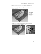
Connect the PCI Express supplementary power connectors from the system power supply to build your NVIDIA SLI-Ready PC system: 1. Two SLI graphics cards installed in an SLI Configuration Use the following procedure to each of the graphic cards: From Power Supply 69 Install two SLI-Ready graphic cards into the connectors. Installing Graphics Cards in the two (block) PCI Express slots on the motherboard (see Figure 29). Be sure to seat the graphic cards into the two black PCI Express x16 slots on the motherboard. 2.
Connect the PCI Express supplementary power connectors from the system power supply to build your NVIDIA SLI-Ready PC system: 1. Two SLI graphics cards installed in an SLI Configuration Use the following procedure to each of the graphic cards: From Power Supply 69 Install two SLI-Ready graphic cards into the connectors. Installing Graphics Cards in the two (block) PCI Express slots on the motherboard (see Figure 29). Be sure to seat the graphic cards into the two black PCI Express x16 slots on the motherboard. 2.