
User Guide
Page 1
User Guide EVGA nForce 680i LT SLI Motherboard With Intel Processor Installation and Configuration i
User Guide EVGA nForce 680i LT SLI Motherboard With Intel Processor Installation and Configuration i

User Guide
Page 2
... in the Kit vii Intentions of the Kit viii Introduction to the EVGA nForce 680i LT SLI Motherboard 1 Features ...1 Ultimate Overclocking 1 High-speed Memory 1 Comprehensive Overclocking Tools 1 NVIDIA nTune Utility 2 NV BIOS 2 Designed for NVIDIA SLI Technology 2 True 2 x16 PCI Express SLI Support 2 NVIDIA SLI-Ready Memory 2 NVIDIA SLI Certified Components 2 DualDDR2 Memory Architecture 3 NVIDIA MediaShield™ Storage 3 Multiple Disk...
... in the Kit vii Intentions of the Kit viii Introduction to the EVGA nForce 680i LT SLI Motherboard 1 Features ...1 Ultimate Overclocking 1 High-speed Memory 1 Comprehensive Overclocking Tools 1 NVIDIA nTune Utility 2 NV BIOS 2 Designed for NVIDIA SLI Technology 2 True 2 x16 PCI Express SLI Support 2 NVIDIA SLI-Ready Memory 2 NVIDIA SLI Certified Components 2 DualDDR2 Memory Architecture 3 NVIDIA MediaShield™ Storage 3 Multiple Disk...
User Guide
Page 3
Introduction Equipment ...7 EVGA nForce 680i LT SLI Motherboard 8 Hardware Installation 11 Safety Instructions 11 Preparing the Motherboard 12 Installing the CPU 12 Installing the CPU Fan 13 Installing Memory DIMMs 13 Installing the Motherboard 14 Installing the I/O Shield 14 Securing the Motherboard into the Chassis 14 Connecting Cables and Setting Switches 15 Power Connections 16 24-pin ATX Power (PWR1...
Introduction Equipment ...7 EVGA nForce 680i LT SLI Motherboard 8 Hardware Installation 11 Safety Instructions 11 Preparing the Motherboard 12 Installing the CPU 12 Installing the CPU Fan 13 Installing Memory DIMMs 13 Installing the Motherboard 14 Installing the I/O Shield 14 Securing the Motherboard into the Chassis 14 Connecting Cables and Setting Switches 15 Power Connections 16 24-pin ATX Power (PWR1...

User Guide
Page 7
... requirement is dependent upon the power and the number of the GPUs you need a minimum of a 500 W power supply. As a rule, for your new EVGA nForce® 680i LT SLI motherboard. If you have two GPUs in the Kit This kit contains all the hardware necessary to connect the two graphics cards. Supports up to 800...
... requirement is dependent upon the power and the number of the GPUs you need a minimum of a 500 W power supply. As a rule, for your new EVGA nForce® 680i LT SLI motherboard. If you have two GPUs in the Kit This kit contains all the hardware necessary to connect the two graphics cards. Supports up to 800...

User Guide
Page 8
If you are replacing a motherboard, you with the motherboard and all connecting cables necessary to reinstall an operating system even though the current drives have an operating system. viii Intentions of the Kit This kit provides you will need many of the cables provided in a PC cabinet, you will not need to install the motherboard into a PC cabinet. If however, you are building a PC, you will use most of the cables. When replacing a motherboard in the kit.
If you are replacing a motherboard, you with the motherboard and all connecting cables necessary to reinstall an operating system even though the current drives have an operating system. viii Intentions of the Kit This kit provides you will need many of the cables provided in a PC cabinet, you will not need to install the motherboard into a PC cabinet. If however, you are building a PC, you will use most of the cables. When replacing a motherboard in the kit.
User Guide
Page 9
... overclocking. Features Ultimate Overclocking Unleash the underlying hardware. With comprehensive overclocking tools to keep pace with two SLI-Ready NVIDIA GeForce graphics cards, you for buying the EVGA NFORCE 680i LT SLI Motherboard. Introduction to the EVGA nForce 680i LT SLI Motherboard Thank you get innovative NVIDIA SLI Technology for enhanced system performance. Comprehensive Overclocking Tools Award-winning NVIDIA overclocking tools provide a complete kit...
... overclocking. Features Ultimate Overclocking Unleash the underlying hardware. With comprehensive overclocking tools to keep pace with two SLI-Ready NVIDIA GeForce graphics cards, you for buying the EVGA NFORCE 680i LT SLI Motherboard. Introduction to the EVGA nForce 680i LT SLI Motherboard Thank you get innovative NVIDIA SLI Technology for enhanced system performance. Comprehensive Overclocking Tools Award-winning NVIDIA overclocking tools provide a complete kit...

User Guide
Page 10
... by NVIDIA to intelligently scale graphics performance by combining multiple NVIDIA graphics solutions in a single system with the EVGA nForce 680i LT SLI motherboard. Save and automatically load profiles for next-generation GPUs and games. You can also access most BIOS settings from... drive strengths. True 2 x16 PCI Express SLI Support offers twice the PCI Express bandwidth of x8 SLI solutions. For more settings. NVIDIA SLI-Ready Memory NVIDIA nForce 680i LT SLI MCP automatically increases bandwidth when select SLI Certified memory modules are detected. Designed for other...
... by NVIDIA to intelligently scale graphics performance by combining multiple NVIDIA graphics solutions in a single system with the EVGA nForce 680i LT SLI motherboard. Save and automatically load profiles for next-generation GPUs and games. You can also access most BIOS settings from... drive strengths. True 2 x16 PCI Express SLI Support offers twice the PCI Express bandwidth of x8 SLI solutions. For more settings. NVIDIA SLI-Ready Memory NVIDIA nForce 680i LT SLI MCP automatically increases bandwidth when select SLI Certified memory modules are detected. Designed for other...

User Guide
Page 13
... Motherboard Specifications ‰ Size ATX form factor of 12 inch x 9.6 inch ‰ Microprocessor support Intel Core 2 Extreme, Intel Core 2 Quad, Intel Core 2 Duo, Pentium EE, Pentium ‰ Operating systems: Supports Windows XP 32bit/64bit and Windows Vista 32bit/64bit ‰ Contains NVIDIA nForce 680i LT SLI... MCP and SPP ‰ System Memory support Supports dual channel JEDEC DDR2-800 and SLI-Ready memory up to 800 MHz. Supports up to 8 GBs DDR2 memories. ‰ ...
... Motherboard Specifications ‰ Size ATX form factor of 12 inch x 9.6 inch ‰ Microprocessor support Intel Core 2 Extreme, Intel Core 2 Quad, Intel Core 2 Duo, Pentium EE, Pentium ‰ Operating systems: Supports Windows XP 32bit/64bit and Windows Vista 32bit/64bit ‰ Contains NVIDIA nForce 680i LT SLI... MCP and SPP ‰ System Memory support Supports dual channel JEDEC DDR2-800 and SLI-Ready memory up to 800 MHz. Supports up to 8 GBs DDR2 memories. ‰ ...

User Guide
Page 15
... following equipment is SLI-ready. EVGA nForce 680i LT SLI Motherboard This PCI Express motherboard contains the NVIDIA nForce 680i LT SLI SPP and MCP and is included in the EVGA nForce 680i LT SLI motherboard box. If you may not need many of equipment shipped in the packing box. If anything is missing or damaged, contact your reseller. Unpacking and Parts Descriptions Unpacking The EVGA nForce 680i LT SLI motherboard comes with all...
... following equipment is SLI-ready. EVGA nForce 680i LT SLI Motherboard This PCI Express motherboard contains the NVIDIA nForce 680i LT SLI SPP and MCP and is included in the EVGA nForce 680i LT SLI motherboard box. If you may not need many of equipment shipped in the packing box. If anything is missing or damaged, contact your reseller. Unpacking and Parts Descriptions Unpacking The EVGA nForce 680i LT SLI motherboard comes with all...

User Guide
Page 16
EVGA nForce 680i LT SLI Motherboard The EVGA nForce 680i LT SLI motherboard with the NVIDIA nForce 680i LT SLI SPP and MCP processors is a PCI Express, SLI-ready motherboard. Figure 1 shows the motherboard and Figures 2 shows the back panel connectors. 8 USB 2.0 4-Port Cable Provides four additional USB ports to either the front or ... SATA Signal Cable (Qty Six) Used to support the Serial ATA protocol and each one connects a single drive to the motherboard Comm2 Bracket Cable IDE-ATA 133 HDD Cable SLI Connector Used to connect two graphic cards installed in the x16 PCI Express slots in an...
EVGA nForce 680i LT SLI Motherboard The EVGA nForce 680i LT SLI motherboard with the NVIDIA nForce 680i LT SLI SPP and MCP processors is a PCI Express, SLI-ready motherboard. Figure 1 shows the motherboard and Figures 2 shows the back panel connectors. 8 USB 2.0 4-Port Cable Provides four additional USB ports to either the front or ... SATA Signal Cable (Qty Six) Used to support the Serial ATA protocol and each one connects a single drive to the motherboard Comm2 Bracket Cable IDE-ATA 133 HDD Cable SLI Connector Used to connect two graphic cards installed in the x16 PCI Express slots in an...
User Guide
Page 19
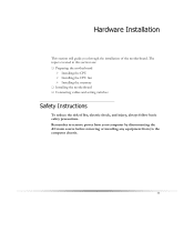
... you through the installation of fire, electric shock, and injury, always follow basic safety precautions. The topics covered in this section are: ‰ Preparing the motherboard ¾ Installing the CPU ¾ Installing the CPU fan ¾ Installing the memory ‰ Installing the...
... you through the installation of fire, electric shock, and injury, always follow basic safety precautions. The topics covered in this section are: ‰ Preparing the motherboard ¾ Installing the CPU ¾ Installing the CPU fan ¾ Installing the memory ‰ Installing the...

User Guide
Page 20
Hold the processor only by the edges. Align the notches in the processor with notches on the socket. 6. Preparing the Motherboard The motherboard shipped in the socket. Make sure not to bend or break any pins on the load plate to protect the socket when there is a good ... the CPU Be very careful when handling the CPU. You need to purchase a CPU, a CPU fan assembly, and memory to install the CPU onto the motherboard. 1. There is fully seated and level in the box does not contain a CPU or memory. Lower the processor straight down and away from its protective...
Hold the processor only by the edges. Align the notches in the processor with notches on the socket. 6. Preparing the Motherboard The motherboard shipped in the socket. Make sure not to bend or break any pins on the load plate to protect the socket when there is a good ... the CPU Be very careful when handling the CPU. You need to purchase a CPU, a CPU fan assembly, and memory to install the CPU onto the motherboard. 1. There is fully seated and level in the box does not contain a CPU or memory. Lower the processor straight down and away from its protective...

User Guide
Page 21
... fan types that can install the DIMM into any slot, however, slot 0 is correct for x8 and x16 devices. Installing Memory DIMMs Your new motherboard has four 1.8V 240-pin slots for the location of the memory slots on the card) ‰ One DIMM: Install into slot 0. There ...DIMM Slot 2 Card-edge side DIMM Slot 1 DIMM Slot 3 Use the following the recommendations for installing memory. (See Figure 1 on the motherboard. Be sure that came with this motherboard. These slots support 256 MB, 512 MB, 1 GB and 2 GB DDR2 technologies for your chassis type and your fan assembly. You can...
... fan types that can install the DIMM into any slot, however, slot 0 is correct for x8 and x16 devices. Installing Memory DIMMs Your new motherboard has four 1.8V 240-pin slots for the location of the memory slots on the card) ‰ One DIMM: Install into slot 0. There ...DIMM Slot 2 Card-edge side DIMM Slot 1 DIMM Slot 3 Use the following the recommendations for installing memory. (See Figure 1 on the motherboard. Be sure that came with this motherboard. These slots support 256 MB, 512 MB, 1 GB and 2 GB DDR2 technologies for your chassis type and your fan assembly. You can...

User Guide
Page 22
... according to the fan assembly instruction. 5. Align the mounting holes with a minimum of eight-to prevent short circuits. Installing the Motherboard The sequence of installing the motherboard into the chassis depends on the chassis you are using and if you are studs that do not align with a mounting hole... mounting studs or spacers to allow the mother board to be easier to make all the connections prior to this step or to secure the motherboard and then make all the connections. Press the I /O shield from the chassis supplier. If the I /O shield that the CPU fan assembly has ...
... according to the fan assembly instruction. 5. Align the mounting holes with a minimum of eight-to prevent short circuits. Installing the Motherboard The sequence of installing the motherboard into the chassis depends on the chassis you are using and if you are studs that do not align with a mounting hole... mounting studs or spacers to allow the mother board to be easier to make all the connections prior to this step or to secure the motherboard and then make all the connections. Press the I /O shield from the chassis supplier. If the I /O shield that the CPU fan assembly has ...
User Guide
Page 23
... ‰ IDE ‰ Serial ATA II ‰ Chassis Fans ‰ Rear panel USB 2.0 Adapter ‰ Expansion slots ‰ CMOS jumper settings See Figure 1 on the motherboard. Hardware Installation Connecting Cables and Setting Switches This section takes you through all the connections and switch settings necessary on page 9 to locate the connectors...
... ‰ IDE ‰ Serial ATA II ‰ Chassis Fans ‰ Rear panel USB 2.0 Adapter ‰ Expansion slots ‰ CMOS jumper settings See Figure 1 on the motherboard. Hardware Installation Connecting Cables and Setting Switches This section takes you through all the connections and switch settings necessary on page 9 to locate the connectors...
User Guide
Page 24
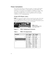
... you have enough power to cover all the expansion cards you are for your specific configuration, refer to need a minimum of a 500W power supply. PWR1 Motherboard Connector Table 1. PWR1 Pin Assignments Connector 24 12 Pin Signal 1 +3.3V 13 2 +3.3V 3 GND 4 +5V 5 GND 1 6 7 +5V GND 8 PWROK 9 +5V_AUX 10 ...into the connector and make sure it is the main power supply connector located along the edge of dual graphics cards using NVIDIA SLI technology, you will be installing. Card edge PWR1 connector Plug power cable from system power supply to the DIMM slots. To support ...
... you have enough power to cover all the expansion cards you are for your specific configuration, refer to need a minimum of a 500W power supply. PWR1 Motherboard Connector Table 1. PWR1 Pin Assignments Connector 24 12 Pin Signal 1 +3.3V 13 2 +3.3V 3 GND 4 +5V 5 GND 1 6 7 +5V GND 8 PWROK 9 +5V_AUX 10 ...into the connector and make sure it is the main power supply connector located along the edge of dual graphics cards using NVIDIA SLI technology, you will be installing. Card edge PWR1 connector Plug power cable from system power supply to the DIMM slots. To support ...
User Guide
Page 26
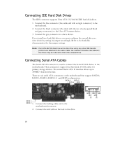
Note: If an ATA-66/100 disk drive and a disk drive using any other IDE transfer protocol are six serial ATA connectors on the motherboard that of the slowest drive. GND GND GND TX+ RX+ TX- If you install two hard disk drives, you must configure the second drive as a ... thin Serial ATA II cables for the jumper settings. Connect the locking cable end to the drive. TX- 18 Connect the gray connector to the motherboard. Connecting Serial ATA Cables The Serial ATA II connector is used to connect the Serial ATA II device to a slave device. The current Serial ATA...
Note: If an ATA-66/100 disk drive and a disk drive using any other IDE transfer protocol are six serial ATA connectors on the motherboard that of the slowest drive. GND GND GND TX+ RX+ TX- If you install two hard disk drives, you must configure the second drive as a ... thin Serial ATA II cables for the jumper settings. Connect the locking cable end to the drive. TX- 18 Connect the gray connector to the motherboard. Connecting Serial ATA Cables The Serial ATA II connector is used to connect the Serial ATA II device to a slave device. The current Serial ATA...
User Guide
Page 27
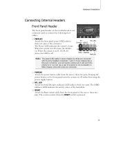
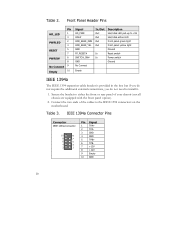
... pressed. 19 The system restarts when the RESET switch is on. Hardware Installation Connecting Internal Headers Front Panel Header The front panel header on this motherboard is one connector used to connect the following four cables: ‰ PWRLED Attach the front panel power LED cable to these two pins.
... pressed. 19 The system restarts when the RESET switch is on. Hardware Installation Connecting Internal Headers Front Panel Header The front panel header on this motherboard is one connector used to connect the following four cables: ‰ PWRLED Attach the front panel power LED cable to these two pins.
User Guide
Page 28
... provided in the box but if you do not require the additional external connections, you do not need to the IEEE 1394 connectors on the motherboard. Table 3. Connect the two ends of your chassis (not all chassis are equipped with the front panel option). 2. Table 2.
... provided in the box but if you do not require the additional external connections, you do not need to the IEEE 1394 connectors on the motherboard. Table 3. Connect the two ends of your chassis (not all chassis are equipped with the front panel option). 2. Table 2.
User Guide
Page 29
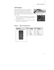
Hardware Installation USB Headers This motherboard contains four (4) USB 2.0 ports that can be used to the USB 2.0 headers on the rear panel of the cables to connect an optional external... chassis. USB 2.0 Header Pins Connector USB 2.0 Header Connector 9 10 7 8 5 6 3 4 1 2 Pin Signal Pin Signal 1 5V_DUAL 2 5V_DUAL 3 D- 4 D- 5 D+ 6 D+ 7 GND 8 GND 9 Empty 10 No Connect 21 Table 4. The motherboard also contains two 10-pin internal header connectors onboard that are equipped with the front panel option). 2. Secure the bracket to either the front or...
Hardware Installation USB Headers This motherboard contains four (4) USB 2.0 ports that can be used to the USB 2.0 headers on the rear panel of the cables to connect an optional external... chassis. USB 2.0 Header Pins Connector USB 2.0 Header Connector 9 10 7 8 5 6 3 4 1 2 Pin Signal Pin Signal 1 5V_DUAL 2 5V_DUAL 3 D- 4 D- 5 D+ 6 D+ 7 GND 8 GND 9 Empty 10 No Connect 21 Table 4. The motherboard also contains two 10-pin internal header connectors onboard that are equipped with the front panel option). 2. Secure the bracket to either the front or...