User Guide
Page 3
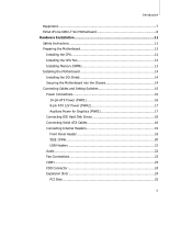
Introduction Equipment ...7 EVGA nForce 680i LT SLI Motherboard 8 Hardware Installation 11 Safety Instructions 11 Preparing the Motherboard 12 Installing the CPU 12 Installing the CPU Fan 13 Installing Memory DIMMs 13 Installing the Motherboard 14 Installing the I/O Shield 14 Securing the Motherboard into the Chassis 14 Connecting Cables and Setting Switches 15 Power Connections 16 24-pin ATX Power (PWR1 16 8-pin ATX 12V Power (PWR2...
Introduction Equipment ...7 EVGA nForce 680i LT SLI Motherboard 8 Hardware Installation 11 Safety Instructions 11 Preparing the Motherboard 12 Installing the CPU 12 Installing the CPU Fan 13 Installing Memory DIMMs 13 Installing the Motherboard 14 Installing the I/O Shield 14 Securing the Motherboard into the Chassis 14 Connecting Cables and Setting Switches 15 Power Connections 16 24-pin ATX Power (PWR1 16 8-pin ATX 12V Power (PWR2...
User Guide
Page 26
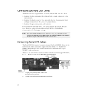
... end without the lock to 300MB/s data transfer rate. If you install two hard disk drives, you must configure the second drive as a slave device by setting its jumper accordingly. Connect the locking cable end to the motherboard. 2. Connect the blue connector (the cable end with the two ...Connect the black connector (the cable with a single connector) to the motherboard connector. Note: If an ATA-66/100 disk drive and a disk drive using any other IDE transfer protocol are six serial ATA connectors on the motherboard that of the slowest drive. There are attached to the same cable,...
... end without the lock to 300MB/s data transfer rate. If you install two hard disk drives, you must configure the second drive as a slave device by setting its jumper accordingly. Connect the locking cable end to the motherboard. 2. Connect the blue connector (the cable end with the two ...Connect the black connector (the cable with a single connector) to the motherboard connector. Note: If an ATA-66/100 disk drive and a disk drive using any other IDE transfer protocol are six serial ATA connectors on the motherboard that of the slowest drive. There are attached to the same cable,...
User Guide
Page 27
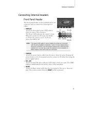
... position 2. The HDD indicator LED indicates the activity status of the hard disks. ‰ RESET Attach the Reset switch cable from the case to these two pins. Hardware Installation Connecting Internal Headers Front Panel Header The front panel header on this motherboard is one connector used to connect the following four cables: ‰...
... position 2. The HDD indicator LED indicates the activity status of the hard disks. ‰ RESET Attach the Reset switch cable from the case to these two pins. Hardware Installation Connecting Internal Headers Front Panel Header The front panel header on this motherboard is one connector used to connect the following four cables: ‰...
User Guide
Page 28
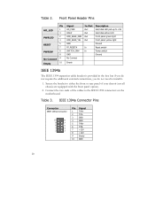
...5 4 3 2 1 Pin Signal 1 TPA+ 2 TPA- 3 GND 4 GND 5 TPB+ 6 TPB- 7 +12V 8 +12V 9 Empty 10 GND 20 Secure the bracket to the IEEE 1394 connectors on the motherboard. Connect the two ends of the cables to either the front or rear panel of your chassis (not all chassis are equipped with the front... Hard disk active LED Front panel green light Front panel yellow light Ground Reset switch Power switch Ground Empty IEEE 1394a The IEEE 1394 expansion cable bracket is provided in the box but if you do not require the additional external connections, you do not need to install it....
...5 4 3 2 1 Pin Signal 1 TPA+ 2 TPA- 3 GND 4 GND 5 TPB+ 6 TPB- 7 +12V 8 +12V 9 Empty 10 GND 20 Secure the bracket to the IEEE 1394 connectors on the motherboard. Connect the two ends of the cables to either the front or rear panel of your chassis (not all chassis are equipped with the front... Hard disk active LED Front panel green light Front panel yellow light Ground Reset switch Power switch Ground Empty IEEE 1394a The IEEE 1394 expansion cable bracket is provided in the box but if you do not require the additional external connections, you do not need to install it....