

User Guide
Page 3
... the Kit ...9 Motherboard ...10 Motherboard Specifications 10 Unpacking and Parts Descriptions 12 Unpacking ...12 Equipment ...12 EVGA X58 FTW3 Motherboard 14 Hardware Installation 17 Safety Instructions...17 Preparing the Motherboard 18 Installing the CPU...18 Installing the CPU Fan...19 Installing System Memory (DIMMs 20 Installing the Motherboard 21 Installing the I/O Shield 21 Securing the...
... the Kit ...9 Motherboard ...10 Motherboard Specifications 10 Unpacking and Parts Descriptions 12 Unpacking ...12 Equipment ...12 EVGA X58 FTW3 Motherboard 14 Hardware Installation 17 Safety Instructions...17 Preparing the Motherboard 18 Installing the CPU...18 Installing the CPU Fan...19 Installing System Memory (DIMMs 20 Installing the Motherboard 21 Installing the I/O Shield 21 Securing the...

User Guide
Page 6
EVGA X58 FTW3 Motherboard PCI/VGA Palette Snoop 55 INT Pin 1/2/3/4/5/6/7/8 Assignment 55 Maximum Payload Size 55 PC Health Status Menu ...56 SmartFan Function...57 Frequency/Voltage Control Menu 58 Memory Feature...59 Voltage Control...61 CPU Feature...63 Installing Drivers and Software 65 Windows XP/Vista/Win 7 Driver Installation 65 Appendix A. POST Codes 67 EVGA Glossary of Terms 74 Compliance Information 77 6
EVGA X58 FTW3 Motherboard PCI/VGA Palette Snoop 55 INT Pin 1/2/3/4/5/6/7/8 Assignment 55 Maximum Payload Size 55 PC Health Status Menu ...56 SmartFan Function...57 Frequency/Voltage Control Menu 58 Memory Feature...59 Voltage Control...61 CPU Feature...63 Installing Drivers and Software 65 Windows XP/Vista/Win 7 Driver Installation 65 Appendix A. POST Codes 67 EVGA Glossary of Terms 74 Compliance Information 77 6

User Guide
Page 7
... of Figures Figure 1. Figure 7. Figure 9. Figure 10. Figure 14. Figure 4. Figure 6. EVGA X58 FTW3 Motherboard Layout 14 Chassis Back Panel Connectors 16 PW1 Motherboard Connector 23 BIOS CMOS Setup Utility Main Menu 37 Standard CMOS Features Menu 39 Advanced ... Setup Menu 50 PnP/PCI Configuration Menu 53 PC Health Status Menu 56 Frequency/Voltage Control Menu 58 Memory Feature Menu 59 Voltage Control 61 CPU Feature Menu 63 7 Figure 5. Figure 8. Figure 13. Figure 12. Figure 2. Figure 3. Figure 11.
... of Figures Figure 1. Figure 7. Figure 9. Figure 10. Figure 14. Figure 4. Figure 6. EVGA X58 FTW3 Motherboard Layout 14 Chassis Back Panel Connectors 16 PW1 Motherboard Connector 23 BIOS CMOS Setup Utility Main Menu 37 Standard CMOS Features Menu 39 Advanced ... Setup Menu 50 PnP/PCI Configuration Menu 53 PC Health Status Menu 56 Frequency/Voltage Control Menu 58 Memory Feature Menu 59 Voltage Control 61 CPU Feature Menu 63 7 Figure 5. Figure 8. Figure 13. Figure 12. Figure 2. Figure 3. Figure 11.

User Guide
Page 17
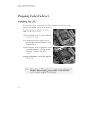
The topics covered in this section are: Preparing the motherboard Installing the CPU Installing the CPU fan Installing the memory Installing the motherboard Connecting cables Safety Instructions To reduce the risk of the motherboard. Remember to remove power from your computer by disconnecting the AC main source before removing or installing any equipment from/to the computer chassis. 17 EVGA FTW3 Motherboard Hardware Installation This section will guide you through the installation of fire, electric shock, and injury, always follow basic safety precautions.
The topics covered in this section are: Preparing the motherboard Installing the CPU Installing the CPU fan Installing the memory Installing the motherboard Connecting cables Safety Instructions To reduce the risk of the motherboard. Remember to remove power from your computer by disconnecting the AC main source before removing or installing any equipment from/to the computer chassis. 17 EVGA FTW3 Motherboard Hardware Installation This section will guide you through the installation of fire, electric shock, and injury, always follow basic safety precautions.
User Guide
Page 18
...you need to remove CPU for any reason you can replace the cover to install the CPU onto the motherboard: Unhook the socket lever by the edges and do not touch the bottom of the load plate and press down and away from the CPU Socket. EVGA X58 FTW3 Motherboard Preparing the ...Motherboard Installing the CPU Be very careful when handling the CPU. Remove the protective socket cover from the socket. Put your finger on the tail of the processor...
...you need to remove CPU for any reason you can replace the cover to install the CPU onto the motherboard: Unhook the socket lever by the edges and do not touch the bottom of the load plate and press down and away from the CPU Socket. EVGA X58 FTW3 Motherboard Preparing the ...Motherboard Installing the CPU Be very careful when handling the CPU. Remove the protective socket cover from the socket. Put your finger on the tail of the processor...

User Guide
Page 19
EVGA FTW3 Motherboard Align the notches in the socket. Be sure that the fan orientation is complete. Align notches with notches on the CPU Installing the CPU Fan There are many different fan types that came with out tilting or sliding it into the socket with you close and engage the socket... can be used with the notches on the socket. Close the load plate over the CPU and press down into the socket Note: Make sure the CPU is fully seated and level in the processor with this motherboard. The CPU installation is correct for your chassis type and your fan assembly. 19
EVGA FTW3 Motherboard Align the notches in the socket. Be sure that the fan orientation is complete. Align notches with notches on the CPU Installing the CPU Fan There are many different fan types that came with out tilting or sliding it into the socket with you close and engage the socket... can be used with the notches on the socket. Close the load plate over the CPU and press down into the socket Note: Make sure the CPU is fully seated and level in the processor with this motherboard. The CPU installation is correct for your chassis type and your fan assembly. 19

User Guide
Page 21
... to lock into the chassis, you are replacing an existing motherboard or working with an I/O shield that the CPU fan assembly has enough clearance for the expansion cards. This will depend on the covers. Press the I /O...make all the connections prior to this step or to secure the motherboard and then make sure the CPU Fan assembly is normally easier to block radio frequency transmissions, protects internal components from dust and foreign...on the system case being used to secure the motherboard first. EVGA FTW3 Motherboard Installing the Motherboard The sequence of the chassis.
... to lock into the chassis, you are replacing an existing motherboard or working with an I/O shield that the CPU fan assembly has enough clearance for the expansion cards. This will depend on the covers. Press the I /O...make all the connections prior to this step or to secure the motherboard and then make sure the CPU Fan assembly is normally easier to block radio frequency transmissions, protects internal components from dust and foreign...on the system case being used to secure the motherboard first. EVGA FTW3 Motherboard Installing the Motherboard The sequence of the chassis.
User Guide
Page 24
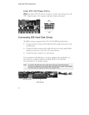
EVGA X58 FTW3 Motherboard 8-pin ATX 12V Power (PW12) PW12, the 8-pin ATX 12V power connection, is used to provide power to the motherboard. 2. Connect the blue connector (..., you must configure the second drive as a slave device by setting its jumper accordingly. Connect the black connector (the cable with a single connector) to the CPU. Refer to that of the slowest drive. Note: If an ATA-100 disk drive and a disk drive using any other IDE transfer protocol are attached...
EVGA X58 FTW3 Motherboard 8-pin ATX 12V Power (PW12) PW12, the 8-pin ATX 12V power connection, is used to provide power to the motherboard. 2. Connect the blue connector (..., you must configure the second drive as a slave device by setting its jumper accordingly. Connect the black connector (the cable with a single connector) to the CPU. Refer to that of the slowest drive. Note: If an ATA-100 disk drive and a disk drive using any other IDE transfer protocol are attached...

User Guide
Page 30
The fans are five fan connections on the motherboard connector. Connect a 3-pin connector to pins 1, 2, and 3 on the motherboard. System Fan Sense +12V Ground Sense +12V Ground Chassis Fan 30 Power Fan +12V System Fan Sense Ground +12V Sense Ground Note: the CPU fan cable can be either a 3-pin or a 4-pin connector. EVGA X58 FTW3 Motherboard Fan Connections There are automatically turned off after the system enters S3, S4 and S5 mode. The fan speed can be detected and viewed in the PC Health Status section of the CMOS Setup. CPU Fan Ground +12V Sense Control
The fans are five fan connections on the motherboard connector. Connect a 3-pin connector to pins 1, 2, and 3 on the motherboard. System Fan Sense +12V Ground Sense +12V Ground Chassis Fan 30 Power Fan +12V System Fan Sense Ground +12V Sense Ground Note: the CPU fan cable can be either a 3-pin or a 4-pin connector. EVGA X58 FTW3 Motherboard Fan Connections There are automatically turned off after the system enters S3, S4 and S5 mode. The fan speed can be detected and viewed in the PC Health Status section of the CMOS Setup. CPU Fan Ground +12V Sense Control

User Guide
Page 34
This LED will also display current CPU temperatures after the system has fully booted into the Operating System. STANDBY LED (Blue): When the System is in Standby Mode: This LED is receiving ... LED with CPU Temperature Monitor LED Status Indicators Theses LEDs indicate the system's status. POWER LED (Green ): When the System is powered on . DIMM LED (Yellow): When the Memory slot is functional: This LED is on . This Debug LED will remain on as long as the motherboard is on . EVGA X58 FTW3 Motherboard Post...
This LED will also display current CPU temperatures after the system has fully booted into the Operating System. STANDBY LED (Blue): When the System is in Standby Mode: This LED is receiving ... LED with CPU Temperature Monitor LED Status Indicators Theses LEDs indicate the system's status. POWER LED (Green ): When the System is powered on . DIMM LED (Yellow): When the Memory slot is functional: This LED is on . This Debug LED will remain on as long as the motherboard is on . EVGA X58 FTW3 Motherboard Post...

User Guide
Page 48
...) Realtek GigaLan (LAN2) [Auto] [Auto] PE4 Slot (PCIE x1) Realtek Lan PXE Boot ROM TI 1394 Setting High Definition Audio P80 Show CPU Temp. [Auto] [Disabled] [Enabled] [Enabled] [Enabled] Realtek GigaLan (LAN1) Use this function to set the PCI-e x1 Slot function. P80 Show... is enabled the onboard Post Port LED will display the CPU temperature. 48 The options are Auto, Enabled and Disabled. High Definition Audio This function allows you to enable or disable the onboard Realtek High Definition Audio. EVGA X58 FTW3 Motherboard Onboard Device Press Enter to set the onboard Realtek ...
...) Realtek GigaLan (LAN2) [Auto] [Auto] PE4 Slot (PCIE x1) Realtek Lan PXE Boot ROM TI 1394 Setting High Definition Audio P80 Show CPU Temp. [Auto] [Disabled] [Enabled] [Enabled] [Enabled] Realtek GigaLan (LAN1) Use this function to set the PCI-e x1 Slot function. P80 Show... is enabled the onboard Post Port LED will display the CPU temperature. 48 The options are Auto, Enabled and Disabled. High Definition Audio This function allows you to enable or disable the onboard Realtek High Definition Audio. EVGA X58 FTW3 Motherboard Onboard Device Press Enter to set the onboard Realtek ...

User Guide
Page 56
...EVGA X58 FTW3 Motherboard PC Health Status Menu Select PC Health Status from the CMOS Setup Utility menu and press Enter to display the PC Health Status menu. AwardBIOS CMOS Setup Utility PC Health Status SmartFan Function VCC 3.3V CPU Vcore DIMM Voltage CPU VTT Voltage IOH Vcore VCC +12V 3VSB VBT CPU... temperature NB temperature VREG temperature System temperature CPU Fan Speed Power Fan Speed Chassis Fan Speed [Press Enter] 3.28V 1.19V...
...EVGA X58 FTW3 Motherboard PC Health Status Menu Select PC Health Status from the CMOS Setup Utility menu and press Enter to display the PC Health Status menu. AwardBIOS CMOS Setup Utility PC Health Status SmartFan Function VCC 3.3V CPU Vcore DIMM Voltage CPU VTT Voltage IOH Vcore VCC +12V 3VSB VBT CPU... temperature NB temperature VREG temperature System temperature CPU Fan Speed Power Fan Speed Chassis Fan Speed [Press Enter] 3.28V 1.19V...

User Guide
Page 57
Set CPU fan speed to 100%. To set the fan speed to a constant rate, select [Manual] and then enter the speed from 0% to [SmartFan] when you want ... of the fans automatically controlled based on the motherboard. The system defaults to display the SmartFan Function menu. EVGA X58 SLI Motherboard SmartFan Function Press Enter to 100%. 57 CPU Fan Type [PWM Fan (4pin)] CPU Speed Control [SmartFan] x Manual Fan Speed, % 100 If temp > 100ºC, Set Fan Speed 100% If temp < 30...
Set CPU fan speed to 100%. To set the fan speed to a constant rate, select [Manual] and then enter the speed from 0% to [SmartFan] when you want ... of the fans automatically controlled based on the motherboard. The system defaults to display the SmartFan Function menu. EVGA X58 SLI Motherboard SmartFan Function Press Enter to 100%. 57 CPU Fan Type [PWM Fan (4pin)] CPU Speed Control [SmartFan] x Manual Fan Speed, % 100 If temp > 100ºC, Set Fan Speed 100% If temp < 30...

User Guide
Page 58
...Extreme Cooling [Disabled] Memory Feature [Press Enter] Voltage Control [Press Enter] CPU Feature [Press Enter] CPU Clock Ratio [22X] CPU Host Frequency(Mhz) [133] Target CPU Frequency (MHz) 3466MHz(133x28) Target Memory Frequency 1337MHz Spread Spectrum [Disabled]...CPU Uncore Frequency (MHz) CPU clock skew Spread Spectrum PCIE Frequency (MHz) [Press Enter] [Press Enter] [Auto] [Auto] [OPS] [Disabled] [100] :Move Enter:Select +/-/PU/PD:Value F10:Save ESC:Exit F1:General Help F5:Previous Values F7: Defaults Figure 11. Frequency/Voltage Control Menu 58 EVGA X58 FTW3...
...Extreme Cooling [Disabled] Memory Feature [Press Enter] Voltage Control [Press Enter] CPU Feature [Press Enter] CPU Clock Ratio [22X] CPU Host Frequency(Mhz) [133] Target CPU Frequency (MHz) 3466MHz(133x28) Target Memory Frequency 1337MHz Spread Spectrum [Disabled]...CPU Uncore Frequency (MHz) CPU clock skew Spread Spectrum PCIE Frequency (MHz) [Press Enter] [Press Enter] [Auto] [Auto] [OPS] [Disabled] [100] :Move Enter:Select +/-/PU/PD:Value F10:Save ESC:Exit F1:General Help F5:Previous Values F7: Defaults Figure 11. Frequency/Voltage Control Menu 58 EVGA X58 FTW3...

User Guide
Page 61
... [With VDroop] to calibrate CPU VDroop or select [Without VDroop] to disable this function CPU VCore Use the Page Up and Page Down keys to scroll through the voltages or select [Auto] to automatically set the voltage level for the CPU Core. EVGA X58 SLI Motherboard Voltage Control Select ...Voltage Control from the Frequency/Voltage Control menu and press Enter to protect the CPU. Item Help Main Level :Move Enter:Select +/-/PU/PD:Value F10...
... [With VDroop] to calibrate CPU VDroop or select [Without VDroop] to disable this function CPU VCore Use the Page Up and Page Down keys to scroll through the voltages or select [Auto] to automatically set the voltage level for the CPU Core. EVGA X58 SLI Motherboard Voltage Control Select ...Voltage Control from the Frequency/Voltage Control menu and press Enter to protect the CPU. Item Help Main Level :Move Enter:Select +/-/PU/PD:Value F10...

User Guide
Page 62
... energy efficient: 800 KHz, 933 KHz, and 1066 KHz. 62 ICH VCore This function defines the core voltage level for the Intel IOH chip. EVGA X58 FTW3 Motherboard CPU PLL VCore Use the Page Up and Page Down to scroll through the voltages or select [Auto] to automatically set the voltage level for the... CPU PLL Voltage. DIMM Voltage This function defines the voltage level for the QPI PLL voltage. QPI PLL VCore Use the Page Up and Page Down ...
... energy efficient: 800 KHz, 933 KHz, and 1066 KHz. 62 ICH VCore This function defines the core voltage level for the Intel IOH chip. EVGA X58 FTW3 Motherboard CPU PLL VCore Use the Page Up and Page Down to scroll through the voltages or select [Auto] to automatically set the voltage level for the... CPU PLL Voltage. DIMM Voltage This function defines the voltage level for the QPI PLL voltage. QPI PLL VCore Use the Page Up and Page Down ...

User Guide
Page 63
... to enable the Intel Turbo Mode Function. Turbo Mode Function Use this function to display the CPU Feature menu. EVGA X58 SLI Motherboard CPU Feature Select CPU Feature from the Frequency/Voltage Control menu and press Enter to enable the Intel SpeedStep technology (EIST...). The options are Enabled and Disabled. 63 AwardBIOS CMOS Setup Utility CPU Feature Intel SpeedStep Turbo Mode Function CxE Function Execute...
... to enable the Intel Turbo Mode Function. Turbo Mode Function Use this function to display the CPU Feature menu. EVGA X58 SLI Motherboard CPU Feature Select CPU Feature from the Frequency/Voltage Control menu and press Enter to enable the Intel SpeedStep technology (EIST...). The options are Enabled and Disabled. 63 AwardBIOS CMOS Setup Utility CPU Feature Intel SpeedStep Turbo Mode Function CxE Function Execute...

User Guide
Page 64
...Technology. The options are Enabled and Disabled. Active Processor Cores This function active number of cores to select the lowest C state supported according as CPU and MB. The options are Enabled and Disabled. QPI Link Fast Mode This function is disabled, it allows a VMM to enable the QPI..., it forces the XD feature flag to always return to enable the QPI Link Fast Mode. The options are All, 1 and 2. EVGA X58 FTW3 Motherboard CxE Function This function allows you to enable in each processor package. Execute Disable Bit When this function is allows you to zero (0).
...Technology. The options are Enabled and Disabled. Active Processor Cores This function active number of cores to select the lowest C state supported according as CPU and MB. The options are Enabled and Disabled. QPI Link Fast Mode This function is disabled, it allows a VMM to enable the QPI..., it forces the XD feature flag to always return to enable the QPI Link Fast Mode. The options are All, 1 and 2. EVGA X58 FTW3 Motherboard CxE Function This function allows you to enable in each processor package. Execute Disable Bit When this function is allows you to zero (0).
User Guide
Page 67
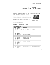
... LED readout located directly onboard the motherboard. This Debug LED will also display current CPU temperatures after the system has fully booted into the Operating System. POST Codes This section provides the Award POST Codes (Table 6) for the EVGA X58 FTW3 Motherboard during system boot up. Award POST Code Award POST Codes Code Name... the super IO Reset Video controller Keyboard controller init Test the Keyboard Initialized the mouse Check the integrity of the ROM,BIOS and message 67 EVGA X58 SLI Motherboard Appendix A.
... LED readout located directly onboard the motherboard. This Debug LED will also display current CPU temperatures after the system has fully booted into the Operating System. POST Codes This section provides the Award POST Codes (Table 6) for the EVGA X58 FTW3 Motherboard during system boot up. Award POST Code Award POST Codes Code Name... the super IO Reset Video controller Keyboard controller init Test the Keyboard Initialized the mouse Check the integrity of the ROM,BIOS and message 67 EVGA X58 SLI Motherboard Appendix A.

User Guide
Page 68
EVGA X58 FTW3 Motherboard Award POST Codes Code Name 0F Reserved Description 10 Autodetect EEPROM Check Flash type and copy flash write...CMOS 13 Reserved 14 Load Chipset Load Chipset Defaults 15 Reserved 16 Init Clock Initialize onboard clock generator 17 Reserved 18 Init CPU CPU ID and initialize L1/L2 cache 19 Reserved 1A Reserved 1B Setup Interrupt Initialize first 120 interrupt vectors with Vector Table ... Gen Init onboard clock generator and sensor 27 Setup BDA Setup BIOS DATA AREA (BDA) 28 Reserved 29 CPU Speed Chipset programming and CPU Speed detect 68
EVGA X58 FTW3 Motherboard Award POST Codes Code Name 0F Reserved Description 10 Autodetect EEPROM Check Flash type and copy flash write...CMOS 13 Reserved 14 Load Chipset Load Chipset Defaults 15 Reserved 16 Init Clock Initialize onboard clock generator 17 Reserved 18 Init CPU CPU ID and initialize L1/L2 cache 19 Reserved 1A Reserved 1B Setup Interrupt Initialize first 120 interrupt vectors with Vector Table ... Gen Init onboard clock generator and sensor 27 Setup BDA Setup BIOS DATA AREA (BDA) 28 Reserved 29 CPU Speed Chipset programming and CPU Speed detect 68