
PDF Spec Sheet
Page 1
More Gold Content - 1JL,1 I WARRANTY This product is available upon registration within 30 days of a button Mit Onboard CPU Temperature Monitor Monitor your PC on an external adapter! DIMENSIONS i l i l i l i • Width: 10.375in - 263.5mm • Length: 12in ... State Capacitors Higher quality, longer lifespan - For more details please visit www.evga.com/warranty/ 61? Bonus Storage Integrated Flash Storage Use as storage, swap file, anything PCI-E Disable Jumpers Quickly and easily troubleshoot! 3 A Z68 FTW Part Number: 160-SB-E689 VC USB 3 & SATA 3/6G 1Z,VdZ...
More Gold Content - 1JL,1 I WARRANTY This product is available upon registration within 30 days of a button Mit Onboard CPU Temperature Monitor Monitor your PC on an external adapter! DIMENSIONS i l i l i l i • Width: 10.375in - 263.5mm • Length: 12in ... State Capacitors Higher quality, longer lifespan - For more details please visit www.evga.com/warranty/ 61? Bonus Storage Integrated Flash Storage Use as storage, swap file, anything PCI-E Disable Jumpers Quickly and easily troubleshoot! 3 A Z68 FTW Part Number: 160-SB-E689 VC USB 3 & SATA 3/6G 1Z,VdZ...

User Guide
Page 6
... to install the motherboard into a PC case. If however, you are building a PC, you will need many of supported CPU's on this motherboard, please visit http://www.evga.com/support/motherboard/. For a full list of the cables. However, it does not contain the following items that must be... separately to make the motherboard functional. Intel Socket 1155 Processor DDR3 System Memory Socket 775 or 1155/1156 CPU cooler for proper system functionality. EVGA Z68/P67 Motherboard This kit contains all the necessary parts needed to install and connect your new...
... to install the motherboard into a PC case. If however, you are building a PC, you will need many of supported CPU's on this motherboard, please visit http://www.evga.com/support/motherboard/. For a full list of the cables. However, it does not contain the following items that must be... separately to make the motherboard functional. Intel Socket 1155 Processor DDR3 System Memory Socket 775 or 1155/1156 CPU cooler for proper system functionality. EVGA Z68/P67 Motherboard This kit contains all the necessary parts needed to install and connect your new...

User Guide
Page 11
EVGauge (Optional) Analog Gauge that represents your EVGA Motherboard. EVGA Z68/P67 Motherboard - User Manual Contains Information needed to properly install and configure your CPU frequency in real time. - Installation CD Contains drivers and soare needed to setup the motherboard. - ECP Panel (Optional) Allows monitoring of post codes and remote control of PCIe slot disable, voltages and CMOS reset all on one bay mounted panel. -
EVGauge (Optional) Analog Gauge that represents your EVGA Motherboard. EVGA Z68/P67 Motherboard - User Manual Contains Information needed to properly install and configure your CPU frequency in real time. - Installation CD Contains drivers and soare needed to setup the motherboard. - ECP Panel (Optional) Allows monitoring of post codes and remote control of PCIe slot disable, voltages and CMOS reset all on one bay mounted panel. -
User Guide
Page 12
Remember to remove power from your computer by disconnecting the AC main source before removing or installing any equipment from/to the computer chassis. The topics covered in this section are: Preparing the motherboard Installing the CPU Installing the CPU fan Installing the memory Installing the motherboard Connecting cables To reduce the risk of the motherboard. EVGA Z68/P67 Motherboard This section will guide you through the installation of fire, electric shock, and injury, always follow basic safety precautions.
Remember to remove power from your computer by disconnecting the AC main source before removing or installing any equipment from/to the computer chassis. The topics covered in this section are: Preparing the motherboard Installing the CPU Installing the CPU fan Installing the memory Installing the motherboard Connecting cables To reduce the risk of the motherboard. EVGA Z68/P67 Motherboard This section will guide you through the installation of fire, electric shock, and injury, always follow basic safety precautions.

User Guide
Page 13
... for any reason you can replace the cover to protect the socket when there is a protective socket cover within the CPU socket to avoid damaging the CPU socket pins. Pull the socket lever back and the load plate will automatically lift. Hold the processor only by pushing down and away... from the CPU Socket. Use the following procedure to install the CPU onto the motherboard: Unhook the socket lever by the edges and do not touch the bottom of the processor. EVGA Z68/P67 Motherboard Be very careful when handling the...
... for any reason you can replace the cover to protect the socket when there is a protective socket cover within the CPU socket to avoid damaging the CPU socket pins. Pull the socket lever back and the load plate will automatically lift. Hold the processor only by pushing down and away... from the CPU Socket. Use the following procedure to install the CPU onto the motherboard: Unhook the socket lever by the edges and do not touch the bottom of the processor. EVGA Z68/P67 Motherboard Be very careful when handling the...

User Guide
Page 14
... are many different fan types that there are 2 sets of mounting holes, there are labeled. Note: Make sure the CPU is complete. The CPU installation is fully seated and level in the processor with your fan assembly. Follow the instruction that the fan orientation is correct for.... In most cases, the Socket 1156/1155 mounting holes will be used . Please note that can be used with notches on the socket. EVGA Z68/P67 Motherboard Align the notches in the socket. Align notches with this motherboard. Lower the processor straight down while you close and engage the socket...
... are many different fan types that there are 2 sets of mounting holes, there are labeled. Note: Make sure the CPU is complete. The CPU installation is fully seated and level in the processor with your fan assembly. Follow the instruction that the fan orientation is correct for.... In most cases, the Socket 1156/1155 mounting holes will be used . Please note that can be used with notches on the socket. EVGA Z68/P67 Motherboard Align the notches in the socket. Align notches with this motherboard. Lower the processor straight down while you close and engage the socket...

User Guide
Page 16
... comes with an I /O shield into place and make all the connections. Also Note that for the expansion cards. Press the I /O shield that the CPU fan assembly has enough clearance for the system case covers to lock into place and for ease of installation you would be easier to make...this step or to secure the motherboard and then make sure it would need to obtain the proper size from the inside of the chassis. EVGA Z68/P67 Motherboard The sequence of installing the motherboard into a system case depends on the system case being used to block radio frequency transmissions, ...
... comes with an I /O shield into place and make all the connections. Also Note that for the expansion cards. Press the I /O shield that the CPU fan assembly has enough clearance for the system case covers to lock into place and for ease of installation you would be easier to make...this step or to secure the motherboard and then make sure it would need to obtain the proper size from the inside of the chassis. EVGA Z68/P67 Motherboard The sequence of installing the motherboard into a system case depends on the system case being used to block radio frequency transmissions, ...
User Guide
Page 19
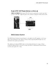
This jumper controls which of physical BIOS chips are to be used to provide power to the CPU. Align the pins to differentiate between bench sessions and regular 24/7 usage. EVGA Z68/P67 Motherboard PW12-1 & PW12-2, the 8-pin ATX 12V power connection, is used when the system is located directly to the right of...
This jumper controls which of physical BIOS chips are to be used to provide power to the CPU. Align the pins to differentiate between bench sessions and regular 24/7 usage. EVGA Z68/P67 Motherboard PW12-1 & PW12-2, the 8-pin ATX 12V power connection, is used when the system is located directly to the right of...

User Guide
Page 26
This LED will also display current CPU socket temperatures after the system has fully booted into the Operating System. POWER LED (GREEN) STANDBY LED (BLUE) DIMM LED (YELLOW) EVGA Z68/P67 Motherboard Provides two-digit POST codes to show why the system may be failing to boot. This Debug LED ...will remain on . Debug LED with CPU Temperature Monitor Theses LEDs indicate the system's status. POWER LED...
This LED will also display current CPU socket temperatures after the system has fully booted into the Operating System. POWER LED (GREEN) STANDBY LED (BLUE) DIMM LED (YELLOW) EVGA Z68/P67 Motherboard Provides two-digit POST codes to show why the system may be failing to boot. This Debug LED ...will remain on . Debug LED with CPU Temperature Monitor Theses LEDs indicate the system's status. POWER LED...

User Guide
Page 28
...Power on the Debug LED readout located directly onboard the motherboard. Debug LED with CPU Temperature Monitor Table 6. Pre-memory CPU initialization is started 18 19- This Debug LED will also display current CPU temperatures after microcode loading 0B Cache initialization 0C- Reset type detection (soft/hard...fully booted into the Operating System. Pre-memory North Bridge initialization is started 14 15- Pre-memory South Bridge initialization is started EVGA Z68/P67 Motherboard This section provides the AMI POST Codes (Table 6) for future AMI SEC error codes 0D 0E Microcode not found ...
...Power on the Debug LED readout located directly onboard the motherboard. Debug LED with CPU Temperature Monitor Table 6. Pre-memory CPU initialization is started 18 19- This Debug LED will also display current CPU temperatures after microcode loading 0B Cache initialization 0C- Reset type detection (soft/hard...fully booted into the Operating System. Pre-memory North Bridge initialization is started 14 15- Pre-memory South Bridge initialization is started EVGA Z68/P67 Motherboard This section provides the AMI POST Codes (Table 6) for future AMI SEC error codes 0D 0E Microcode not found ...

User Guide
Page 29
...). 30 Reserved for ASL (see ASL Status Codes section below) 31 Memory Installed 32 CPU post-memory initialization is started 33 CPU post-memory initialization. Cache initialization 34 CPU post-memory initialization. OEM post memory initialization codes 4E 4F DXE IPL is started 50 ...code update Invalid memory type or incompatible memory speed 51 Memory initialization error. Boot Strap Processor (BSP) selection 36 CPU post-memory initialization. EVGA Z68/P67 Motherboard 1C 1D- OEM pre-memory initialization codes 2A 2B Memory initialization. Serial Presence Detect (SPD) data ...
...). 30 Reserved for ASL (see ASL Status Codes section below) 31 Memory Installed 32 CPU post-memory initialization is started 33 CPU post-memory initialization. Cache initialization 34 CPU post-memory initialization. OEM post memory initialization codes 4E 4F DXE IPL is started 50 ...code update Invalid memory type or incompatible memory speed 51 Memory initialization error. Boot Strap Processor (BSP) selection 36 CPU post-memory initialization. EVGA Z68/P67 Motherboard 1C 1D- OEM pre-memory initialization codes 2A 2B Memory initialization. Serial Presence Detect (SPD) data ...

User Guide
Page 30
... F1 Recovery condition triggered by the DXE IPL) E1 S3 Boot Script execution E2 Video repost E3 OS S3 wake vector call E4- CPU DXE initialization is started 67 68 PCI host bridge initialization 69 North Bridge DXE initialization is started 6A North Bridge DXE SMM initialization is... by user (Forced recovery) F2 Recovery process started 61 NVRAM initialization 62 Installation of the South Bridge Runtime Services 63- EVGA Z68/P67 Motherboard is failed 5A Internal CPU error 5B reset PPI is started 6B- North Bridge DXE initialization (North Bridge 6F module specific) 70 South Bridge DXE ...
... F1 Recovery condition triggered by the DXE IPL) E1 S3 Boot Script execution E2 Video repost E3 OS S3 wake vector call E4- CPU DXE initialization is started 67 68 PCI host bridge initialization 69 North Bridge DXE initialization is started 6A North Bridge DXE SMM initialization is... by user (Forced recovery) F2 Recovery process started 61 NVRAM initialization 62 Installation of the South Bridge Runtime Services 63- EVGA Z68/P67 Motherboard is failed 5A Internal CPU error 5B reset PPI is started 6B- North Bridge DXE initialization (North Bridge 6F module specific) 70 South Bridge DXE ...

User Guide
Page 32
OEM BDS initialization codes CF D0 CPU initialization error D1 North Bridge initialization error D2 South Bridge initialization error D3 Some of the Architectural Protocols are found D7 No Console Input Devices are not available D4 PCI resource allocation error. EVGA Z68/P67 Motherboard AD Ready To Boot event AE Legacy Boot event AF...
OEM BDS initialization codes CF D0 CPU initialization error D1 North Bridge initialization error D2 South Bridge initialization error D3 Some of the Architectural Protocols are found D7 No Console Input Devices are not available D4 PCI resource allocation error. EVGA Z68/P67 Motherboard AD Ready To Boot event AE Legacy Boot event AF...
User Guide
Page 33
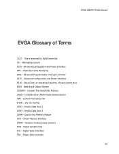
Advanced Programmable Interrupt Controller ACPI - Complementary Metal-Oxide Semiconductor CPU - Direct Memory Interface DRAM - Dynamic random access memory DVD - Base Clock (or operating frequency of base system bus) BIOS - Compact ... Configuration and Power Interface BCLK - Double Data Rate 2 DDR3 - Alternating Current ACPI - Central Processing Unit D-ICE - Dual In-line Memory Module DMI - EVGA Z68/P67 Motherboard 1337 - Advanced Configuration and Power Interface AFR - Digital Video Interface FDC - Floppy Disk Controller Double Data Rate 3 DIMM - Digital Versatile Disc DVI...
Advanced Programmable Interrupt Controller ACPI - Complementary Metal-Oxide Semiconductor CPU - Direct Memory Interface DRAM - Dynamic random access memory DVD - Base Clock (or operating frequency of base system bus) BIOS - Compact ... Configuration and Power Interface BCLK - Double Data Rate 2 DDR3 - Alternating Current ACPI - Central Processing Unit D-ICE - Dual In-line Memory Module DMI - EVGA Z68/P67 Motherboard 1337 - Advanced Configuration and Power Interface AFR - Digital Video Interface FDC - Floppy Disk Controller Double Data Rate 3 DIMM - Digital Versatile Disc DVI...
