
Use and Care Guide
Page 8
... Fig. 1 - 30" model _I0 _7 Fig. 2 - 36" Model i i: ii iiiiiiiiiiiiiiiiiiiiiiiiii!ii!iii!iiiii!ii!ii_!iiii_iiii"ii!_"!_!ii_:ii'i_!i_iiiiiiiii!i_i)iii!!i_ii!_i_ii!l!i!i__i!l!!_!!_!_i_ii!i_i!i_i_!!_!!! Cooktop Features READ THESE INSTRUCTIONS CAREFULLY BEFORE USING THE COOKTOP INDUCTIONELEMENT CHA_CTERISTHCS (RIGHFTRONTANDREARELEMENTS) A COOLER COOKTOP- EFFICIENT- Right Rear Single Induction Element 4. Left Rear Single Radiant Element...
... Fig. 1 - 30" model _I0 _7 Fig. 2 - 36" Model i i: ii iiiiiiiiiiiiiiiiiiiiiiiiii!ii!iii!iiiii!ii!ii_!iiii_iiii"ii!_"!_!ii_:ii'i_!i_iiiiiiiii!i_i)iii!!i_ii!_i_ii!l!i!i__i!l!!_!!_!_i_ii!i_i!i_i_!!_!!! Cooktop Features READ THESE INSTRUCTIONS CAREFULLY BEFORE USING THE COOKTOP INDUCTIONELEMENT CHA_CTERISTHCS (RIGHFTRONTANDREARELEMENTS) A COOLER COOKTOP- EFFICIENT- Right Rear Single Induction Element 4. Left Rear Single Radiant Element...
Use and Care Guide
Page 10
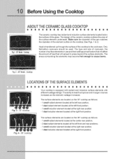
... at the left rear position; - 1 dual radiant element located at the left front and rear positions; - 1 small induction element located at the right rear position; - 1 dual induction element located at the right front position, Fig. 4 - 36" cooktop The surface elements are all factors that will affect the amount of heat that will spread to...
... at the left rear position; - 1 dual radiant element located at the left front and rear positions; - 1 small induction element located at the right rear position; - 1 dual induction element located at the right front position, Fig. 4 - 36" cooktop The surface elements are all factors that will affect the amount of heat that will spread to...

Use and Care Guide
Page 19
... indicate which coil of the element. size Fig. 2 5. Fig. 3 Fig. 4 Surface Controls OPERATINGTHE DUAL SURFACERADIANT ELEMENT Both the 30" and 36" cooktops are used to power the element ON will turn ON. Start most cooking operations on display for the surface heating area, 8. When cooking has been...as shown in Figs. 1 & 2. Symbols and indicator lights on the radiant surface element, 2. Touch hi + pad once to turn off the POWER cooktop.Note: The Hot Element (HE) message will heat. To Operate the Dual Surface Element: 1. Touch and hold the C) key pad until a beep ...
... indicate which coil of the element. size Fig. 2 5. Fig. 3 Fig. 4 Surface Controls OPERATINGTHE DUAL SURFACERADIANT ELEMENT Both the 30" and 36" cooktops are used to power the element ON will turn ON. Start most cooking operations on display for the surface heating area, 8. When cooking has been...as shown in Figs. 1 & 2. Symbols and indicator lights on the radiant surface element, 2. Touch hi + pad once to turn off the POWER cooktop.Note: The Hot Element (HE) message will heat. To Operate the Dual Surface Element: 1. Touch and hold the C) key pad until a beep ...
Installation Instructions
Page 1
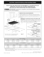
... liquids in the cabinet * 30" (76.2 cm) min. pages 6-1O; for protected surface Figure 1 Figure 1-B 30" Model 36" Model 293A (75.6) 36 (91.4) 30 (76.2) 36¼(92.1) 203/8 (51.8) 203/8 (51.8) 20Y2 (52.1) 20h (52.1) 8V2 (21.6) 8Y2 (21.6) All dimensions are...volt, 60 hertz, AC only electrical supply with ground. • Minimum distance between cooktop and overhead cabinetry is installed over a wall oven. Notes - 16 Printed in inches (cm). * Allow 2" (5 cm) space below cooktop to route armored cable. Espar_ol - iMPORTANT: SAVE FOR LOCAL ELECTRICAL iNSPECTOR'S USE. B...
... liquids in the cabinet * 30" (76.2 cm) min. pages 6-1O; for protected surface Figure 1 Figure 1-B 30" Model 36" Model 293A (75.6) 36 (91.4) 30 (76.2) 36¼(92.1) 203/8 (51.8) 203/8 (51.8) 20Y2 (52.1) 20h (52.1) 8V2 (21.6) 8Y2 (21.6) All dimensions are...volt, 60 hertz, AC only electrical supply with ground. • Minimum distance between cooktop and overhead cabinetry is installed over a wall oven. Notes - 16 Printed in inches (cm). * Allow 2" (5 cm) space below cooktop to route armored cable. Espar_ol - iMPORTANT: SAVE FOR LOCAL ELECTRICAL iNSPECTOR'S USE. B...

Installation Instructions
Page 2
... horizontally a minimum of 5" (12.7 cm) beyond the bottom of the cabinets. 30" Ceramic Glass 36" Ceramic Glass 7½" (19.1 cm) 7½" (19.1 cm) 2" (5.1 cm) 2" (5.1 cm) Figure 2 - From Edge of Cooktop to Front Edge of an Unprotected Wood or Metal Cabinet. _ _j, 24" (61 cm) Min.... the Top of the Cooking_nceBetwe_ _ Platform and the Bottom of Countertop It is not recommended to chart on this figure refer to use drawer underneath cooktop. Recommended _ ,. _ | | 18" (45.7 cm) I I _ ¢,,t_,,t_ Rear a Edge of Cutout and Nearest Combustible 10" Surface Above ( 25.4 cm) Countertop ...
... horizontally a minimum of 5" (12.7 cm) beyond the bottom of the cabinets. 30" Ceramic Glass 36" Ceramic Glass 7½" (19.1 cm) 7½" (19.1 cm) 2" (5.1 cm) 2" (5.1 cm) Figure 2 - From Edge of Cooktop to Front Edge of an Unprotected Wood or Metal Cabinet. _ _j, 24" (61 cm) Min.... the Top of the Cooking_nceBetwe_ _ Platform and the Bottom of Countertop It is not recommended to chart on this figure refer to use drawer underneath cooktop. Recommended _ ,. _ | | 18" (45.7 cm) I I _ ¢,,t_,,t_ Rear a Edge of Cutout and Nearest Combustible 10" Surface Above ( 25.4 cm) Countertop ...

