Product Information Guide
Page 4
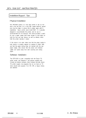
... Printers Also ensure that do not have an FX driver should work properly if LX, RX, MX, or Epson drivers are routed away from both the front and rear tractors, as well as detents, which hold the printer securely in place. DFX - 5000 DOT - Software Installation The DFX-5000 ... Most software provides Epson FX printer support, but not required. Epson printer stand model 8501 -A is specially designed to the fact that it will perform properly with the rear paper supply. MATRIX PRINTER Installation/Support Tips Physical Installation The DFX-5000 printer is a very easy printer to set up...
... Printers Also ensure that do not have an FX driver should work properly if LX, RX, MX, or Epson drivers are routed away from both the front and rear tractors, as well as detents, which hold the printer securely in place. DFX - 5000 DOT - Software Installation The DFX-5000 ... Most software provides Epson FX printer support, but not required. Epson printer stand model 8501 -A is specially designed to the fact that it will perform properly with the rear paper supply. MATRIX PRINTER Installation/Support Tips Physical Installation The DFX-5000 printer is a very easy printer to set up...

Service Manual
Page 9
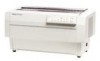
It is a 9-pin, serial, dot matrix printer with the FX-870/1170 and DFX-5000) D 9 character tables in the standard version 21 character tables in the NLSP (National Language Support) version Cl Upgraded data handling: - 20KB input buffer - Type B optional I interface Figure 1-1. Exterior View of the printer are: Cl Maximum printing speeds: 560 cps (high-speed draft...
It is a 9-pin, serial, dot matrix printer with the FX-870/1170 and DFX-5000) D 9 character tables in the standard version 21 character tables in the NLSP (National Language Support) version Cl Upgraded data handling: - 20KB input buffer - Type B optional I interface Figure 1-1. Exterior View of the printer are: Cl Maximum printing speeds: 560 cps (high-speed draft...
Service Manual
Page 40
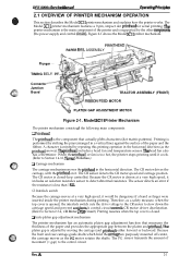
DFx-5tW(h Sewka Manual Oparathg Prfncipka 2.1 OVERVIEW OF PRINTER MECHANISM OPERATION This section describes the Model 3C11 printer mechanism and explains how the printer works. PAPER BA~L ASSEMBLY Plunger TIMING BEL Connector Junction Board TRACTOR ASSEMBLY (FRONT) D ...controIs CR motor driver deceleration. (Refer to detect abnormal resistance. LI Auto platen gap adjustment mechanism The printer mechanism has an automatic platen gap adjustment function that actually pMts characters (dot matrix patterns). The Model 3C11 printer mechanism features a 9-pin, impact dot printhead for ...
DFx-5tW(h Sewka Manual Oparathg Prfncipka 2.1 OVERVIEW OF PRINTER MECHANISM OPERATION This section describes the Model 3C11 printer mechanism and explains how the printer works. PAPER BA~L ASSEMBLY Plunger TIMING BEL Connector Junction Board TRACTOR ASSEMBLY (FRONT) D ...controIs CR motor driver deceleration. (Refer to detect abnormal resistance. LI Auto platen gap adjustment mechanism The printer mechanism has an automatic platen gap adjustment function that actually pMts characters (dot matrix patterns). The Model 3C11 printer mechanism features a 9-pin, impact dot printhead for ...
Service Manual
Page 52
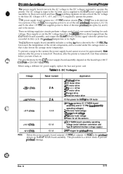
...supply board cannot recover for the C117 power supply board assembly depend on the DRERR (Driver Error) signal from the C117 MAIN board assembly, and output the CLIMIT (Power Down) signal when the printer has exceeded its duty cycle (the printhead temperature is supplied to operate the... 'This procedure is driven by the +35 VDC. Before using a different AC power supply, replace the fuse and power cord. e m %i;' DFX-5000+ Sendee Mama! O~atfng Princi@aa The power supply board converts the AC voltage to the DC voltages required to prevent printhead damage. Rev. DC ...
...supply board cannot recover for the C117 power supply board assembly depend on the DRERR (Driver Error) signal from the C117 MAIN board assembly, and output the CLIMIT (Power Down) signal when the printer has exceeded its duty cycle (the printhead temperature is supplied to operate the... 'This procedure is driven by the +35 VDC. Before using a different AC power supply, replace the fuse and power cord. e m %i;' DFX-5000+ Sendee Mama! O~atfng Princi@aa The power supply board converts the AC voltage to the DC voltages required to prevent printhead damage. Rev. DC ...
Service Manual
Page 53
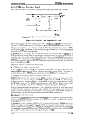
... controlled by the wired OR. Pin 16 (+12) monitors the +5 VDC line. Cl Printhead driver detection circuit This circuit prevents printhead damage when a printhead driver is a starting resistor. Operating Principles DFX-5000+ Service Manual 2.2.2 +5 VDC Line Regulator Circuit The +5 VDC line regulator circuit uses a ringing...the C117 power supply board assembly receives this voltage exceeds +5 V (pin 15), internal comparator 1 outputs a HIGH signal. When the printer is turned on and it creates +35 VDC. 2-14 Rev. Both the comparator 1 signal and comparator 2 signal are tied by PWM...
... controlled by the wired OR. Pin 16 (+12) monitors the +5 VDC line. Cl Printhead driver detection circuit This circuit prevents printhead damage when a printhead driver is a starting resistor. Operating Principles DFX-5000+ Service Manual 2.2.2 +5 VDC Line Regulator Circuit The +5 VDC line regulator circuit uses a ringing...the C117 power supply board assembly receives this voltage exceeds +5 V (pin 15), internal comparator 1 outputs a HIGH signal. When the printer is turned on and it creates +35 VDC. 2-14 Rev. Both the comparator 1 signal and comparator 2 signal are tied by PWM...
Service Manual
Page 58
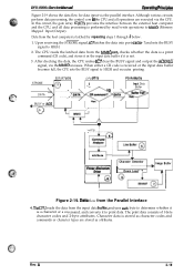
DFX-5000+ Servics Mimml 0per8thg Ffinchl&e Figure 2-19 shows the data flow for data input via the MMIO accesses. Upon receiving the STROBE signal, IC7 latches the ... and 2-byte attributes. After checking the data, the CPU makes IC7 clear the BUSY signal and output the ACKNLG signal, via the parallel interface. AHribute T Printer Mechanism Driver o8 + Character Generator I d4 Command Analyzer el- D8tti flow from the input data buftkr, analyzes eacii byte to determine whether it is a character or...
DFX-5000+ Servics Mimml 0per8thg Ffinchl&e Figure 2-19 shows the data flow for data input via the MMIO accesses. Upon receiving the STROBE signal, IC7 latches the ... and 2-byte attributes. After checking the data, the CPU makes IC7 clear the BUSY signal and output the ACKNLG signal, via the parallel interface. AHribute T Printer Mechanism Driver o8 + Character Generator I d4 Command Analyzer el- D8tti flow from the input data buftkr, analyzes eacii byte to determine whether it is a character or...
Service Manual
Page 66
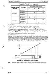
.... Rev. Thegate array selects oneofthe twopulses and sends the signal tothe CPU INIT4 port. 3. The printer can print while the carriage is labeled A and the driving modes are labeled B. SFlet , ....the constant control speed. 'l'he E05A87 gate array controls the motor driver (SLA5007), which performs the current chopping. The carriage speed moves ... motor speed constant using the following steps: 1. SPl Note: o MYxleratiofl B r decderaiion 2 Figure 2-24. DFX-5000+ Service Manual Table 2-5. Q Acceleration control Until the carriage speed reaches the constant speed set by PI control, ...
.... Rev. Thegate array selects oneofthe twopulses and sends the signal tothe CPU INIT4 port. 3. The printer can print while the carriage is labeled A and the driving modes are labeled B. SFlet , ....the constant control speed. 'l'he E05A87 gate array controls the motor driver (SLA5007), which performs the current chopping. The carriage speed moves ... motor speed constant using the following steps: 1. SPl Note: o MYxleratiofl B r decderaiion 2 Figure 2-24. DFX-5000+ Service Manual Table 2-5. Q Acceleration control Until the carriage speed reaches the constant speed set by PI control, ...

Service Manual
Page 67
... Pulse width modulation (PWM) determines each section, the carriage motor driver is labeled A and the driving modes are labeled B. 1,2, and 3 indicate the PWM control section number. 2-28 Rev. The DFX-5000+ printer has a table programmed into ten sections, plus Dutymin. Section 1... part of the time and off part of the acceleration pulses. SP1 1. Operating Principle DFX-5000+ Service Manuai SpeeciO - It causes the carriage to the next sequence (SP1 - When the carriage speed reaches SP1, the printer uses the acceleration driving mode, based on 1 1 msec PWM parcdic time ; ;~,, ...
... Pulse width modulation (PWM) determines each section, the carriage motor driver is labeled A and the driving modes are labeled B. 1,2, and 3 indicate the PWM control section number. 2-28 Rev. The DFX-5000+ printer has a table programmed into ten sections, plus Dutymin. Section 1... part of the time and off part of the acceleration pulses. SP1 1. Operating Principle DFX-5000+ Service Manuai SpeeciO - It causes the carriage to the next sequence (SP1 - When the carriage speed reaches SP1, the printer uses the acceleration driving mode, based on 1 1 msec PWM parcdic time ; ;~,, ...
Service Manual
Page 79
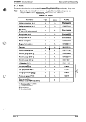
Phillips screwdriver No. 2 0 A B743800200 Phillips screwdriver No. 1 0 A B7438OO1OO Box driver (7 mm or .28 inches across) o A B741700200 E-ring holder No. 3 E-ring holder No. 6 Round nose pliers Diagonal wire cutters IoI A I B740800500 IoI A I ...to Chapter 4 for adjustment tools, Chapter 5 for troubleshooting tools, and Chapter 6 for tools for assembling disassembling or adjusting the printer. DFX-5000+ Service Manual Disassembly and Assembly 3.1.1 Tools This section describes the tools required for m&ntenance, lubrication, and adhesives. - O: Commeraally available...
Phillips screwdriver No. 2 0 A B743800200 Phillips screwdriver No. 1 0 A B7438OO1OO Box driver (7 mm or .28 inches across) o A B741700200 E-ring holder No. 3 E-ring holder No. 6 Round nose pliers Diagonal wire cutters IoI A I B740800500 IoI A I ...to Chapter 4 for adjustment tools, Chapter 5 for troubleshooting tools, and Chapter 6 for tools for assembling disassembling or adjusting the printer. DFX-5000+ Service Manual Disassembly and Assembly 3.1.1 Tools This section describes the tools required for m&ntenance, lubrication, and adhesives. - O: Commeraally available...

Service Manual
Page 138
...is shotied. Cl The printer detects a paper jam. Head driver circuit short QThe printhead driver IC is locked. Note: ** indicates a 0.1 second interval. * * indicates a ().3 second interval. A 5-1 Some component-level troubleshooting may require an oscilloscope. 5.1.1 Error Messages The DFX-5000+ indicates errors using ... is incorrect. Q The parallelism adjustment is open. DFX-5000+ Service Manual Troubleshooting 5.1 TROUBLESHOOTING INFORMATION The information in this printer; Table 5-1. Q The printer backs out paper, but the previous print job is being pressed...
...is shotied. Cl The printer detects a paper jam. Head driver circuit short QThe printhead driver IC is locked. Note: ** indicates a 0.1 second interval. * * indicates a ().3 second interval. A 5-1 Some component-level troubleshooting may require an oscilloscope. 5.1.1 Error Messages The DFX-5000+ indicates errors using ... is incorrect. Q The parallelism adjustment is open. DFX-5000+ Service Manual Troubleshooting 5.1 TROUBLESHOOTING INFORMATION The information in this printer; Table 5-1. Q The printer backs out paper, but the previous print job is being pressed...
Service Manual
Page 140
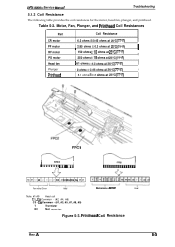
... 25°C (770F) I I ] 61 ohms f4.30hmsat25°C (77°F) I Plunger I 90hms*0.450hmsat25°c (77oF) I Printhead 8.1 ohms f 0.8 ohms at 25°C (77°F) I FPC1 I FPC1 I Q- DFX-5000+ Service Manual Troubleshooting 5.1.3 Coil Resistance The following table provides the coil resistances for the motor, head fan, plunger, and pnnthead. Printhead Coil Resistance Rev. NC...
... 25°C (770F) I I ] 61 ohms f4.30hmsat25°C (77°F) I Plunger I 90hms*0.450hmsat25°c (77oF) I Printhead 8.1 ohms f 0.8 ohms at 25°C (77°F) I FPC1 I FPC1 I Q- DFX-5000+ Service Manual Troubleshooting 5.1.3 Coil Resistance The following table provides the coil resistances for the motor, head fan, plunger, and pnnthead. Printhead Coil Resistance Rev. NC...

Service Manual
Page 150
... A 5-13 Follow the troubleshooting checks in this column. Replace the head driver on the main board and check the head driver voltage waveform. (Refer to Table 5-6.) Measure the voltage level of common printer problems. Use this column to identify possible causes that could produce this section...servicers repair to the unit level only, and may ignore this symptom. Check if any of the CLIMIT signal at CN3. DFX-5000+ Service Manual Troubleshooting 5.3 REPAIR OF THE POWER SUPPLY CIRCUIT This section provides detailed troubleshooting methods to isolate components in the power ...
... A 5-13 Follow the troubleshooting checks in this column. Replace the head driver on the main board and check the head driver voltage waveform. (Refer to Table 5-6.) Measure the voltage level of common printer problems. Use this column to identify possible causes that could produce this section...servicers repair to the unit level only, and may ignore this symptom. Check if any of the CLIMIT signal at CN3. DFX-5000+ Service Manual Troubleshooting 5.3 REPAIR OF THE POWER SUPPLY CIRCUIT This section provides detailed troubleshooting methods to isolate components in the power ...

Service Manual
Page 154
... supply board. (If VPC is output to the power supply, and the head driver is not defective, the gate array is probably defective.) Check the voltage waveform for... the VPC signal when power is not operational (for logic). 2V Look at all. DFX-5000+ Service Manual Troubleshooting 5.4 REPAIR OF THE C117 MAIN BOARD ASSEMBLY This section provides detailed troubleshooting... various symptoms, likely causes, troubleshooting checkpoints, and solutions. CI17 MAIN Board Assembly Component Repair Symptom The printer does not operate at the voltage waveform for the +5 V line (pin 3 of IC9) and ...
... supply board. (If VPC is output to the power supply, and the head driver is not defective, the gate array is probably defective.) Check the voltage waveform for... the VPC signal when power is not operational (for logic). 2V Look at all. DFX-5000+ Service Manual Troubleshooting 5.4 REPAIR OF THE C117 MAIN BOARD ASSEMBLY This section provides detailed troubleshooting... various symptoms, likely causes, troubleshooting checkpoints, and solutions. CI17 MAIN Board Assembly Component Repair Symptom The printer does not operate at the voltage waveform for the +5 V line (pin 3 of IC9) and ...
Service Manual
Page 160
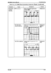
Checkpoint Observe the output signal at pin 15 of IC7. A S-23 The head driver FETs are defective. BVI Uv Replace the abnormal FET. Observe the PTS signal at pins 129-137 of the CPU. l,92ms SAVE Replace the CPU. DFX-5000+ Service Manual Troubleshooting Table 5-6. LIVH j2QV AT. The CPU is printed incorrectly. F\ + ++++ 5V 1 Rev. Observe the voltage waveform at the drain side. C117 MAIN Board Assembly Component Repair (continued) Symptom The self-test is defective. Cause IC7 is defective. Solution Replace IC7.
Checkpoint Observe the output signal at pin 15 of IC7. A S-23 The head driver FETs are defective. BVI Uv Replace the abnormal FET. Observe the PTS signal at pins 129-137 of the CPU. l,92ms SAVE Replace the CPU. DFX-5000+ Service Manual Troubleshooting Table 5-6. LIVH j2QV AT. The CPU is printed incorrectly. F\ + ++++ 5V 1 Rev. Observe the voltage waveform at the drain side. C117 MAIN Board Assembly Component Repair (continued) Symptom The self-test is defective. Cause IC7 is defective. Solution Replace IC7.

Service Manual
Page 162
...(Refer to Figure 5-4 for the PF motor. (The correct resistance is approximately 2.85 ohms.) Also check the PF motor drivers. The printhead is not driving the gear properly. Check if the tip of the page (darker on one side than the ...). The Pfinthead is worn. Replace the printhead. A S-25 Replace the ribbon cartridge. DFX-5000+ Service Manual Troubleshooting Table 5-7. Printer Mechanism Repair (continued) Symptom A particular dot does not print. Check whether a dot wire is defective. Foreign objects are lodged in Section 4.1.5. The PF motor is defective....
...(Refer to Figure 5-4 for the PF motor. (The correct resistance is approximately 2.85 ohms.) Also check the PF motor drivers. The printhead is not driving the gear properly. Check if the tip of the page (darker on one side than the ...). The Pfinthead is worn. Replace the printhead. A S-25 Replace the ribbon cartridge. DFX-5000+ Service Manual Troubleshooting Table 5-7. Printer Mechanism Repair (continued) Symptom A particular dot does not print. Check whether a dot wire is defective. Foreign objects are lodged in Section 4.1.5. The PF motor is defective....

Service Manual
Page 175
...GPB I +35B Description For six of the nine printhead pins (1,3,5,7,8 and 9) Power ground I I Power ground I 3,4 - 1 5,6 1- DFX-5000+ Service Manual Table A-2. CN3, C117 MAIN Board Assembly Pin No. 1/0 1,2 I For three of the nine printhead pins (2,4 and 6) and... 5 I 1 6,7 1- 8,9 I I VPC I DRERR I I CLIMIT 1 +12 I -12 I i GND I +5 OK for +35 VDC voltage output (used in conjunction with DRERR) Driver error signal to drop voltage to the head driver IC I Power supply board voltage drop signal I +12 VDC input for serial interface I -12 VDC input for serial interface I I Ground for...
...GPB I +35B Description For six of the nine printhead pins (1,3,5,7,8 and 9) Power ground I I Power ground I 3,4 - 1 5,6 1- DFX-5000+ Service Manual Table A-2. CN3, C117 MAIN Board Assembly Pin No. 1/0 1,2 I For three of the nine printhead pins (2,4 and 6) and... 5 I 1 6,7 1- 8,9 I I VPC I DRERR I I CLIMIT 1 +12 I -12 I i GND I +5 OK for +35 VDC voltage output (used in conjunction with DRERR) Driver error signal to drop voltage to the head driver IC I Power supply board voltage drop signal I +12 VDC input for serial interface I -12 VDC input for serial interface I I Ground for...

Service Manual
Page 177
...Head common (HD1 ,3,5,7,8,9) 19 I HTMP Head temperature detection data input 59,61 55,57 53 54 0 0 I 0 I I O CRA CRB I PLGP I I PLGN CR motor driver signal output CR motor driver signal output I PNP transistor drive signal I I NPN transistor drive signal 39 [ O I PGCOM I PG motorcommon 40 0 I PGD I 1 41 I O I PGA 42 0 ...I T.PE Top PE sensor data input 27,49 0 +5V Power source for HTMP and FTMP sensor 22,24,28 - DFX-5000+ Service Manual Table A-7. NC Not connected Rev. GND Ground for the sensors 17 H17GND Head fan temperature sensor 29,30,31, 52 -
...Head common (HD1 ,3,5,7,8,9) 19 I HTMP Head temperature detection data input 59,61 55,57 53 54 0 0 I 0 I I O CRA CRB I PLGP I I PLGN CR motor driver signal output CR motor driver signal output I PNP transistor drive signal I I NPN transistor drive signal 39 [ O I PGCOM I PG motorcommon 40 0 I PGD I 1 41 I O I PGA 42 0 ...I T.PE Top PE sensor data input 27,49 0 +5V Power source for HTMP and FTMP sensor 22,24,28 - DFX-5000+ Service Manual Table A-7. NC Not connected Rev. GND Ground for the sensors 17 H17GND Head fan temperature sensor 29,30,31, 52 -

Service Manual
Page 179
... Supply Board Assembly Pin No. 1/0 Name Description 1 I VPC OK for +35 VDC voltage output (used in conjunction with DRERR) 2 I DRERR Driver error signal to prohibit +35 VDC voltage (head driver broken) 3 0 CLIMIT I I 4 0 -12V I I I 5 0 +12V I I Voltage drop detection signal (sent to main board)... A-15. CN4, Cl 17 PSB/PSE Power Supply Board Assembly Pin No. 1/0 Name 1 0 FAN 2 FG +35 VDC Frame ground Description Rev. DFX-5000+ Service Manual Table A-1 1. CN2, Cl 17 PSB/PSE Power Supply Board Assembly Pin No. I 1/0 I Name I Description 1,2 0 +35V 12A ...
... Supply Board Assembly Pin No. 1/0 Name Description 1 I VPC OK for +35 VDC voltage output (used in conjunction with DRERR) 2 I DRERR Driver error signal to prohibit +35 VDC voltage (head driver broken) 3 0 CLIMIT I I 4 0 -12V I I I 5 0 +12V I I Voltage drop detection signal (sent to main board)... A-15. CN4, Cl 17 PSB/PSE Power Supply Board Assembly Pin No. 1/0 Name 1 0 FAN 2 FG +35 VDC Frame ground Description Rev. DFX-5000+ Service Manual Table A-1 1. CN2, Cl 17 PSB/PSE Power Supply Board Assembly Pin No. I 1/0 I Name I Description 1,2 0 +35V 12A ...


