
Product Support Bulletin(s)
Page 3
... type is the "FUJITSU" connector. The other Epson dot-matrix printers that use of the ORII/F circuit board and changing the securing points. This EPConnect coax interface allows a connection to an IBM 3174/3274/3276 control unit or 4300 series Display Printer Adaptor using EP-Connect and the DFX-series printers, there have the name "HONDA printed directly on...
... type is the "FUJITSU" connector. The other Epson dot-matrix printers that use of the ORII/F circuit board and changing the securing points. This EPConnect coax interface allows a connection to an IBM 3174/3274/3276 control unit or 4300 series Display Printer Adaptor using EP-Connect and the DFX-series printers, there have the name "HONDA printed directly on...

Service Manual
Page 8
...with a Label 1-19 Figure 1-25. Data Transmission Timing 1-14 Figure 1-23. Control Panel 1-17 Figure 1-24. Multi-part Forms with a Label 1-10 Figure 1-... Board Assembly 1-28 Figure 1-29. Printable Area, Overlapping Multi-part Forms 1-8 Figure 1-14. Dotted Paste Positions 1-9 Figure 1-15. Label and Carrier 1-12 Figure 1-22. C117 PSB/PSE Board...1-10 Figure 1-18. M-3C11 Printer Mechanism 1-27 Figure 1-28. C117 PNL Board Assembly 1-29 Figure 1-31. Printable Area for Fanfold Paper 1-5 Figure 1-4. Housing 1-29 List of the DFX-5000 1-1 Figure 1-2. Pin Configuration 1-3...
...with a Label 1-19 Figure 1-25. Data Transmission Timing 1-14 Figure 1-23. Control Panel 1-17 Figure 1-24. Multi-part Forms with a Label 1-10 Figure 1-... Board Assembly 1-28 Figure 1-29. Printable Area, Overlapping Multi-part Forms 1-8 Figure 1-14. Dotted Paste Positions 1-9 Figure 1-15. Label and Carrier 1-12 Figure 1-22. C117 PSB/PSE Board...1-10 Figure 1-18. M-3C11 Printer Mechanism 1-27 Figure 1-28. C117 PNL Board Assembly 1-29 Figure 1-31. Printable Area for Fanfold Paper 1-5 Figure 1-4. Housing 1-29 List of the DFX-5000 1-1 Figure 1-2. Pin Configuration 1-3...

Service Manual
Page 25
...in the current path and the printer is in the input buffer. (Turns pause mode on the main board when the printer is in pause mode. Adjusts the paper position, including the top of form (TOF) position. Product Description 1.4.1 Control Panel The printer's control panel contains eight non-lock ...the front or rear paper path. Control Panel Stops or starts printing, if any print data exists in pause mode, the paper is ready to load the paper from the other tractor is lit and the TOF LED blinks. DFX-5000+ Service Manual 1.4 PRINTER OPERATION This section describes the basic...
...in the current path and the printer is in the input buffer. (Turns pause mode on the main board when the printer is in pause mode. Adjusts the paper position, including the top of form (TOF) position. Product Description 1.4.1 Control Panel The printer's control panel contains eight non-lock ...the front or rear paper path. Control Panel Stops or starts printing, if any print data exists in pause mode, the paper is ready to load the paper from the other tractor is lit and the TOF LED blinks. DFX-5000+ Service Manual 1.4 PRINTER OPERATION This section describes the basic...

Service Manual
Page 34
Main Components 1-26 Rev. Pfvduct Dwcription DEX4i'W+ Swvice Msnusl 1.6 MAIN COMPONENTS The main components of the DFX-5000+ are : Printer mechanism (M-3C11) Main control board (C117 MAIN board assembly) Power supply board ( C117 PSB/PSE board assembly) Control panel (C117 PNL board assembly) Housing Connector Junction Board @ Y c Figure 1-26. A These e main components are designed fix easy removal and replacement.
Main Components 1-26 Rev. Pfvduct Dwcription DEX4i'W+ Swvice Msnusl 1.6 MAIN COMPONENTS The main components of the DFX-5000+ are : Printer mechanism (M-3C11) Main control board (C117 MAIN board assembly) Power supply board ( C117 PSB/PSE board assembly) Control panel (C117 PNL board assembly) Housing Connector Junction Board @ Y c Figure 1-26. A These e main components are designed fix easy removal and replacement.

Service Manual
Page 37
C117 PNL Board Assembly 1.6.5 Housing The housing consists of which holds the printer mechanism and circuits. The lower case is the operator control panel. It contains the buttons, indicator LEDs, and buzzer. 9 10 5 RA1 Figure 1-30. The housing has large openings in the ... Figure 1-31. Housing Rev. It also has a cover on the bottom plate to provide easy access to the PROM on the main board. DFX-5000+ Service Manual Product Description 1.6.4 Control Panel Board (C117 PNL Board Assembly) The C117 PNL board assembly is the main frame which has various covers. A 1-29
C117 PNL Board Assembly 1.6.5 Housing The housing consists of which holds the printer mechanism and circuits. The lower case is the operator control panel. It contains the buttons, indicator LEDs, and buzzer. 9 10 5 RA1 Figure 1-30. The housing has large openings in the ... Figure 1-31. Housing Rev. It also has a cover on the bottom plate to provide easy access to the PROM on the main board. DFX-5000+ Service Manual Product Description 1.6.4 Control Panel Board (C117 PNL Board Assembly) The C117 PNL board assembly is the main frame which has various covers. A 1-29
Service Manual
Page 40
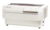
... gap between the platen and printhead. DFx-5tW(h Sewka Manual Oparathg Prfncipka 2.1 OVERVIEW OF PRINTER MECHANISM OPERATION This section describes the Model 3C11 printer mechanism and explains how the printer works. A character is the component ...control circuit controIs CR motor driver deceleration. (Refer to Section 1.4.12, Themud Probation.) L1 Carnage mechanism The carriage mechanism moves the printhead in the horizontal direction. LI Auto platen gap adjustment mechanism The printer mechanism has an automatic platen gap adjustment function that actually pMts characters (dot matrix...
... gap between the platen and printhead. DFx-5tW(h Sewka Manual Oparathg Prfncipka 2.1 OVERVIEW OF PRINTER MECHANISM OPERATION This section describes the Model 3C11 printer mechanism and explains how the printer works. A character is the component ...control circuit controIs CR motor driver deceleration. (Refer to Section 1.4.12, Themud Probation.) L1 Carnage mechanism The carriage mechanism moves the printhead in the horizontal direction. LI Auto platen gap adjustment mechanism The printer mechanism has an automatic platen gap adjustment function that actually pMts characters (dot matrix...
Service Manual
Page 52
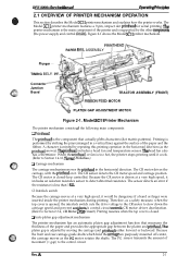
... a different AC power supply, replace the fuse and power cord. O~atfng Princi@aa The power supply board converts the AC voltage to the DC voltages required to operate the printer. l'hree switching regulator circuits convert the AC voltage to the three DC voltages (+35 V, +5 V, ... power to the AC inlet, and is turned off . e m %i;' DFX-5000+ Sendee Mama! The AC voltage is input to three of the nine printhead pins (pins 1,3,5, 7,8, and 9); These switching regulator circuits perform voltage control and over-current limiting for the C117 power supply board assembly depend on .
... a different AC power supply, replace the fuse and power cord. O~atfng Princi@aa The power supply board converts the AC voltage to the DC voltages required to operate the printer. l'hree switching regulator circuits convert the AC voltage to the three DC voltages (+35 V, +5 V, ... power to the AC inlet, and is turned off . e m %i;' DFX-5000+ Sendee Mama! The AC voltage is input to three of the nine printhead pins (pins 1,3,5, 7,8, and 9); These switching regulator circuits perform voltage control and over-current limiting for the C117 power supply board assembly depend on .
Service Manual
Page 53
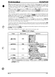
...DFX-5000+ Service Manual 2.2.2 +5 VDC Line Regulator Circuit The +5 VDC line regulator circuit uses a ringing choke coil (RCC) system DC/DC converter. When the power supply board receives this control circuit. One comparator is a common circuit with the DRERR signal feedback circuit on and it cuts off . If the printhead drivers are normal, the control board... output signal is turned on the C117 MAIN board assembly. When the printer is turned on the C117 MAIN board assembly. When the printer is damaged, the control board outputs the error signal (HIGH DRERR signal) to...
...DFX-5000+ Service Manual 2.2.2 +5 VDC Line Regulator Circuit The +5 VDC line regulator circuit uses a ringing choke coil (RCC) system DC/DC converter. When the power supply board receives this control circuit. One comparator is a common circuit with the DRERR signal feedback circuit on and it cuts off . If the printhead drivers are normal, the control board... output signal is turned on the C117 MAIN board assembly. When the printer is turned on the C117 MAIN board assembly. When the printer is damaged, the control board outputs the error signal (HIGH DRERR signal) to...

Service Manual
Page 89
Open the top rover and disconnect connector CN8 (the control panel mnnector). 3. Remove the2 CBB (M4 x 16) screws from the upper case, and then remove the upper case with the Cl17 PNL board assembly and its cable. 0 0 1111111111111 WI 4 CBB ~M4x16) Figure 3-15....front panel and rernovethe panel with the cover open sensor connector) from the C117 MAIN board assembly. 3. A 3-13 Removing the Upper Caae Rev. Removing the Front Panel 3.2.3.4 Removing the Upper Case 1. DFX-5000+ Service Manml Dkassamb(y andAssamb& 3.2.3.3 Removing the Front Panel 1. Disconnect connector CN7 (...
Open the top rover and disconnect connector CN8 (the control panel mnnector). 3. Remove the2 CBB (M4 x 16) screws from the upper case, and then remove the upper case with the Cl17 PNL board assembly and its cable. 0 0 1111111111111 WI 4 CBB ~M4x16) Figure 3-15....front panel and rernovethe panel with the cover open sensor connector) from the C117 MAIN board assembly. 3. A 3-13 Removing the Upper Caae Rev. Removing the Front Panel 3.2.3.4 Removing the Upper Case 1. DFX-5000+ Service Manml Dkassamb(y andAssamb& 3.2.3.3 Removing the Front Panel 1. Disconnect connector CN7 (...

Service Manual
Page 92
... assembly. Slowly return the printer to its back. 5. Since comector CN9 is fixed to protect it from scratches, tilt back the printer and lay it on the C117 MAIN board assembly. While supporting the top cover to the C117 MAIN board assembly, remove the junction ...(Control Panel) CN6 (Mechanism Drive) BOARD ASSY.,C117 MAIN CN1O (DETECTOR, CR) ~CN7 (CASE OPEN SENSOR) CN9 (Inter Lock Switch) CPB (0) (M4x8) (LEFT Side) Figure 3-20. A CPB (M4x16) Figure 3-19. Removing the Bottom Panel Assembly 1 6. Junction Connector (for the bottom panel assembly. Disassembly and Assembly DFX-5000+...
... assembly. Slowly return the printer to its back. 5. Since comector CN9 is fixed to protect it from scratches, tilt back the printer and lay it on the C117 MAIN board assembly. While supporting the top cover to the C117 MAIN board assembly, remove the junction ...(Control Panel) CN6 (Mechanism Drive) BOARD ASSY.,C117 MAIN CN1O (DETECTOR, CR) ~CN7 (CASE OPEN SENSOR) CN9 (Inter Lock Switch) CPB (0) (M4x8) (LEFT Side) Figure 3-20. A CPB (M4x16) Figure 3-19. Removing the Bottom Panel Assembly 1 6. Junction Connector (for the bottom panel assembly. Disassembly and Assembly DFX-5000+...

Service Manual
Page 100
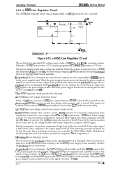
... FEED MOTOR FRAME ,. ,/" " = "'~.' '>. ., 2 CPN (M3x6) k z•• Figure 3-31. On the connector junction board assembly, disconnect the white, 6-pin connector for RF motor control and the yellow, 2-pin connector for the tractor select sensor. 5. Disassembly and Assembly DFX-5000+ Service Manual 3.2.7 Printer Mechanism Disassembly This section describes how to the front/rear tractor select lever...
... FEED MOTOR FRAME ,. ,/" " = "'~.' '>. ., 2 CPN (M3x6) k z•• Figure 3-31. On the connector junction board assembly, disconnect the white, 6-pin connector for RF motor control and the yellow, 2-pin connector for the tractor select sensor. 5. Disassembly and Assembly DFX-5000+ Service Manual 3.2.7 Printer Mechanism Disassembly This section describes how to the front/rear tractor select lever...

Service Manual
Page 135
...drive gear, the maskkws holder will be written to the memory on the C117 Main board in service. After complete this value in this adjustment are as follows: 1) Mechanism....(Refer to perform Step 13 before turn the printer off, and rotate the PG drive gear manually toward you and remove the thickness gauge. Rev. DFX-5000+ Service Manual Adjustment Platen Figure 4-19. ... this adjustment, turn oflthe printer. Be sure to be damaged. Before performing this adjustment is not necessary to correct the printer mechanism parameters which control bidirectional printing. Set the ...
...drive gear, the maskkws holder will be written to the memory on the C117 Main board in service. After complete this value in this adjustment are as follows: 1) Mechanism....(Refer to perform Step 13 before turn the printer off, and rotate the PG drive gear manually toward you and remove the thickness gauge. Rev. DFX-5000+ Service Manual Adjustment Platen Figure 4-19. ... this adjustment, turn oflthe printer. Be sure to be damaged. Before performing this adjustment is not necessary to correct the printer mechanism parameters which control bidirectional printing. Set the ...

Service Manual
Page 136
... the MICRO FEED (v) switch to this, Perform the platen gap value adjustment before perform this time, the printer shifts the standby mode and the no paper state.) 3. Due to shift an even number toward right. ... speed mode. 10. Press the MICRO FEED (A) switch to the front tractor and turn the printer on the Main board. Adjustment DFX-5000+ Service Manual 1. Mount the ribbon cartridge. 2. Set the continuous paper to shift an even... all speed mcdes, press the TOP OF FORM switch. (The printer exhausts the paper and control panel prohibits the all switch operation.) 14.
... the MICRO FEED (v) switch to this, Perform the platen gap value adjustment before perform this time, the printer shifts the standby mode and the no paper state.) 3. Due to shift an even number toward right. ... speed mode. 10. Press the MICRO FEED (A) switch to the front tractor and turn the printer on the Main board. Adjustment DFX-5000+ Service Manual 1. Mount the ribbon cartridge. 2. Set the continuous paper to shift an even... all speed mcdes, press the TOP OF FORM switch. (The printer exhausts the paper and control panel prohibits the all switch operation.) 14.

Service Manual
Page 148
Control panel operation is abnormal. [ START ] Troubleshooting between the C 117 MAIN Yes I Reinsert connector CN8 correctly. 1 I Yes Replace the Cl 17 MAIN board. DFX.5000+ Service Manual 5. Yes v Replace the Cl 17 PNL board. A 5-11 I 4 No v Using a m ultim eter, check the switches on the Cl 17 PNL board. Replace the Cl 17 MAIN board. Rev. Yes v Yes No Replace the Cl 17 PN L board.
Control panel operation is abnormal. [ START ] Troubleshooting between the C 117 MAIN Yes I Reinsert connector CN8 correctly. 1 I Yes Replace the Cl 17 MAIN board. DFX.5000+ Service Manual 5. Yes v Replace the Cl 17 PNL board. A 5-11 I 4 No v Using a m ultim eter, check the switches on the Cl 17 PNL board. Replace the Cl 17 MAIN board. Rev. Yes v Yes No Replace the Cl 17 PN L board.

Service Manual
Page 150
... column. Follow the troubleshooting checks in this symptom. C117 PSB/PSE Board Assembly Main Parts List Location IC151 IC152 (A/B) Q101 Q201 Name TL494 NJM2903 K1 531 K1531 Description PWM switching controller Comparator IC (voltage drop monitor for a list of pins C1-C6...that could produce this column to isolate your problem. Replace the abnormal element. Wait until the printer prints again. Replace the head driver on the main board. DFX-5000+ Service Manual Troubleshooting 5.3 REPAIR OF THE POWER SUPPLY CIRCUIT This section provides detailed troubleshooting methods ...
... column. Follow the troubleshooting checks in this symptom. C117 PSB/PSE Board Assembly Main Parts List Location IC151 IC152 (A/B) Q101 Q201 Name TL494 NJM2903 K1 531 K1531 Description PWM switching controller Comparator IC (voltage drop monitor for a list of pins C1-C6...that could produce this column to isolate your problem. Replace the abnormal element. Wait until the printer prints again. Replace the head driver on the main board. DFX-5000+ Service Manual Troubleshooting 5.3 REPAIR OF THE POWER SUPPLY CIRCUIT This section provides detailed troubleshooting methods ...

Service Manual
Page 173
DFX-5000+ Cable Connections Rev. A A-1 Cl 17 PNL Board Assembly 11 pins 11 pins CN11 CNt 2, Case Open sensor II Interlock Switch CR Motor +35 VDC ON/OFF Cooling Fan ...4pins @ ~~ CNl~ 2 pins 2 pins 22 pins n Cl 17 MAIN Board Assembly ~[ gpifls CN3 CN1 9 pins ~ ~ m g. 2 pins 2 pins 8 pins CN2 = n CN3 8 pins @ CN6 J Serial Interface u Type B Optional Interface ~ Printer Mechanism Control (Control for the motors, printhead, and sensors) 4--J Figure A-1. DFX-5000+ Service Manual Appendix A.1 CONNECTOR SUMMARY FiWre A-1 illustrates the interconnection of the primary...
DFX-5000+ Cable Connections Rev. A A-1 Cl 17 PNL Board Assembly 11 pins 11 pins CN11 CNt 2, Case Open sensor II Interlock Switch CR Motor +35 VDC ON/OFF Cooling Fan ...4pins @ ~~ CNl~ 2 pins 2 pins 22 pins n Cl 17 MAIN Board Assembly ~[ gpifls CN3 CN1 9 pins ~ ~ m g. 2 pins 2 pins 8 pins CN2 = n CN3 8 pins @ CN6 J Serial Interface u Type B Optional Interface ~ Printer Mechanism Control (Control for the motors, printhead, and sensors) 4--J Figure A-1. DFX-5000+ Service Manual Appendix A.1 CONNECTOR SUMMARY FiWre A-1 illustrates the interconnection of the primary...


