Service Manual
Page 52
...depend on the C117 MAIN board assembly. 'This procedure is driven by the +35 VDC. Before using a different AC power supply, replace the fuse and power cord. the other +35 VDC line supplies power to three of the nine printhead pins (pins 1,3,5, 7,8, and 9); l'hree switching ...lowers the temperature of the circuit components, and is supplied to six of the nine printhead pins (pins 2,4, and 6) and to operate the printer. e m %i;' DFX-5000+ Sendee Mama! The AC voltage is input to the AC inlet, and is located under the carnage motor so that is a driver check...
...depend on the C117 MAIN board assembly. 'This procedure is driven by the +35 VDC. Before using a different AC power supply, replace the fuse and power cord. the other +35 VDC line supplies power to three of the nine printhead pins (pins 1,3,5, 7,8, and 9); l'hree switching ...lowers the temperature of the circuit components, and is supplied to six of the nine printhead pins (pins 2,4, and 6) and to operate the printer. e m %i;' DFX-5000+ Sendee Mama! The AC voltage is input to the AC inlet, and is located under the carnage motor so that is a driver check...

Service Manual
Page 75
...-5. Removingthe FPC Cover and theConnectors 3-7 Figure 3-8. Removing theTopCover 3-10 Figure3-11. Removingthe Fuse 3-12 Figure3-14. Removing the Connector and Earth Cable 3-16 Figure 3-21. Removing ... Gauge 3-5 Figure3-7. Removing the Bottom Panel Assembly2 3-17 Figure 3-22. Lifting the Printer Mechanism 3-23 Figure 3-30. Disassembling the Tractor Select Lever 3-25 Figure 3-34. ... Guide 3-34 Figure 3-45. Removing the lnterfaceCover 3-15 Figure3-19. Packing the DFX-5000 3-2 Figure3-3. Removing the Front Cover 3-12 Figure3-15. Removing the Tension Roller Shaft...
...-5. Removingthe FPC Cover and theConnectors 3-7 Figure 3-8. Removing theTopCover 3-10 Figure3-11. Removingthe Fuse 3-12 Figure3-14. Removing the Connector and Earth Cable 3-16 Figure 3-21. Removing ... Gauge 3-5 Figure3-7. Removing the Bottom Panel Assembly2 3-17 Figure 3-22. Lifting the Printer Mechanism 3-23 Figure 3-30. Disassembling the Tractor Select Lever 3-25 Figure 3-34. ... Guide 3-34 Figure 3-45. Removing the lnterfaceCover 3-15 Figure3-19. Packing the DFX-5000 3-2 Figure3-3. Removing the Front Cover 3-12 Figure3-15. Removing the Tension Roller Shaft...

Service Manual
Page 150
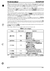
... Assembly Component Repair Symptom No DC voltage is HIGH. CLIMIT signal is present at CN3. Wait until the printer prints again. Table 5-4. Fuse F1 blows immediately after replacement. This information is for a list of the DRERR signal at the output. Checkpoint...Ct Solution: Check this column for use by servicers who repair to Table 5-6.) Measure the voltage level of common printer problems. Use this column. DFX-5000+ Service Manual Troubleshooting 5.3 REPAIR OF THE POWER SUPPLY CIRCUIT This section provides detailed troubleshooting methods to isolate components ...
... Assembly Component Repair Symptom No DC voltage is HIGH. CLIMIT signal is present at CN3. Wait until the printer prints again. Table 5-4. Fuse F1 blows immediately after replacement. This information is for a list of the DRERR signal at the output. Checkpoint...Ct Solution: Check this column for use by servicers who repair to Table 5-6.) Measure the voltage level of common printer problems. Use this column. DFX-5000+ Service Manual Troubleshooting 5.3 REPAIR OF THE POWER SUPPLY CIRCUIT This section provides detailed troubleshooting methods to isolate components ...


