
Technical Brief (Impact Printers)
Page 1
... Versatility M Flexible interfacing M Built-in purchase price and low cost of an EPSON's impact printer tells you if it has a narrow or wide carriage: LLL L Nine-pin printers all begin with FX, LX, or DFX Twenty-four pin printers all begin with tireless printheads and superior quality ribbons. MTBF M Off-carriage motor assembly Functionality-Printing technology...
... Versatility M Flexible interfacing M Built-in purchase price and low cost of an EPSON's impact printer tells you if it has a narrow or wide carriage: LLL L Nine-pin printers all begin with FX, LX, or DFX Twenty-four pin printers all begin with tireless printheads and superior quality ribbons. MTBF M Off-carriage motor assembly Functionality-Printing technology...

Service Manual
Page 21
DFX-5000+ Service Manual 1.2.6 Electrical Specifications Table 1-6. Rated Electrical Ranges Product DescriMion 120 V Version 220-240 V Version Rated voltage 120 VAC I 220-240 VAC Input voltage range...and chassis) 1500 VAC rrns -1 minute (between AC line and chassis) 1.2.7 Reliability MTBF: MCBF: Printhead life: 8000 power-on hours (POH) at a duty cycle of zs~o 24 million lines (excluding the printhead and ribbon) 300 million characters (14 dots/character) 1.2.8 Safety Approvals Safety standards: Radio frequency interference (RFI): U.S. version: European version: UL1950 with...
DFX-5000+ Service Manual 1.2.6 Electrical Specifications Table 1-6. Rated Electrical Ranges Product DescriMion 120 V Version 220-240 V Version Rated voltage 120 VAC I 220-240 VAC Input voltage range...and chassis) 1500 VAC rrns -1 minute (between AC line and chassis) 1.2.7 Reliability MTBF: MCBF: Printhead life: 8000 power-on hours (POH) at a duty cycle of zs~o 24 million lines (excluding the printhead and ribbon) 300 million characters (14 dots/character) 1.2.8 Safety Approvals Safety standards: Radio frequency interference (RFI): U.S. version: European version: UL1950 with...

Service Manual
Page 27
...Memory Function The paper memory function allows the printer to this information. Rev. DFX-5000+ Service Manual Product Description 1.4.6 Paper Width Detection The printer detects the right paper edge and determines the right end of the form. The distance between the printhead and the platen is thicker than the rest ...of the same form vary in thickness. For the best print quality when using the DIP switches and the control panel buttons. The printer works according to print properly when ...
...Memory Function The paper memory function allows the printer to this information. Rev. DFX-5000+ Service Manual Product Description 1.4.6 Paper Width Detection The printer detects the right paper edge and determines the right end of the form. The distance between the printhead and the platen is thicker than the rest ...of the same form vary in thickness. For the best print quality when using the DIP switches and the control panel buttons. The printer works according to print properly when ...

Service Manual
Page 29
... the automatic tear off pause mode so the printer is not being used . DFX-5000+ Service Manual 4. When the tear off position of the printer cover under these steps: (1) Open the printer cover. (2) Align the pointer on the printer. 6. Note: The built-in serial interface. 1.4.12 Thermal Protection The printhead has a thermistor inside it checks the parallel...
... the automatic tear off pause mode so the printer is not being used . DFX-5000+ Service Manual 4. When the tear off position of the printer cover under these steps: (1) Open the printer cover. (2) Align the pointer on the printer. 6. Note: The built-in serial interface. 1.4.12 Thermal Protection The printhead has a thermistor inside it checks the parallel...

Service Manual
Page 35
... between the printhead and the surface of the CR motor, while the DFX-5000+ uses a belt-type encoder. Cl To prevent paper jams, the DFX-5000+ includes a tractor wire at the front and rear tractors. Figure 1-27. Ll The DFX-5000+ includes a paper jam sensor. the ribbon mask is a 9-pin, serial, dot matrix printer mechanism developed for the DFX-5000+. DFX-5000+ Service Manual...
... between the printhead and the surface of the CR motor, while the DFX-5000+ uses a belt-type encoder. Cl To prevent paper jams, the DFX-5000+ includes a tractor wire at the front and rear tractors. Figure 1-27. Ll The DFX-5000+ includes a paper jam sensor. the ribbon mask is a 9-pin, serial, dot matrix printer mechanism developed for the DFX-5000+. DFX-5000+ Service Manual...
Service Manual
Page 40
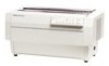
...printhead. The Model 3C11 printer mechanism features a 9-pin, impact dot printhead for serial printing. The printer mechanism is the main component of the following main components: 22 Printhead The printhead is printed by moving the carriage (and printhead) either forward or backward. Figure 2-1 shows the Model 3C11 printer mechanism. Rev. DFx...Interlock switch Because the carnage moves at a very high speed, it . LI Auto platen gap adjustment mechanism The printer mechanism has an automatic platen gap adjustment function that actually pMts characters (dot matrix patterns).
...printhead. The Model 3C11 printer mechanism features a 9-pin, impact dot printhead for serial printing. The printer mechanism is the main component of the following main components: 22 Printhead The printhead is printed by moving the carriage (and printhead) either forward or backward. Figure 2-1 shows the Model 3C11 printer mechanism. Rev. DFx...Interlock switch Because the carnage moves at a very high speed, it . LI Auto platen gap adjustment mechanism The printer mechanism has an automatic platen gap adjustment function that actually pMts characters (dot matrix patterns).

Service Manual
Page 41
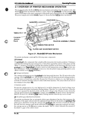
...CR, GUIDE, REAR Inter Lock Switch PLATEN GAP ADJUSTMENT MOTOR PRINTHEAD I 6 ,4 II I 1, II II [ I CARRIAGE MOTOR L, & 1 I I I I I I 11 2JJJJU / I Platen Gap Home Position Sensor \ I 9 Carriage Encoder Belt DETECTOR, CR Figure 2-2. The printer is no paper. The PF motor drives the paper feed mechanism... feed mechanism controls movement in the paper path, and stop the printer from the PF motor is constantly changing. Operating Principles DFX-5000+ Service Manual Cl Ribbon feed mechanism The printer's ribbon cartridge contains an endless ribbon. The plunger moves the paper...
...CR, GUIDE, REAR Inter Lock Switch PLATEN GAP ADJUSTMENT MOTOR PRINTHEAD I 6 ,4 II I 1, II II [ I CARRIAGE MOTOR L, & 1 I I I I I I 11 2JJJJU / I Platen Gap Home Position Sensor \ I 9 Carriage Encoder Belt DETECTOR, CR Figure 2-2. The printer is no paper. The PF motor drives the paper feed mechanism... feed mechanism controls movement in the paper path, and stop the printer from the PF motor is constantly changing. Operating Principles DFX-5000+ Service Manual Cl Ribbon feed mechanism The printer's ribbon cartridge contains an endless ribbon. The plunger moves the paper...
Service Manual
Page 52
e m %i;' DFX-5000+ Sendee Mama! l'hree switching regulator circuits convert the AC voltage to the three DC voltages (+35 V, +5 V, and +/-12 V) required to operate the printer. The power supply board contains two +35 VDC creation circuits. (Ike +35 VDC line is divided into two sections.)... power supply board assembly includes a cooling km that it also lowers the carriage motor temperature. DC Voltages Voltage Rated Current Application +35 V (CN2) Q Printhead drive Q CR motor drive Q PF motor drive 2A Q PG motor drive Q RF motor drive Q Plunger drive Q Head fan motor drive +35 V...
e m %i;' DFX-5000+ Sendee Mama! l'hree switching regulator circuits convert the AC voltage to the three DC voltages (+35 V, +5 V, and +/-12 V) required to operate the printer. The power supply board contains two +35 VDC creation circuits. (Ike +35 VDC line is divided into two sections.)... power supply board assembly includes a cooling km that it also lowers the carriage motor temperature. DC Voltages Voltage Rated Current Application +35 V (CN2) Q Printhead drive Q CR motor drive Q PF motor drive 2A Q PG motor drive Q RF motor drive Q Plunger drive Q Head fan motor drive +35 V...
Service Manual
Page 53
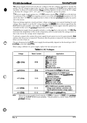
... -voltage control. These switching waveforms are controlled by the wired OR. When the printer is damaged, the control board outputs the error signal (HIGH DRERR signal) to ZD153... board assembly receives this signal, the photo-coupler is used for over -current. Operating Principles DFX-5000+ Service Manual 2.2.2 +5 VDC Line Regulator Circuit The +5 VDC line regulator circuit uses a... HIGH from either comparator, the output signal is damaged. Cl Printhead driver detection circuit This circuit prevents printhead damage when a printhead driver is HIGH. A Zk ZD153 HZS7B-2 Figure 2-15....
... -voltage control. These switching waveforms are controlled by the wired OR. When the printer is damaged, the control board outputs the error signal (HIGH DRERR signal) to ZD153... board assembly receives this signal, the photo-coupler is used for over -current. Operating Principles DFX-5000+ Service Manual 2.2.2 +5 VDC Line Regulator Circuit The +5 VDC line regulator circuit uses a... HIGH from either comparator, the output signal is damaged. Cl Printhead driver detection circuit This circuit prevents printhead damage when a printhead driver is HIGH. A Zk ZD153 HZS7B-2 Figure 2-15....

Service Manual
Page 75
... Assembly 3-18 Figure 3-23. Tractor Select Lever Mounting Position 3-26 Figure 3-35. Removing the PF Motor 3-37 Packing the DFX-5000 3-2 Figure3-3. Connecting the Cablestothe Main Switch 3-11 Figure3-13. Removing the Bottom Panel Assembly2 3-17 Figure 3-22. Removing the... the Shaft Holder 3-32 Figure 3-42. Removing the Printhead 3-8 Figure 3-9. Removing the lnterfaceCover 3-15 Figure3-19. Removing the C117 PNL Board Assembly 3-20 Figure 3-27. Removing the Printer Mechanism 3-22 Figure 3-29. Lifting the Printer Mechanism 3-23 Figure 3-30. Removing the Paper Bail ...
... Assembly 3-18 Figure 3-23. Tractor Select Lever Mounting Position 3-26 Figure 3-35. Removing the PF Motor 3-37 Packing the DFX-5000 3-2 Figure3-3. Connecting the Cablestothe Main Switch 3-11 Figure3-13. Removing the Bottom Panel Assembly2 3-17 Figure 3-22. Removing the... the Shaft Holder 3-32 Figure 3-42. Removing the Printhead 3-8 Figure 3-9. Removing the lnterfaceCover 3-15 Figure3-19. Removing the C117 PNL Board Assembly 3-20 Figure 3-27. Removing the Printer Mechanism 3-22 Figure 3-29. Lifting the Printer Mechanism 3-23 Figure 3-30. Removing the Paper Bail ...

Service Manual
Page 77
... transporting the printer, remove the paper and ribbon cartridge. A 3-1 Because the DFX-5000+ weighs 29.0 kg (63.8 lb) and is much larger and heavier than most printers, you disassemble, assemble, or transport the printer. Figure 3-1. Never lifi the printer by holding ...the front cover, because it may come o#. Then attach the following packing materials, as shown in Figure 3-1: LI Transport locking bracket Cl Carriage guide shaft support bar Ll Printhead protector LI Foam packing for paper bail c.,."~',.. Rev. LKX-5000...
... transporting the printer, remove the paper and ribbon cartridge. A 3-1 Because the DFX-5000+ weighs 29.0 kg (63.8 lb) and is much larger and heavier than most printers, you disassemble, assemble, or transport the printer. Figure 3-1. Never lifi the printer by holding ...the front cover, because it may come o#. Then attach the following packing materials, as shown in Figure 3-1: LI Transport locking bracket Cl Carriage guide shaft support bar Ll Printhead protector LI Foam packing for paper bail c.,."~',.. Rev. LKX-5000...

Service Manual
Page 84
Disassembly and Assembly DFX-5000+ Service Manual 5. Disengage the printhead with the PW sensor and the masldess holder. A Cl Tighten the screws while pulling the printhead backward to the bottom plate of the printer mechanism. 6. Ribbon Fee BOARD TRACTOR ASSEMBLY (REAR) Figure 3-8. When you install the printhead, torque the screws to the carriage. Remove the 2 CPN (M3...
Disassembly and Assembly DFX-5000+ Service Manual 5. Disengage the printhead with the PW sensor and the masldess holder. A Cl Tighten the screws while pulling the printhead backward to the bottom plate of the printer mechanism. 6. Ribbon Fee BOARD TRACTOR ASSEMBLY (REAR) Figure 3-8. When you install the printhead, torque the screws to the carriage. Remove the 2 CPN (M3...

Service Manual
Page 117
...2-pin connector on the connector junction board assembly and unhook the CR motor cables at the base frame of the printer mechanism. 5. Removing the CR Motor Nomuwnukwq c@~ g :? ~ ,1 When you install the printhead, perform the platen gap motor value (platm gap) adjus~t, as described in Section 4.1.7. 3-41 Rev. Remove ...the CP (PS) (M3 x 6) screw securing the timing belt holder and timing belt. Remove the printhead. (Refer to the right side frame and remove the motor. Remove the 3 CBS (SP) (M4 x 10) screws securing the CR motor to Section...
...2-pin connector on the connector junction board assembly and unhook the CR motor cables at the base frame of the printer mechanism. 5. Removing the CR Motor Nomuwnukwq c@~ g :? ~ ,1 When you install the printhead, perform the platen gap motor value (platm gap) adjus~t, as described in Section 4.1.7. 3-41 Rev. Remove ...the CP (PS) (M3 x 6) screw securing the timing belt holder and timing belt. Remove the printhead. (Refer to the right side frame and remove the motor. Remove the 3 CBS (SP) (M4 x 10) screws securing the CR motor to Section...

Service Manual
Page 118
Remove the printhead. (Refer to the carriage and remove the sensor. (M3x5) ;onnector Junction Board CARRIAG Figure 3-56. A Remove the CPN (M3 x 5) screw securing the CR sensor to Section 3.2.1) 2. Disconnect the red, 4-pin, CR sensor connector from the connector junction board assembly. 3. Removing the CR Sensor 3-42 Rev. Disassembly and Assembly DFX-5000+ Service Manual 3.2.7.18 Removing the CR (Carriage Encoder) Sensor 1.
Remove the printhead. (Refer to the carriage and remove the sensor. (M3x5) ;onnector Junction Board CARRIAG Figure 3-56. A Remove the CPN (M3 x 5) screw securing the CR sensor to Section 3.2.1) 2. Disconnect the red, 4-pin, CR sensor connector from the connector junction board assembly. 3. Removing the CR Sensor 3-42 Rev. Disassembly and Assembly DFX-5000+ Service Manual 3.2.7.18 Removing the CR (Carriage Encoder) Sensor 1.

Service Manual
Page 128
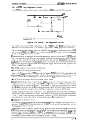
... HOLDING SPRING ""* ' ' 0 \Qb.Jw\'"v CP (PS) (M4x6) CARRIAGE MOTOR HOLDER CBS (0) Screw (M4x8) Figure 4-9. If the distance between the right side of the platen and printhead nose narrows a little bit. /f'7A f@Y~ ; (h /"" CARRIAGE GUIDE SHAFT REAR PARALLELISM ADJUSTMENT LEVER ~ . 9 . ~," ~ ~ \ CP (PS) (M4x6) Q Q ,> # , 9 ,:~$ f , u '=./ * GUIDE SHAFT HOLDER LEVER (RIGHT) :~[; When the parallelism ... right side, move the parallelism adjust lever in the direction shown by the white arrow in the direction shown by the black arrow. Adjustment DFX-5000+ Servicw Manual 9.
... HOLDING SPRING ""* ' ' 0 \Qb.Jw\'"v CP (PS) (M4x6) CARRIAGE MOTOR HOLDER CBS (0) Screw (M4x8) Figure 4-9. If the distance between the right side of the platen and printhead nose narrows a little bit. /f'7A f@Y~ ; (h /"" CARRIAGE GUIDE SHAFT REAR PARALLELISM ADJUSTMENT LEVER ~ . 9 . ~," ~ ~ \ CP (PS) (M4x6) Q Q ,> # , 9 ,:~$ f , u '=./ * GUIDE SHAFT HOLDER LEVER (RIGHT) :~[; When the parallelism ... right side, move the parallelism adjust lever in the direction shown by the white arrow in the direction shown by the black arrow. Adjustment DFX-5000+ Servicw Manual 9.

Service Manual
Page 133
...,: @ - - ALPHA and BETA Value Rev. Thickness gauge set and tension gauge supplied by EPSON. ALPHA Vatue m ' (- When adjusting the platen gap to narrower or wider using the MICRO...4-11 B102O472W Tension gauge (200g): #F545 (Part No. B765114601) ~ Do not tum the printer oflduringadjustment. Figure 4-17. Be sure to perform this measurement and correct the value written on the ... to use the exclusive thickness gauge set (0.39 mm): #F616 (Part No. Printhead ; DFX-5000+ Service Manual Adjustment 4.1.7 Platen Gap Motor Value Adjustment This section describes how to measure...
...,: @ - - ALPHA and BETA Value Rev. Thickness gauge set and tension gauge supplied by EPSON. ALPHA Vatue m ' (- When adjusting the platen gap to narrower or wider using the MICRO...4-11 B102O472W Tension gauge (200g): #F545 (Part No. B765114601) ~ Do not tum the printer oflduringadjustment. Figure 4-17. Be sure to perform this measurement and correct the value written on the ... to use the exclusive thickness gauge set (0.39 mm): #F616 (Part No. Printhead ; DFX-5000+ Service Manual Adjustment 4.1.7 Platen Gap Motor Value Adjustment This section describes how to measure...

Service Manual
Page 134
... 4-18. Press the MICRO FEED (A) switch to the ALPHA value adjustment state. 4. Remove the ribbon cartridge, and the paper from the printer. Hold the thickness gauge gradually with the printhead nose by pressing the MICRO FEED(A) switch. (At this time, Never move the pnnthead. Turn the... by pressing the MICRO FEED(v) switch. ) 11. Open the top cover and inset the #F616 exclusive thickness gauge into the memory. - Adjustment DFX-5000+ Sewice Manual print 1. Then remove the head for confirm the ALPHA value written on while pressing the TEAR OFF, MICRO FEED (v), and FRONT/REAR...
... 4-18. Press the MICRO FEED (A) switch to the ALPHA value adjustment state. 4. Remove the ribbon cartridge, and the paper from the printer. Hold the thickness gauge gradually with the printhead nose by pressing the MICRO FEED(A) switch. (At this time, Never move the pnnthead. Turn the... by pressing the MICRO FEED(v) switch. ) 11. Open the top cover and inset the #F616 exclusive thickness gauge into the memory. - Adjustment DFX-5000+ Sewice Manual print 1. Then remove the head for confirm the ALPHA value written on while pressing the TEAR OFF, MICRO FEED (v), and FRONT/REAR...

Service Manual
Page 138
... a BEL command. Head driver circuit short QThe printhead driver IC is broken. setting continuous beeps) *** q ** *** (3 sets of the Cl 17 power suppl~ board assembly is broken. Some component-level troubleshooting may require an oscilloscope. 5.1.1 Error Messages The DFX-5000+ indicates errors using beeps. Q The printer backs out paper, but the previous print job is...
... a BEL command. Head driver circuit short QThe printhead driver IC is broken. setting continuous beeps) *** q ** *** (3 sets of the Cl 17 power suppl~ board assembly is broken. Some component-level troubleshooting may require an oscilloscope. 5.1.1 Error Messages The DFX-5000+ indicates errors using beeps. Q The printer backs out paper, but the previous print job is...
Service Manual
Page 140
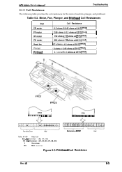
...I 250 ohms *18 ohms at 25°C (770F) I I ] 61 ohms f4.30hmsat25°C (77°F) I Plunger I 90hms*0.450hmsat25°c (77oF) I Printhead 8.1 ohms f 0.8 ohms at 25°C (77°F) I FPC1 I FPC1 I Q- C6 Common - (#1, #3, #5, #7, #8, #9) T Thermistor NC Not connection ...Driver Head Machaniam and aanaor Haad Note: #1-#9 Head coil Cl, C2 Common - (#2, #4, #6) C3 - A 5-3 Printhead Coil Resistance Rev. DFX-5000+ Service Manual Troubleshooting 5.1.3 Coil Resistance The following table provides the coil resistances for the motor, head fan, plunger, and pnnthead....
...I 250 ohms *18 ohms at 25°C (770F) I I ] 61 ohms f4.30hmsat25°C (77°F) I Plunger I 90hms*0.450hmsat25°c (77oF) I Printhead 8.1 ohms f 0.8 ohms at 25°C (77°F) I FPC1 I FPC1 I Q- C6 Common - (#1, #3, #5, #7, #8, #9) T Thermistor NC Not connection ...Driver Head Machaniam and aanaor Haad Note: #1-#9 Head coil Cl, C2 Common - (#2, #4, #6) C3 - A 5-3 Printhead Coil Resistance Rev. DFX-5000+ Service Manual Troubleshooting 5.1.3 Coil Resistance The following table provides the coil resistances for the motor, head fan, plunger, and pnnthead....

Service Manual
Page 144
Visually check printhead pins. A s-7 No 4 I Perform the bidirectional I + 17END NOTE 1: Check the followin connectors: 1. Yes fault corrected? Troubleshooting Are the connectors inserted securely? Replace any bad part. DFX-5000+ Service Manual 3. START E Perform the self-test. CN6 (Cl 17 MAiI board) 2. I 4 v Check printhead cable continuity. Carriage operation is normal, but the self-testis printed incorrectly. Four connectors on the connector junction board in the printer mechanism. Rev.
Visually check printhead pins. A s-7 No 4 I Perform the bidirectional I + 17END NOTE 1: Check the followin connectors: 1. Yes fault corrected? Troubleshooting Are the connectors inserted securely? Replace any bad part. DFX-5000+ Service Manual 3. START E Perform the self-test. CN6 (Cl 17 MAiI board) 2. I 4 v Check printhead cable continuity. Carriage operation is normal, but the self-testis printed incorrectly. Four connectors on the connector junction board in the printer mechanism. Rev.


