Service Manual
Page 40
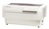
DFx-5tW(h Sewka Manual Oparathg Prfncipka 2.1 OVERVIEW OF PRINTER MECHANISM OPERATION This section describes the Model 3C11 printer mechanism and explains how the printer works. PAPER BA~L ASSEMBLY Plunger TIMING BEL Connector Junction Board TRACTOR ASSEMBLY (FRONT) D MOTOR \ PLATEN GAP ADJUSTMENT MOTOR Figure 2-1. The CR motor drives the carriage, with the printhead on it includes an isolation resistance...
DFx-5tW(h Sewka Manual Oparathg Prfncipka 2.1 OVERVIEW OF PRINTER MECHANISM OPERATION This section describes the Model 3C11 printer mechanism and explains how the printer works. PAPER BA~L ASSEMBLY Plunger TIMING BEL Connector Junction Board TRACTOR ASSEMBLY (FRONT) D MOTOR \ PLATEN GAP ADJUSTMENT MOTOR Figure 2-1. The CR motor drives the carriage, with the printhead on it includes an isolation resistance...

Service Manual
Page 41
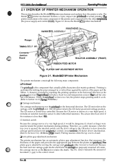
... feed mechanism. By controlling the RF motor, the txactor select mechanism chooses which tractor to move up . Figure 2-3 shows this operation. 2-2 Rev. Operating Principles DFX-5000+ Service Manual Cl Ribbon feed mechanism The printer's ribbon cartridge contains an endless ribbon. Figures 2-2 and 2-3 show the operation of... the ribbon so that the portion hit by the pins is installed. The tractor select sensor detects the selected tractor and signals that it is executed, the paper bail assembly needs to use, and power from the sensors and indicates when an error occurs...
... feed mechanism. By controlling the RF motor, the txactor select mechanism chooses which tractor to move up . Figure 2-3 shows this operation. 2-2 Rev. Operating Principles DFX-5000+ Service Manual Cl Ribbon feed mechanism The printer's ribbon cartridge contains an endless ribbon. Figures 2-2 and 2-3 show the operation of... the ribbon so that the portion hit by the pins is installed. The tractor select sensor detects the selected tractor and signals that it is executed, the paper bail assembly needs to use, and power from the sensors and indicates when an error occurs...

Service Manual
Page 45
...Operation 24 Rev. When paper is absorbed (not reflected). SENSOR ASSY., TRACTOR SENSOR ASSY., PE, UPPER APER BAIL LEVER TIMING BELT, PF ") M- The rotation of the rear tractor assembly gear train and front tractor assembly gear train. (Refer to the upper paper guide and is attached ..., the beam is loaded, the paper surface reflects the beam; The pull tractor sensor monitors whether the pull tractor is loaded, the paper pushes the leaf spring and blocks the photo interrupter. Operating Principles DFX-5000+ Service Manual 2.1.4 Paper Feed Mechanism Figures 2-7, 2-8, and 2-9 show the ...
...Operation 24 Rev. When paper is absorbed (not reflected). SENSOR ASSY., TRACTOR SENSOR ASSY., PE, UPPER APER BAIL LEVER TIMING BELT, PF ") M- The rotation of the rear tractor assembly gear train and front tractor assembly gear train. (Refer to the upper paper guide and is attached ..., the beam is loaded, the paper surface reflects the beam; The pull tractor sensor monitors whether the pull tractor is loaded, the paper pushes the leaf spring and blocks the photo interrupter. Operating Principles DFX-5000+ Service Manual 2.1.4 Paper Feed Mechanism Figures 2-7, 2-8, and 2-9 show the ...

Service Manual
Page 75
...16. Removing the Cl 17 Power Supply Board Assembly 3-18 Figure 3-23. Removing the AC Inlet 3-19 Figure 3-26. Lifting the Printer Mechanism 3-23 Figure 3-30. Removing the Paper Jam Sensor 3-34 Figure 3-46. Packing the DFX-5000 3-2 Figure3-3. Dial Gauge Base 3-4 Figure3-5. RemovingtheBottom...36. Removing the PF Motor 3-37 Removing the Cl 17 MAIN Board Assembly 3-18 Figure 3-24. Connecting the Cables 3-23 Figure 3-31. Removing the Tractor Select Lever2 3-24 Figure 3-33. Tractor Select Lever Mounting Position 3-26 Figure 3-35. Removing the PG Home Sensor...
...16. Removing the Cl 17 Power Supply Board Assembly 3-18 Figure 3-23. Removing the AC Inlet 3-19 Figure 3-26. Lifting the Printer Mechanism 3-23 Figure 3-30. Removing the Paper Jam Sensor 3-34 Figure 3-46. Packing the DFX-5000 3-2 Figure3-3. Dial Gauge Base 3-4 Figure3-5. RemovingtheBottom...36. Removing the PF Motor 3-37 Removing the Cl 17 MAIN Board Assembly 3-18 Figure 3-24. Connecting the Cables 3-23 Figure 3-31. Removing the Tractor Select Lever2 3-24 Figure 3-33. Tractor Select Lever Mounting Position 3-26 Figure 3-35. Removing the PG Home Sensor...

Service Manual
Page 84
Ribbon Fee BOARD TRACTOR ASSEMBLY (REAR) Figure 3-8. Cl Tighten the screws while pulling the printhead backward to the carriage. When you install the printhead, torque the screws to the bottom plate of the printer mechanism. 6. Disengage the printhead with the PW sensor and the masldess holder. A Disassembly and Assembly DFX-5000+ Service Manual 5. Removing the Printhead Q When...
Ribbon Fee BOARD TRACTOR ASSEMBLY (REAR) Figure 3-8. Cl Tighten the screws while pulling the printhead backward to the carriage. When you install the printhead, torque the screws to the bottom plate of the printer mechanism. 6. Disengage the printhead with the PW sensor and the masldess holder. A Disassembly and Assembly DFX-5000+ Service Manual 5. Removing the Printhead Q When...

Service Manual
Page 100
... motor control and the yellow, 2-pin connector for the tractor select sensor. 5. RIBBON FEED GEAR COVER RIBBON FEED / / '-+--'? : // / DRIVE GEAR RIBBON * FEED/=/'I ,,"/.0,,O,'&".j.,% ~~ MOTOR rJ,xf,~ ~ :2,,q.'. , ,-. Before following the steps in Section 3.2.6. 3.2.7.1 Removing the Front/Rear Tractor Select Lever Assembly 1. Disassembly and Assembly DFX-5000+ Service Manual 3.2.7 Printer Mechanism Disassembly This section describes how to the front/rear...
... motor control and the yellow, 2-pin connector for the tractor select sensor. 5. RIBBON FEED GEAR COVER RIBBON FEED / / '-+--'? : // / DRIVE GEAR RIBBON * FEED/=/'I ,,"/.0,,O,'&".j.,% ~~ MOTOR rJ,xf,~ ~ :2,,q.'. , ,-. Before following the steps in Section 3.2.6. 3.2.7.1 Removing the Front/Rear Tractor Select Lever Assembly 1. Disassembly and Assembly DFX-5000+ Service Manual 3.2.7 Printer Mechanism Disassembly This section describes how to the front/rear...

Service Manual
Page 101
... the mm. 4. Remove the CPS (IW2 x 10) screw securing the tractor select sensor and remove the wnsor. Disassembling the Tractor Select Lever 5. DFX-5000+ Service Manual llsassembty and Assamb& 3.2.7.2 Disassembling the Front/Rear Tractor Select Lever Assembly This section describes how to disassemble the front/rear tractor select lever assembly, including how to remove the RF motor and...
... the mm. 4. Remove the CPS (IW2 x 10) screw securing the tractor select sensor and remove the wnsor. Disassembling the Tractor Select Lever 5. DFX-5000+ Service Manual llsassembty and Assamb& 3.2.7.2 Disassembling the Front/Rear Tractor Select Lever Assembly This section describes how to disassemble the front/rear tractor select lever assembly, including how to remove the RF motor and...

Service Manual
Page 102
A RIBBON FEED MOTOR FRAME ~~ \ \ -TRACTOR SELECT CAM TRACTOR SELECT GEAR HOLDER Il I El 1 J / TRACTOR SELECT LEVER (UPPER and LOWER) Figure 3-34. Tractor Select Lever Mounting Position 3-26 Rev. Disassembly and Assembly DFX-5000+ Service Manual T=a-
A RIBBON FEED MOTOR FRAME ~~ \ \ -TRACTOR SELECT CAM TRACTOR SELECT GEAR HOLDER Il I El 1 J / TRACTOR SELECT LEVER (UPPER and LOWER) Figure 3-34. Tractor Select Lever Mounting Position 3-26 Rev. Disassembly and Assembly DFX-5000+ Service Manual T=a-

Service Manual
Page 103
DFX-5000+ SeWica Manual Disassembly and Assembly 3.2.7.3 Removing Connector Junction Board Aasembly and FPC Board Aeaembly This section describes how to the connector junction board assembly, note that the matching connectors have the same color and number of p"ns. ('l%e Appendix provides the connector pin assignments for the CR sensor (encoder) from theconnectorjunction board assembly... board assembly (also died the relaying board) and FPC board assembly. 1. A 3-27 Remove the front/rear tractor select lever assembly. (Refer to the printer mechanism and remove the FPC board assembly. 6,...
DFX-5000+ SeWica Manual Disassembly and Assembly 3.2.7.3 Removing Connector Junction Board Aasembly and FPC Board Aeaembly This section describes how to the connector junction board assembly, note that the matching connectors have the same color and number of p"ns. ('l%e Appendix provides the connector pin assignments for the CR sensor (encoder) from theconnectorjunction board assembly... board assembly (also died the relaying board) and FPC board assembly. 1. A 3-27 Remove the front/rear tractor select lever assembly. (Refer to the printer mechanism and remove the FPC board assembly. 6,...

Service Manual
Page 111
Disconnect the red, 2-pin, pull tractor sensor comector from the connector junction board assembly. 3. Removing the Pull Tractor Sensor 3.2.7.11 Removing the Paper MMth (PW) Sensor 1. o Rev. Remove the CPN (SP) (M2 x 14) screw securing the pull tractor sensor (a micro-switch type sensor) to ... 2. Remove the upper paper guide. (Refer to the left side frame and remove the sensor. Remove theprinthead. (Refer to the masldess holder. PULL TRACTOR 'e PLATEN HOLDER (RIGHT) Hexagon Nut Figure 3-46. Remove the CPN (SP) (M2 x 6) screw securing the PW sensor to [email protected]) ...
Disconnect the red, 2-pin, pull tractor sensor comector from the connector junction board assembly. 3. Removing the Pull Tractor Sensor 3.2.7.11 Removing the Paper MMth (PW) Sensor 1. o Rev. Remove the CPN (SP) (M2 x 14) screw securing the pull tractor sensor (a micro-switch type sensor) to ... 2. Remove the upper paper guide. (Refer to the left side frame and remove the sensor. Remove theprinthead. (Refer to the masldess holder. PULL TRACTOR 'e PLATEN HOLDER (RIGHT) Hexagon Nut Figure 3-46. Remove the CPN (SP) (M2 x 6) screw securing the PW sensor to [email protected]) ...

Service Manual
Page 112
IDE IDE Figure 3-48. Discomect the white, 2-pin, PG home sensor comector from the comector junction board assembly. 4. Removing the PG Home Sensor Removing the Carriage Guide Shaft Gear 3. Detach the hook securing the PG home sensor and remove the ...Remove the E-ring securing the carriage guide shaft gear to Section 3.2.7.2) 2. ACTOR SELECT NSOR -l/'J+ AT- ,-'- 2 pin white MtiTOR Figure 3-49. Disassembly and Assembly DFX-5000+ Service Manual 3.2.7.12 Removing the PG Home Sensor 1. Remove the front/rear tractor select lever assembly. (Refer to the rear carnage guide shaft.
IDE IDE Figure 3-48. Discomect the white, 2-pin, PG home sensor comector from the comector junction board assembly. 4. Removing the PG Home Sensor Removing the Carriage Guide Shaft Gear 3. Detach the hook securing the PG home sensor and remove the ...Remove the E-ring securing the carriage guide shaft gear to Section 3.2.7.2) 2. ACTOR SELECT NSOR -l/'J+ AT- ,-'- 2 pin white MtiTOR Figure 3-49. Disassembly and Assembly DFX-5000+ Service Manual 3.2.7.12 Removing the PG Home Sensor 1. Remove the front/rear tractor select lever assembly. (Refer to the rear carnage guide shaft.

Service Manual
Page 114
Remove the series of gears in the order indicated by the numbers in Figure 3-51. 12 ,, lo-- Remove the connector junction board assembly. (Refer to Section 3.2.7.4) 4. Figure 3-51. A Remove the PG motor. (Refer to Section 3.2.7.3) 3. Removing the Left Side Frame Gears 3-38 Rev. Disassembly and Assembly DFX-5000+ Service Manual 3.2.7.14 Removing the Left Side Frame Gears 1. Remove the front/rear tractor select lever assembly. (Refer to Section 3.2.7.2) 2.
Remove the series of gears in the order indicated by the numbers in Figure 3-51. 12 ,, lo-- Remove the connector junction board assembly. (Refer to Section 3.2.7.4) 4. Figure 3-51. A Remove the PG motor. (Refer to Section 3.2.7.3) 3. Removing the Left Side Frame Gears 3-38 Rev. Disassembly and Assembly DFX-5000+ Service Manual 3.2.7.14 Removing the Left Side Frame Gears 1. Remove the front/rear tractor select lever assembly. (Refer to Section 3.2.7.2) 2.

Service Manual
Page 125
... rear tractor assembly. (Refer to Section 3.2.6) 2. r Sensor Switch Left Side Frame ~ Lever '~~ 14_RearPaper Guide ~ pUII Tractor Sensor I Figure 4-4. When you assemble the pull tractor sensor or rear paper guide, check the following iterns: ~ Verify that the pull tractor sensor lever is touching the rear paper guide frame, but the sensor is incorrect. DFX-5000+ Service Manual Adjustment 4.1.3 Tractor Wire...
... rear tractor assembly. (Refer to Section 3.2.6) 2. r Sensor Switch Left Side Frame ~ Lever '~~ 14_RearPaper Guide ~ pUII Tractor Sensor I Figure 4-4. When you assemble the pull tractor sensor or rear paper guide, check the following iterns: ~ Verify that the pull tractor sensor lever is touching the rear paper guide frame, but the sensor is incorrect. DFX-5000+ Service Manual Adjustment 4.1.3 Tractor Wire...

Service Manual
Page 164
... Solution Check the PWsensor. The paper bail assembly does not work. PerForm the tractor wire spring tension adjustment, as described in Section 4.1.3. Rev. The tractor select gear is defective. Check the coil resistance of the tractor select sensor. A 5-27 Cause The PW sensor is incorrect. Replace the plunger. DFX-5000+ Service Manual Troubleshooting Table 5-7. Visually check...
... Solution Check the PWsensor. The paper bail assembly does not work. PerForm the tractor wire spring tension adjustment, as described in Section 4.1.3. Rev. The tractor select gear is defective. Check the coil resistance of the tractor select sensor. A 5-27 Cause The PW sensor is incorrect. Replace the plunger. DFX-5000+ Service Manual Troubleshooting Table 5-7. Visually check...

Service Manual
Page 177
A A-s DFX-5000+ Service Manual Table A-7. GND Ground for the sensors 17 H17GND Head fan temperature sensor 29,30,31, 52 - NC Not connected Rev. CN6, Cl 17 MAIN Board Assembly Appendix Pin No. 1/0 Name Description 13,21,15, 25,20,23, 0 16,9,18 HDI HD9 Head driver signal ...RF motor phase signal output 3 I HMP Head fan motor temperature detection data input 26 I PWID Paper width detection data input 33 I TR.SEL Pull tractor sensor status data input 51 II I P.TRCT I Pulltractorsensor 32 I PGHOME I I 50 I PJAM r 43 I F.PE PG home sensor detection ...
A A-s DFX-5000+ Service Manual Table A-7. GND Ground for the sensors 17 H17GND Head fan temperature sensor 29,30,31, 52 - NC Not connected Rev. CN6, Cl 17 MAIN Board Assembly Appendix Pin No. 1/0 Name Description 13,21,15, 25,20,23, 0 16,9,18 HDI HD9 Head driver signal ...RF motor phase signal output 3 I HMP Head fan motor temperature detection data input 26 I PWID Paper width detection data input 33 I TR.SEL Pull tractor sensor status data input 51 II I P.TRCT I Pulltractorsensor 32 I PGHOME I I 50 I PJAM r 43 I F.PE PG home sensor detection ...


