
Service Manual
Page 9
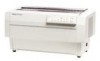
DFX-5000+ Service Manual Product Description 1.1 GENERAL FEATURES The DFX-5000+ is designed for paper thickness - It is a 9-pin, serial, dot matrix printer with the FX-870/1170 and DFX-5000) D 9 character tables in the standard version 21 character tables in the NLSP (National ...Automatic paper path changing Cl Eight-bit parallel interface and RS-232C serial interface standard Cl Epson ESC/P-83 (ESC/P version 83) printer driver (compatible with a maximum speed of the DFX-5000+ 1-1 Automatic interface selection - too cover "'"'"'"" 'NV' control panel poper separator ----,~"p=,...
DFX-5000+ Service Manual Product Description 1.1 GENERAL FEATURES The DFX-5000+ is designed for paper thickness - It is a 9-pin, serial, dot matrix printer with the FX-870/1170 and DFX-5000) D 9 character tables in the standard version 21 character tables in the NLSP (National ...Automatic paper path changing Cl Eight-bit parallel interface and RS-232C serial interface standard Cl Epson ESC/P-83 (ESC/P version 83) printer driver (compatible with a maximum speed of the DFX-5000+ 1-1 Automatic interface selection - too cover "'"'"'"" 'NV' control panel poper separator ----,~"p=,...

Service Manual
Page 10
the printer processes the data from the card. 1-2 Rev. Product Description DFX-5000+ Service Manual Table 1-1. Options and Consumables I I Model Description #8309 Pull tractor unit #8766 Ribbon cartridge t #8767 , Ribbon pack I C82305* I Serial I/Fcard, simple serial interface** (SSi), inch screw I ...
the printer processes the data from the card. 1-2 Rev. Product Description DFX-5000+ Service Manual Table 1-1. Options and Consumables I I Model Description #8309 Pull tractor unit #8766 Ribbon cartridge t #8767 , Ribbon pack I C82305* I Serial I/Fcard, simple serial interface** (SSi), inch screw I ...

Service Manual
Page 11
Figure 1-2. A 1-3 Pin Configuration Dot matrix: Printing direction: Text mode Bit image mode Built-in mm printable Columns (inches) (inches) (inches) 2.12 (0.08) 1.69 (0.07) 1.41 (0.06)...(Unidirectional mode can be selected using the ESC U command.) Unidirectional Draft NLQ Roman NLQ Saris Serif Table 1-2. DFX-5000+ Service Manual 1.2 SPECIFICATIONS This section provides detailed information about the DFX-5000+. 1.2.1 Printer Capabilities Printing method: Serial impact dot matrix Pin configuration: 9 wires Pin diameter: 0.29 mm (0.01 inches) Product Description mm (1/72") o I...
Figure 1-2. A 1-3 Pin Configuration Dot matrix: Printing direction: Text mode Bit image mode Built-in mm printable Columns (inches) (inches) (inches) 2.12 (0.08) 1.69 (0.07) 1.41 (0.06)...(Unidirectional mode can be selected using the ESC U command.) Unidirectional Draft NLQ Roman NLQ Saris Serif Table 1-2. DFX-5000+ Service Manual 1.2 SPECIFICATIONS This section provides detailed information about the DFX-5000+. 1.2.1 Printer Capabilities Printing method: Serial impact dot matrix Pin configuration: 9 wires Pin diameter: 0.29 mm (0.01 inches) Product Description mm (1/72") o I...

Service Manual
Page 19
DFX-5000+ Service Manual Product Description Labels Paper path: Label size (W x H): Bottom carrier: Width Length Total thickness: Label examples: Front only 2%x 15/16 inches 4 x 15/16 inches 4 x 17/16 ... Area for Labels When using labels, do not use the TOF (top of each other.) 8. to avoid a paper jam, it is important not to the printer.) 3. Load label forms only onto the front tractor. Feed label forms only in the reverse direction. (Feeding label forms backward may cause a paper jam, or...
DFX-5000+ Service Manual Product Description Labels Paper path: Label size (W x H): Bottom carrier: Width Length Total thickness: Label examples: Front only 2%x 15/16 inches 4 x 15/16 inches 4 x 17/16 ... Area for Labels When using labels, do not use the TOF (top of each other.) 8. to avoid a paper jam, it is important not to the printer.) 3. Load label forms only onto the front tractor. Feed label forms only in the reverse direction. (Feeding label forms backward may cause a paper jam, or...

Service Manual
Page 23
... V through a 3.3 KQ resistor.) If the signal is LOW when the printer is input (auto LF). I If the signal is LOW when the printer is initialized, DC1/DC3 control is approximately 12 p.s. 0 HIGH indicates the printer cannot accept the next data. 0 HIGH indicates paper out. A 1-15...in the printer. Signal ground. Parallel Interface Signals and Connector Pin Assignments Pin No. I /o' Description 1 STROBE 19 2-9 DATA 1- The pulse width is disabled. *The 1/0 column indicates the direction of this signal. Rev. Pulled up to accept the next data. DFX-5000+ Service Manual Product ...
... V through a 3.3 KQ resistor.) If the signal is LOW when the printer is input (auto LF). I If the signal is LOW when the printer is initialized, DC1/DC3 control is approximately 12 p.s. 0 HIGH indicates the printer cannot accept the next data. 0 HIGH indicates paper out. A 1-15...in the printer. Signal ground. Parallel Interface Signals and Connector Pin Assignments Pin No. I /o' Description 1 STROBE 19 2-9 DATA 1- The pulse width is disabled. *The 1/0 column indicates the direction of this signal. Rev. Pulled up to accept the next data. DFX-5000+ Service Manual Product ...

Service Manual
Page 25
... input buffer. (Turns pause mode on the main board when the printer is not fed backward to the TOF position. Enables top of 10,12, or 17 cpi. If all the paper in pause mode. DFX-5000+ Service Manual 1.4 PRINTER OPERATION This section describes the basic operation of form (TOF) and ...tear off positions. Adjusts the paper position, including the top of the printer. Then, the selected paper from the push tractor of the selected paper...
... input buffer. (Turns pause mode on the main board when the printer is not fed backward to the TOF position. Enables top of 10,12, or 17 cpi. If all the paper in pause mode. DFX-5000+ Service Manual 1.4 PRINTER OPERATION This section describes the basic operation of form (TOF) and ...tear off positions. Adjusts the paper position, including the top of the printer. Then, the selected paper from the push tractor of the selected paper...

Service Manual
Page 27
.... Figure 1-25. Overlapping Multi-part Forms Set the information about the label and overlap areas before printing. DFX-5000+ Service Manual Product Description 1.4.6 Paper Width Detection The printer detects the right paper edge and determines the right end of the form. It allows you to print properly...adjusted to match the paper's thickness and obtain the best print quality. 1.4.8 Paper Memory Function The paper memory function allows the printer to save paper format and thickness information using forms with a label Multi-part forms that overlap slightly where they are not ...
.... Figure 1-25. Overlapping Multi-part Forms Set the information about the label and overlap areas before printing. DFX-5000+ Service Manual Product Description 1.4.6 Paper Width Detection The printer detects the right paper edge and determines the right end of the form. It allows you to print properly...adjusted to match the paper's thickness and obtain the best print quality. 1.4.8 Paper Memory Function The paper memory function allows the printer to save paper format and thickness information using forms with a label Multi-part forms that overlap slightly where they are not ...

Service Manual
Page 29
... on the ribbon mask with a label I ON [ ON 5. A 1-21 Hold down , press the appropriate MICRO FEED button. - If the printer beeps once or twice, the information has been saved correctly in this section again. 1.4.9 Automatic Tear Off Function Use DIP switch 3-8 to print. 1.4....ce that the paper format and thickness information has been saved properly. When the pnnthead or cooling fan is not being used. DFX-5000+ Service Manual 4. Then, if the printer receives more data, it , and the printhead cooling fan also has a thermistor. Rev. Table 1-11. When the tear off...
... on the ribbon mask with a label I ON [ ON 5. A 1-21 Hold down , press the appropriate MICRO FEED button. - If the printer beeps once or twice, the information has been saved correctly in this section again. 1.4.9 Automatic Tear Off Function Use DIP switch 3-8 to print. 1.4....ce that the paper format and thickness information has been saved properly. When the pnnthead or cooling fan is not being used. DFX-5000+ Service Manual 4. Then, if the printer receives more data, it , and the printhead cooling fan also has a thermistor. Rev. Table 1-11. When the tear off...

Service Manual
Page 31
... PC865 PC437 OFF Rev. See Table 1-14. OFF OFF See Table 1-16. After settimz one or more DIP switches, turn on the printer to put your settings into effect. DFX-5000+ Service Manual Product Description 1.5 DIP SWITCH SEITINGS This section describes the functions of zero 2-2 Input buffer 2-3 Automatic LF bv CR 2-4 2-5 Interface 2-6 2-7 2-8 Serial bit rate...
... PC865 PC437 OFF Rev. See Table 1-14. OFF OFF See Table 1-16. After settimz one or more DIP switches, turn on the printer to put your settings into effect. DFX-5000+ Service Manual Product Description 1.5 DIP SWITCH SEITINGS This section describes the functions of zero 2-2 Input buffer 2-3 Automatic LF bv CR 2-4 2-5 Interface 2-6 2-7 2-8 Serial bit rate...

Service Manual
Page 35
...fanfold paper, and an automatic mechanism is a 9-pin, serial, dot matrix printer mechanism developed for the DFX-5000+. Cl In the DFX-5000+, the angle between the DFX-5000+ and the DFX-5000 are: U The DFX-5000+ includes a CR motor isolation resistance sensor. Figure 1-27. LI ...has been changed . U The DFX-5000+ does not include a carriage home position sensor. A 1-27 Ll The DFX-5000+ includes a paper jam sensor. M-3C11 Printer Mechanism Rev. DFX-5000+ Service Manual Product Description 1.6.1 M-3CI 1 Printer Mechanism The M-3C11 printer mechanism is included to provide enhanced ...
...fanfold paper, and an automatic mechanism is a 9-pin, serial, dot matrix printer mechanism developed for the DFX-5000+. Cl In the DFX-5000+, the angle between the DFX-5000+ and the DFX-5000 are: U The DFX-5000+ includes a CR motor isolation resistance sensor. Figure 1-27. LI ...has been changed . U The DFX-5000+ does not include a carriage home position sensor. A 1-27 Ll The DFX-5000+ includes a paper jam sensor. M-3C11 Printer Mechanism Rev. DFX-5000+ Service Manual Product Description 1.6.1 M-3CI 1 Printer Mechanism The M-3C11 printer mechanism is included to provide enhanced ...

Service Manual
Page 36
... supply boards; The printer contains one of your printer's board. ~ T101 Trsnsformr oClol 0101 s r RI F1 c,. ,.. .,4- CC3MPAMTER T201 ~a?ol Ttansforrnsr \ '%3101 Figure 1-29. C117 PSWPSE Board Assembly 1-28 Rev. Product LA9ecriotkn DEX-45000+ Service Manual 1.6.2 Main Control Board... MAIN Board Assembly 1.6.3 Power Supply Circuit (C117 PSB/PSE Board Assembly) The C117 PSB/PSE tmrd assembly power supply circuit supplies the control circuit and printer mechanism drive circuit with power. see Table 2-1 for IWC sptam mwt) I ~íI €•°i ÿI -41, u a ,1 0 o...
... supply boards; The printer contains one of your printer's board. ~ T101 Trsnsformr oClol 0101 s r RI F1 c,. ,.. .,4- CC3MPAMTER T201 ~a?ol Ttansforrnsr \ '%3101 Figure 1-29. C117 PSWPSE Board Assembly 1-28 Rev. Product LA9ecriotkn DEX-45000+ Service Manual 1.6.2 Main Control Board... MAIN Board Assembly 1.6.3 Power Supply Circuit (C117 PSB/PSE Board Assembly) The C117 PSB/PSE tmrd assembly power supply circuit supplies the control circuit and printer mechanism drive circuit with power. see Table 2-1 for IWC sptam mwt) I ~íI €•°i ÿI -41, u a ,1 0 o...

Service Manual
Page 37
C117 PNL Board Assembly 1.6.5 Housing The housing consists of which holds the printer mechanism and circuits. The housing has large openings in the front and rear for the paper entrances and exits. c Figure 1-31. Housing Rev. A 1-29 DFX-5000+ Service Manual Product Description 1.6.4 Control Panel Board (C117 PNL Board Assembly) The C117 PNL board assembly is...
C117 PNL Board Assembly 1.6.5 Housing The housing consists of which holds the printer mechanism and circuits. The housing has large openings in the front and rear for the paper entrances and exits. c Figure 1-31. Housing Rev. A 1-29 DFX-5000+ Service Manual Product Description 1.6.4 Control Panel Board (C117 PNL Board Assembly) The C117 PNL board assembly is...

Service Manual
Page 41
... one at the front tractor and one at the paper bail. Figure 2-3 shows this operation. 2-2 Rev. Operating Principles DFX-5000+ Service Manual Cl Ribbon feed mechanism The printer's ribbon cartridge contains an endless ribbon. When paper is loaded or ejected or when the tear off function is installed. The..., the paper bail assembly needs to move up to prevent a paper jam. Figures 2-2 and 2-3 show the operation of gears. The printer is fed smoothly. D Plunger mechanism During printing, the paper bail assembly holds the paper under tension so that the portion hit by the...
... one at the front tractor and one at the paper bail. Figure 2-3 shows this operation. 2-2 Rev. Operating Principles DFX-5000+ Service Manual Cl Ribbon feed mechanism The printer's ribbon cartridge contains an endless ribbon. When paper is loaded or ejected or when the tear off function is installed. The..., the paper bail assembly needs to move up to prevent a paper jam. Figures 2-2 and 2-3 show the operation of gears. The printer is fed smoothly. D Plunger mechanism During printing, the paper bail assembly holds the paper under tension so that the portion hit by the...

Service Manual
Page 42
...Then, the actuating spring ejects the dot wire fix-ward against the ink ribbcm, printing a dot on the paper. The magnetic force holds back the actuating spring. DEX-4XXW Service Manual Opating Princ@ha Paper TRACTOR ASSY.,... PULL PRINTHEAD SENSOR ASSY., PE, FRONT Front Tractor Sprocket \.fi( SENSOR ASSY., PE, UPPER - A 2-3 It is pulled back (left in the coil. c,.. . '1 :..,'; +35VDCo GNDo / . . . / ---J./ /A :- --- \- Printer...
...Then, the actuating spring ejects the dot wire fix-ward against the ink ribbcm, printing a dot on the paper. The magnetic force holds back the actuating spring. DEX-4XXW Service Manual Opating Princ@ha Paper TRACTOR ASSY.,... PULL PRINTHEAD SENSOR ASSY., PE, FRONT Front Tractor Sprocket \.fi( SENSOR ASSY., PE, UPPER - A 2-3 It is pulled back (left in the coil. c,.. . '1 :..,'; +35VDCo GNDo / . . . / ---J./ /A :- --- \- Printer...

Service Manual
Page 43
... pitched slits and is disordered, the control circuit recognizes the carriage home position. The printer does not have a carriage home position sensor; when it is mounted under the timing belt. The rotation of the frame. A Operating Principles DFX4000+ Service Manual 2.1.2 Carriage Mechanism Figure 2-5 shows the carriage mechanism. When the carriage hits the pad...
... pitched slits and is disordered, the control circuit recognizes the carriage home position. The printer does not have a carriage home position sensor; when it is mounted under the timing belt. The rotation of the frame. A Operating Principles DFX4000+ Service Manual 2.1.2 Carriage Mechanism Figure 2-5 shows the carriage mechanism. When the carriage hits the pad...

Service Manual
Page 47
... the tractor release lever is released. The front left tractor sprocket or rear right tractor sprocket is fixed in the printer becomes bubbled, you can move along the tractor shafts. When the tractor release lever is released, the sprocket can move... 24 Rev. Point B shows the movement range of Front Entrance) nsion Tractor Wire > Tension Spring Figure 2-10. A Operating Principles DFX-5000+ Service Manual 2.1.4.1 Tractor Wire Operation The printer is equipped with a tractor wire (white line) to side along the tractor shafts, but it cannot move along the tractor shafts. ...
... the tractor release lever is released. The front left tractor sprocket or rear right tractor sprocket is fixed in the printer becomes bubbled, you can move along the tractor shafts. When the tractor release lever is released, the sprocket can move... 24 Rev. Point B shows the movement range of Front Entrance) nsion Tractor Wire > Tension Spring Figure 2-10. A Operating Principles DFX-5000+ Service Manual 2.1.4.1 Tractor Wire Operation The printer is equipped with a tractor wire (white line) to side along the tractor shafts, but it cannot move along the tractor shafts. ...

Service Manual
Page 51
...O GP Transfosrmar +3SV Drop rnontor Circuil A \. ~ CLIMIT J signal +3SV Over vdtqa - The power supply board outputs the DC current required to the printer in the same way. Power Supply Board Block Diagram 2-12 Rev. Protection Circuil Figure 2-14. They supply power to drive the control circuits and...: the 120 V C117 PSB board assembly or the 220/240 V PSE C117 board assembly. Table 2-1. Recfifiar - Omratinf7 Principles DEW5000+ Service Manual 2.2 POWER SUPPLY OPERATION The printer can be powered by either of these two boards is in the primary circuitry. Surga-cut -
...O GP Transfosrmar +3SV Drop rnontor Circuil A \. ~ CLIMIT J signal +3SV Over vdtqa - The power supply board outputs the DC current required to the printer in the same way. Power Supply Board Block Diagram 2-12 Rev. Protection Circuil Figure 2-14. They supply power to drive the control circuits and...: the 120 V C117 PSB board assembly or the 220/240 V PSE C117 board assembly. Table 2-1. Recfifiar - Omratinf7 Principles DEW5000+ Service Manual 2.2 POWER SUPPLY OPERATION The printer can be powered by either of these two boards is in the primary circuitry. Surga-cut -
Service Manual
Page 53
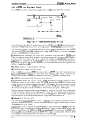
... (+12) monitors the +5 VDC line. This switching procedure monitors the Cl and C2 ports. If the printhead drivers are normal. Operating Principles DFX-5000+ Service Manual 2.2.2 +5 VDC Line Regulator Circuit The +5 VDC line regulator circuit uses a ringing choke coil (RCC) system DC/DC converter. RIM is ...TL494) A C2 cl 1 +11 +12 +35VIX b +3CV,, UI'L.,., )-P PRIMERY CIRCUIT - The power supply board uses a 2-step rise method. When the printer is turned on, the +35 VDC line outputs +13 VDC for 140 ms. The first rising voltage (+13 VDC) is used for over -voltage protection...
... (+12) monitors the +5 VDC line. This switching procedure monitors the Cl and C2 ports. If the printhead drivers are normal. Operating Principles DFX-5000+ Service Manual 2.2.2 +5 VDC Line Regulator Circuit The +5 VDC line regulator circuit uses a ringing choke coil (RCC) system DC/DC converter. RIM is ...TL494) A C2 cl 1 +11 +12 +35VIX b +3CV,, UI'L.,., )-P PRIMERY CIRCUIT - The power supply board uses a 2-step rise method. When the printer is turned on, the +35 VDC line outputs +13 VDC for 140 ms. The first rising voltage (+13 VDC) is used for over -voltage protection...

Service Manual
Page 54
... the C117 MAIN board assembly sends the WC signal, the +35 VDC line rises from +13 V to the wamdary side of the transformer coil. DFX-5000+ Service Manual operating Principbe 2.2.3 +35 VDC Line Regulator Circuit When the printer is turned on the secondary side of T1 and T2 prevent current flow in windings W-4 and '12-3.
... the C117 MAIN board assembly sends the WC signal, the +35 VDC line rises from +13 V to the wamdary side of the transformer coil. DFX-5000+ Service Manual operating Principbe 2.2.3 +35 VDC Line Regulator Circuit When the printer is turned on the secondary side of T1 and T2 prevent current flow in windings W-4 and '12-3.

Service Manual
Page 55
... circuit. o FMer Circuit surge-cut . IC152 monitors the two +35 VDC line creation circuits. Cl +13 VDC creation circuit When the printer is mainly supplied to the base of C157 and R174 makes the delay timing. When this protection circuit; A The CR circuit has approximately ... turned on, the C117 power supply board assembly creates +13 VDC to the C117 power supply board assembly. Operating Principles Dl%Y4iOOO+ Service Manual The +35 VDC regulator circuit includes the following: D Input voltage line over-current protection arcuit (primary side) IC101 and IC201 detect...
... circuit. o FMer Circuit surge-cut . IC152 monitors the two +35 VDC line creation circuits. Cl +13 VDC creation circuit When the printer is mainly supplied to the base of C157 and R174 makes the delay timing. When this protection circuit; A The CR circuit has approximately ... turned on, the C117 power supply board assembly creates +13 VDC to the C117 power supply board assembly. Operating Principles Dl%Y4iOOO+ Service Manual The +35 VDC regulator circuit includes the following: D Input voltage line over-current protection arcuit (primary side) IC101 and IC201 detect...


