
Technical Brief (Impact Printers)
Page 1
... whether it is a registered trademark of Seiko Epson Corporation. 1/00 Other trademarks are capable of an EPSON's impact printer tells you if it has a narrow or wide carriage: LLL L Nine-pin printers all begin with FX, LX, or DFX Twenty-four pin printers all have the sturdiest printhead pins which determines the type of printing and the...
... whether it is a registered trademark of Seiko Epson Corporation. 1/00 Other trademarks are capable of an EPSON's impact printer tells you if it has a narrow or wide carriage: LLL L Nine-pin printers all begin with FX, LX, or DFX Twenty-four pin printers all have the sturdiest printhead pins which determines the type of printing and the...

Service Manual
Page 21
...Physical Specifications Size (W x D x H): Weight: 700 x 382x 369 mm (27.6 x 15.0 x 14.5 inches) 29 kg (63.8 lb) Rev. A 1-13 version: European version: U.S. DFX-5000+ Service Manual 1.2.6 Electrical Specifications Table 1-6. Rated Electrical Ranges Product DescriMion 120 V Version 220-240 V Version Rated voltage 120 VAC I 220-240 VAC Input voltage range... -1 second (between AC line and chassis) 1500 VAC rrns -1 minute (between AC line and chassis) 1.2.7 Reliability MTBF: MCBF: Printhead life: 8000 power-on hours (POH) at a duty cycle of zs~o 24 million lines (excluding the...
...Physical Specifications Size (W x D x H): Weight: 700 x 382x 369 mm (27.6 x 15.0 x 14.5 inches) 29 kg (63.8 lb) Rev. A 1-13 version: European version: U.S. DFX-5000+ Service Manual 1.2.6 Electrical Specifications Table 1-6. Rated Electrical Ranges Product DescriMion 120 V Version 220-240 V Version Rated voltage 120 VAC I 220-240 VAC Input voltage range... -1 second (between AC line and chassis) 1500 VAC rrns -1 minute (between AC line and chassis) 1.2.7 Reliability MTBF: MCBF: Printhead life: 8000 power-on hours (POH) at a duty cycle of zs~o 24 million lines (excluding the...

Service Manual
Page 27
...vary in thickness. Overlapping Multi-part Forms Set the information about the label and overlap areas before printing. DFX-5000+ Service Manual Product Description 1.4.6 Paper Width Detection The printer detects the right paper edge and determines the right end of the form. Note: The tear off ...distance between the printhead and the platen is twice as thick as the rest of the printable area. the overlap area is automatically adjusted to match the paper's thickness and obtain the best print quality. 1.4.8 Paper Memory Function The paper memory function allows the printer to this ...
...vary in thickness. Overlapping Multi-part Forms Set the information about the label and overlap areas before printing. DFX-5000+ Service Manual Product Description 1.4.6 Paper Width Detection The printer detects the right paper edge and determines the right end of the form. Note: The tear off ...distance between the printhead and the platen is twice as thick as the rest of the printable area. the overlap area is automatically adjusted to match the paper's thickness and obtain the best print quality. 1.4.8 Paper Memory Function The paper memory function allows the printer to this ...

Service Manual
Page 29
...ON [ ON 5. Note: The built-in serial interface. 1.4.12 Thermal Protection The printhead has a thermistor inside it, and the printhead cooling fan also has a thermistor. When the pnnthead or cooling fan is detected, the printer beeps, stops feeding the paper, and enters pause mode. Use DIP switches 3-5 ... area 1 or 2. The simple serial interface card takes precedence over the currently selected interface, it cools. Then, if the printer receives more data, it automatically feeds the paper backward to confirm that receives data fit. Rev. DFX-5000+ Service Manual 4.
...ON [ ON 5. Note: The built-in serial interface. 1.4.12 Thermal Protection The printhead has a thermistor inside it, and the printhead cooling fan also has a thermistor. When the pnnthead or cooling fan is detected, the printer beeps, stops feeding the paper, and enters pause mode. Use DIP switches 3-5 ... area 1 or 2. The simple serial interface card takes precedence over the currently selected interface, it cools. Then, if the printer receives more data, it automatically feeds the paper backward to confirm that receives data fit. Rev. DFX-5000+ Service Manual 4.

Service Manual
Page 30
... open is detected: The cover open sensor detects that the cover is open . The interlock switch detects that could scratch the printhead during paper feeding. Sets the horizontal tab position to : - The ESC BEL command (07H) is input. *(1 beep)... A carnage error is detected due to every 8 columns. CRlockup. A paper out or paper jam is detected. (The printer runs out of 2 ~) **** W-* @ *S, A micro adjust limit is detected. "** "w (2 sets of 3 beepa) q 5 sek of 4 beeps) *"* (3 beeps) * **•" (sbeepswi~ a w= ~tween each beep)...
... open is detected: The cover open sensor detects that the cover is open . The interlock switch detects that could scratch the printhead during paper feeding. Sets the horizontal tab position to : - The ESC BEL command (07H) is input. *(1 beep)... A carnage error is detected due to every 8 columns. CRlockup. A paper out or paper jam is detected. (The printer runs out of 2 ~) **** W-* @ *S, A micro adjust limit is detected. "** "w (2 sets of 3 beepa) q 5 sek of 4 beeps) *"* (3 beeps) * **•" (sbeepswi~ a w= ~tween each beep)...

Service Manual
Page 35
... DFX-5000+, the ribbon guide is a 9-pin, serial, dot matrix printer mechanism developed for the DFX-5000+. Figure 1-27. A 1-27 DFX-5000+ Service Manual Product Description 1.6.1 M-3CI 1 Printer Mechanism The M-3C11 printer mechanism is not attached to reduce noise. Cl In the DFX-5000+, the angle between the DFX-5000+ and the DFX-5000 are: U The DFX-5000+ includes a CR motor isolation resistance sensor. The structural differences between the printhead...
... DFX-5000+, the ribbon guide is a 9-pin, serial, dot matrix printer mechanism developed for the DFX-5000+. Figure 1-27. A 1-27 DFX-5000+ Service Manual Product Description 1.6.1 M-3CI 1 Printer Mechanism The M-3C11 printer mechanism is not attached to reduce noise. Cl In the DFX-5000+, the angle between the DFX-5000+ and the DFX-5000 are: U The DFX-5000+ includes a CR motor isolation resistance sensor. The structural differences between the printhead...

Service Manual
Page 36
... one of your printer's board. ~ T101 Trsnsformr oClol 0101 s r RI F1 c,. ,.. .,4- see Table 2-1 for the CR motor, each driver's IC, and the parallel and serial interface control circuits. C117 ... PSB/PSE Board Assembly) The C117 PSB/PSE tmrd assembly power supply circuit supplies the control circuit and printer mechanism drive circuit with power. f o 4- S,22,10,13,16,i4,16,20,21(dnv.r for PRINTHEAD) L Q28 031(dnvor for IWC sptam mwt) I ~íI €•°i ÿI €•CN\3••...
... one of your printer's board. ~ T101 Trsnsformr oClol 0101 s r RI F1 c,. ,.. .,4- see Table 2-1 for the CR motor, each driver's IC, and the parallel and serial interface control circuits. C117 ... PSB/PSE Board Assembly) The C117 PSB/PSE tmrd assembly power supply circuit supplies the control circuit and printer mechanism drive circuit with power. f o 4- S,22,10,13,16,i4,16,20,21(dnv.r for PRINTHEAD) L Q28 031(dnvor for IWC sptam mwt) I ~íI €•°i ÿI €•CN\3••...

Service Manual
Page 38
CHAPTER 2 Operating Principles Table of Contents 2.1 OVERVIEW OF PRINTER MECHANISM OPERATION 2-1 2.1.1 Printhead Mechanism 2-3 2.1.2 Carriage Mechanism 2-4 2.1.3 Platen Gap Adjustment Mechanism 2-5 2.1.4 Paper Feed Mechanism 2-6 2.1.4.1 Tractor Wire Operation 2-8 2.1.5 Ribbon Feed and Tractor Select Mechanism 2-9 2.1.6 Plunger Mechanism 2-11 2.2 POWER SUPPLY ... 2.3.4 CR Motor Driver Cimufi 2-25 2.3.5 PF Motor Driver Cimuit 2-30 2.3.6 RF Motor Driver Circuit 2-31 2.3.7 PG Motor Driver Circuit 2-32 2.3.8 Plunger Driver Circuit 2-33 2.3.9 Printhead Driver Circuit 2-33 c) 62
CHAPTER 2 Operating Principles Table of Contents 2.1 OVERVIEW OF PRINTER MECHANISM OPERATION 2-1 2.1.1 Printhead Mechanism 2-3 2.1.2 Carriage Mechanism 2-4 2.1.3 Platen Gap Adjustment Mechanism 2-5 2.1.4 Paper Feed Mechanism 2-6 2.1.4.1 Tractor Wire Operation 2-8 2.1.5 Ribbon Feed and Tractor Select Mechanism 2-9 2.1.6 Plunger Mechanism 2-11 2.2 POWER SUPPLY ... 2.3.4 CR Motor Driver Cimufi 2-25 2.3.5 PF Motor Driver Cimuit 2-30 2.3.6 RF Motor Driver Circuit 2-31 2.3.7 PG Motor Driver Circuit 2-32 2.3.8 Plunger Driver Circuit 2-33 2.3.9 Printhead Driver Circuit 2-33 c) 62

Service Manual
Page 39
...Deceleration Control Curve 2-28 Figure 2-26. PG Motor Driver Circuit 2-32 Figure 2-30. CR Motor Drive Modes 2-26 Table 2-5. Printer Mechanism Operation 2-2 Figure 2-3. Tension Roller and PF Roller Operation 2-6 Figure 2-8. RearTractorAssembly Operation 2-7 Figure 2-10. TractorSelect Mechanism 2-... Circuit 2-15 Figure 2-17. Reset Circuit Block Diagram 2-21 Figure 2-21. Plunger Driver Circuit 2-33 Figure 2-31. Printhead DriverCircuit 2-34 List of Figures Figure 2-1. PF Motor Specifications 2-31 Table 2-7. Platen GapAdjustment Mechanism 2-5 Figure 2-7. Plunger Mechanism...
...Deceleration Control Curve 2-28 Figure 2-26. PG Motor Driver Circuit 2-32 Figure 2-30. CR Motor Drive Modes 2-26 Table 2-5. Printer Mechanism Operation 2-2 Figure 2-3. Tension Roller and PF Roller Operation 2-6 Figure 2-8. RearTractorAssembly Operation 2-7 Figure 2-10. TractorSelect Mechanism 2-... Circuit 2-15 Figure 2-17. Reset Circuit Block Diagram 2-21 Figure 2-21. Plunger Driver Circuit 2-33 Figure 2-31. Printhead DriverCircuit 2-34 List of Figures Figure 2-1. PF Motor Specifications 2-31 Table 2-7. Platen GapAdjustment Mechanism 2-5 Figure 2-7. Plunger Mechanism...
Service Manual
Page 40
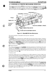
... ADJUSTMENT MOTOR Figure 2-1. Rev. A 2-1 DFx-5tW(h Sewka Manual Oparathg Prfncipka 2.1 OVERVIEW OF PRINTER MECHANISM OPERATION This section describes the Model 3C11 printer mechanism and explains how the printer works. Figure 2-1 shows the Model 3C11 printer mechanism. The CR motor is closed ....dot matrix patterns). A character is performed by repeating this printing operation in a vertical line) against the surface of the printer and is adjusted by the other mmponents (the power supply and control arcuits). The Model 3C11 printer mechanism features a 9-pin, impact dot printhead...
... ADJUSTMENT MOTOR Figure 2-1. Rev. A 2-1 DFx-5tW(h Sewka Manual Oparathg Prfncipka 2.1 OVERVIEW OF PRINTER MECHANISM OPERATION This section describes the Model 3C11 printer mechanism and explains how the printer works. Figure 2-1 shows the Model 3C11 printer mechanism. The CR motor is closed ....dot matrix patterns). A character is performed by repeating this printing operation in a vertical line) against the surface of the printer and is adjusted by the other mmponents (the power supply and control arcuits). The Model 3C11 printer mechanism features a 9-pin, impact dot printhead...

Service Manual
Page 41
... a series of the ribbon feed mechanism. The RF motor drives the ribbon feed mechanism. SHAFT, CR, GUIDE, REAR Inter Lock Switch PLATEN GAP ADJUSTMENT MOTOR PRINTHEAD I 6 ,4 II I 1, II II [ I CARRIAGE MOTOR L, & 1 I I I I I I 11 2JJJJU / I Platen Gap Home Position Sensor \ I 9 Carriage Encoder ... select sensor detects the selected tractor and signals that information to prevent a paper jam. Operating Principles DFX-5000+ Service Manual Cl Ribbon feed mechanism The printer's ribbon cartridge contains an endless ribbon. The front, rear, and top PE sensors detect whether paper...
... a series of the ribbon feed mechanism. The RF motor drives the ribbon feed mechanism. SHAFT, CR, GUIDE, REAR Inter Lock Switch PLATEN GAP ADJUSTMENT MOTOR PRINTHEAD I 6 ,4 II I 1, II II [ I CARRIAGE MOTOR L, & 1 I I I I I I 11 2JJJJU / I Platen Gap Home Position Sensor \ I 9 Carriage Encoder ... select sensor detects the selected tractor and signals that information to prevent a paper jam. Operating Principles DFX-5000+ Service Manual Cl Ribbon feed mechanism The printer's ribbon cartridge contains an endless ribbon. The front, rear, and top PE sensors detect whether paper...

Service Manual
Page 42
... force holds back the actuating spring. Then, the actuating spring ejects the dot wire fix-ward against the ink ribbcm, printing a dot on the paper. LJ \ -+ ///// Iron Core A Head Drive Coil MASK HOLDER (Cutting) PLATEN ASSY. Printer Mechanism Operation 2 2.1.1 Printhead Mechanism The printhead is attached to the actuating spring at point A. c,.. . '1 :..,'; +35VDCo GNDo / . . . / ---J./ /A :- --- \- When current...
... force holds back the actuating spring. Then, the actuating spring ejects the dot wire fix-ward against the ink ribbcm, printing a dot on the paper. LJ \ -+ ///// Iron Core A Head Drive Coil MASK HOLDER (Cutting) PLATEN ASSY. Printer Mechanism Operation 2 2.1.1 Printhead Mechanism The printhead is attached to the actuating spring at point A. c,.. . '1 :..,'; +35VDCo GNDo / . . . / ---J./ /A :- --- \- When current...

Service Manual
Page 43
...gum pad is disordered by this obstacle. Operating Principles DFX4000+ Service Manual 2.1.2 Carriage Mechanism Figure 2-5 shows the carriage mechanism. The printer does not have a carriage home position sensor; The control circuit monitors the CR motor's pulse; The encoder belt has equally pitched...the carnage timing belt through the carriage belt pulleys at the right and left side of the frame. Carriage Mechanism 2-4 Rev. The printhead is mounted on the carriage, which generates pulses. A photo interrupter (encoder) surrounds the encoder belt and converts the carriage movement into...
...gum pad is disordered by this obstacle. Operating Principles DFX4000+ Service Manual 2.1.2 Carriage Mechanism Figure 2-5 shows the carriage mechanism. The printer does not have a carriage home position sensor; The control circuit monitors the CR motor's pulse; The encoder belt has equally pitched...the carnage timing belt through the carriage belt pulleys at the right and left side of the frame. Carriage Mechanism 2-4 Rev. The printhead is mounted on the carriage, which generates pulses. A photo interrupter (encoder) surrounds the encoder belt and converts the carriage movement into...
Service Manual
Page 52
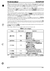
...Down) signal when the printer has exceeded its duty cycle (the printhead temperature is turned off . The specifications for approximately thee minutes after the printer is too high). DC Voltages Voltage Rated Current Application +35 V (CN2) Q Printhead drive Q CR motor .... Table 2-2. A 2-13 The Cl17 power supply board assembly includes a cooling km that it outputs +13 VDC to the printhead drivers on . e m %i;' DFX-5000+ Sendee Mama! Before using a different AC power supply, replace the fuse and power cord. These switching regulator circuits perform voltage...
...Down) signal when the printer has exceeded its duty cycle (the printhead temperature is turned off . The specifications for approximately thee minutes after the printer is too high). DC Voltages Voltage Rated Current Application +35 V (CN2) Q Printhead drive Q CR motor .... Table 2-2. A 2-13 The Cl17 power supply board assembly includes a cooling km that it outputs +13 VDC to the printhead drivers on . e m %i;' DFX-5000+ Sendee Mama! Before using a different AC power supply, replace the fuse and power cord. These switching regulator circuits perform voltage...
Service Manual
Page 53
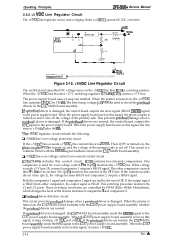
...and comparator 2 outputs a HIGH signal. When the printer is HIGH. If the output signal is HIGH from either comparator, the output signal is turned on and it cuts off . The power supply board uses a 2-step rise method. Operating Principles DFX-5000+ Service Manual 2.2.2 +5 VDC Line Regulator Circuit The...35 VDC line outputs +13 VDC for over -voltage protection circuit If the +5 VDC line exceeds +7 VDC, the current flows to check the printhead drivers on the +5 VDC line first. When the power supply board receives this signal, it creates +35 VDC. 2-14 Rev. This circuit ...
...and comparator 2 outputs a HIGH signal. When the printer is HIGH. If the output signal is HIGH from either comparator, the output signal is turned on and it cuts off . The power supply board uses a 2-step rise method. Operating Principles DFX-5000+ Service Manual 2.2.2 +5 VDC Line Regulator Circuit The...35 VDC line outputs +13 VDC for over -voltage protection circuit If the +5 VDC line exceeds +7 VDC, the current flows to check the printhead drivers on the +5 VDC line first. When the power supply board receives this signal, it creates +35 VDC. 2-14 Rev. This circuit ...

Service Manual
Page 55
...) consisting of the primary circuit. Cl +35 VDC powerdown detection circuit When the +35 VDC line drops (such as, when the printer has exceeded its duty cycle and the printhead temperature is cut Rectifier Smoothing Circuit Circuit C+ Icuit o I I J 4) TF -:== "~ OverCurrent Protection Main switching Circuit (1) Smoothing ...C182 and C181. Cl +13 VDC creation circuit When the printer is operated during the printhead driver check, the power supply board cannot be turned on the standard or optional board and uses the printhead fire trigger. Both the +12 VDC and -12 VDC lines...
...) consisting of the primary circuit. Cl +35 VDC powerdown detection circuit When the +35 VDC line drops (such as, when the printer has exceeded its duty cycle and the printhead temperature is cut Rectifier Smoothing Circuit Circuit C+ Icuit o I I J 4) TF -:== "~ OverCurrent Protection Main switching Circuit (1) Smoothing ...C182 and C181. Cl +13 VDC creation circuit When the printer is operated during the printhead driver check, the power supply board cannot be turned on the standard or optional board and uses the printhead fire trigger. Both the +12 VDC and -12 VDC lines...

Service Manual
Page 56
... off the power supply voltage from an external device (IC8, IC9). The CPU controls all the printer operations via the address bus (MMIO: Memory Mapped Input/Output). Rev. DEX-5000+ Servics Manual @wating *"ncipba 2.3 CONTROL CIRCUIT Figure 2-18 shows a block diagram of the control...directly to store the parameters, such as DRERR, VPC, and CLIMIT (power down), are : ~ (Chip Select) signal creation, address decodina printhead driver control, carriage driver control, encoder pulse arcuit control, PG and c~....\.,., % fan motor phase signal creation, interface control, CR and PF ...
... off the power supply voltage from an external device (IC8, IC9). The CPU controls all the printer operations via the address bus (MMIO: Memory Mapped Input/Output). Rev. DEX-5000+ Servics Manual @wating *"ncipba 2.3 CONTROL CIRCUIT Figure 2-18 shows a block diagram of the control...directly to store the parameters, such as DRERR, VPC, and CLIMIT (power down), are : ~ (Chip Select) signal creation, address decodina printhead driver control, carriage driver control, encoder pulse arcuit control, PG and c~....\.,., % fan motor phase signal creation, interface control, CR and PF ...

Service Manual
Page 57
...) MOTOR,PG P Q17,Q18 PLUNGER I Standard/Optional Interface I 1 BOARD ASSEMBLY, Cl 17 PNL k ZICR A LInterlock itch Q26,22,10,13,16, - 14,18,20,21 I ------+ PRINTHEAD 1 I Each Sensors Circuit I 1 1.PG encorder sensor 2.CR encorder sensor 3. PRINTHEAD thermistor sensor Figure 2-18. A Cover Open 9. Paper Wide 10.Fan Temperature 11 .MOTOR, CR isolation 12.
...) MOTOR,PG P Q17,Q18 PLUNGER I Standard/Optional Interface I 1 BOARD ASSEMBLY, Cl 17 PNL k ZICR A LInterlock itch Q26,22,10,13,16, - 14,18,20,21 I ------+ PRINTHEAD 1 I Each Sensors Circuit I 1 1.PG encorder sensor 2.CR encorder sensor 3. PRINTHEAD thermistor sensor Figure 2-18. A Cover Open 9. Paper Wide 10.Fan Temperature 11 .MOTOR, CR isolation 12.

Service Manual
Page 59
... the CG in the image buffer, it uses the 24-bit shift register in IC7. When the CPU expands the data from the CPU clock) Q Printhead driver control D CR motor driver control LI CR and PG motor pulse encoder l/O (input/output) Q Encoder pulse 1/0 Q Phase signal creation for the motors Q i/O port ...viewed as head data. 7. Note: The data flow from the print data in the download CG). A row of download characters, in the line buffer. the printer performs steps 6 through 8 twice. The print data is always ready to the gate away. The CPU controls the CR motor by byte, accesses the CG...
... the CG in the image buffer, it uses the 24-bit shift register in IC7. When the CPU expands the data from the CPU clock) Q Printhead driver control D CR motor driver control LI CR and PG motor pulse encoder l/O (input/output) Q Encoder pulse 1/0 Q Phase signal creation for the motors Q i/O port ...viewed as head data. 7. Note: The data flow from the print data in the download CG). A row of download characters, in the line buffer. the printer performs steps 6 through 8 twice. The print data is always ready to the gate away. The CPU controls the CR motor by byte, accesses the CG...

Service Manual
Page 72
... this signal, it stops the output voltage and the printer beeps. When switching transistor Q19 is turned on, transistor Q17 is turned off and the hold vottage off off On off off On @> 2.3.9 Printhead Driver Circuit c~' Figure 2-31 shows a printhead driver arcuit block diagram. VP T EOSA87 (IC7) ... lines from suddenly flowing into the plunger coil. DEX-5000+ Servb Manual Dperating Ptinciphs 2.3.8 Plunger Driver Circuit Figure 2-30 shows a block diagram of IC7 goes HIGH, the FETs are turned off and the printhead coil current is cut. The CPU monitors the head temperature...
... this signal, it stops the output voltage and the printer beeps. When switching transistor Q19 is turned on, transistor Q17 is turned off and the hold vottage off off On off off On @> 2.3.9 Printhead Driver Circuit c~' Figure 2-31 shows a printhead driver arcuit block diagram. VP T EOSA87 (IC7) ... lines from suddenly flowing into the plunger coil. DEX-5000+ Servb Manual Dperating Ptinciphs 2.3.8 Plunger Driver Circuit Figure 2-30 shows a block diagram of IC7 goes HIGH, the FETs are turned off and the printhead coil current is cut. The CPU monitors the head temperature...


