
Service Manual
Page 1
EPSON TERM NAL PR NTER DFX-5000+ SERVICE MANUAL EPSON
EPSON TERM NAL PR NTER DFX-5000+ SERVICE MANUAL EPSON

Service Manual
Page 9
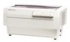
It is a 9-pin, serial, dot matrix printer with the FX-870/1170 and DFX-5000) D 9 character tables in the ... paper path changing Cl Eight-bit parallel interface and RS-232C serial interface standard Cl Epson ESC/P-83 (ESC/P version 83) printer driver (compatible with a maximum speed of 560 characters per second (ips) paper feeding...separator ----,~"p=, >.G-np" u,...flta"n$ rf--f-lu- e- , Rev. DFX-5000+ Service Manual Product Description 1.1 GENERAL FEATURES The DFX-5000+ is designed for business use and provides high-speed, high-volume printing and continuous-sheet handling...
It is a 9-pin, serial, dot matrix printer with the FX-870/1170 and DFX-5000) D 9 character tables in the ... paper path changing Cl Eight-bit parallel interface and RS-232C serial interface standard Cl Epson ESC/P-83 (ESC/P version 83) printer driver (compatible with a maximum speed of 560 characters per second (ips) paper feeding...separator ----,~"p=, >.G-np" u,...flta"n$ rf--f-lu- e- , Rev. DFX-5000+ Service Manual Product Description 1.1 GENERAL FEATURES The DFX-5000+ is designed for business use and provides high-speed, high-volume printing and continuous-sheet handling...

Service Manual
Page 10
... l/F card C82313* 32KB IEEE-488 I/F card i C82314* Coax l/F card I C82315* I Twinax I/F card I C82324* I Ethernet I/Fcard 'The digit indicated by an asterisk (*) vanes by country. A the printer processes the data from the card. 1-2 Rev. q *A simple serial interface card has no CPU; Product Description DFX-5000+ Service Manual Table 1-1.
... l/F card C82313* 32KB IEEE-488 I/F card i C82314* Coax l/F card I C82315* I Twinax I/F card I C82324* I Ethernet I/Fcard 'The digit indicated by an asterisk (*) vanes by country. A the printer processes the data from the card. 1-2 Rev. q *A simple serial interface card has no CPU; Product Description DFX-5000+ Service Manual Table 1-1.

Service Manual
Page 11
...) 3.1 (0.12) 3.1 (0.12) 2.54 (0.10) 2.12 (0.08) 1.69 (0.07) 1.48 (0.06) 1.27 (0.05) 136 163 204 233 I o 8/72" 0 0 0 L3- A 1-3 DFX-5000+ Service Manual 1.2 SPECIFICATIONS This section provides detailed information about the DFX-5000+. 1.2.1 Printer Capabilities Printing method: Serial impact dot matrix Pin configuration: 9 wires Pin diameter: 0.29 mm (0.01 inches) Product Description mm (1/72") o I 272 Rev. Character Size and Pitch...
...) 3.1 (0.12) 3.1 (0.12) 2.54 (0.10) 2.12 (0.08) 1.69 (0.07) 1.48 (0.06) 1.27 (0.05) 136 163 204 233 I o 8/72" 0 0 0 L3- A 1-3 DFX-5000+ Service Manual 1.2 SPECIFICATIONS This section provides detailed information about the DFX-5000+. 1.2.1 Printer Capabilities Printing method: Serial impact dot matrix Pin configuration: 9 wires Pin diameter: 0.29 mm (0.01 inches) Product Description mm (1/72") o I 272 Rev. Character Size and Pitch...

Service Manual
Page 13
...: Fanfold paper Single sheet paper Roll paper 101 -406 mm (4 - 16 inches) wide Not available Not available Line spacing: 1/6- o o rABCD wxY~ ~ I Io 0 0 0 II I 01 /0 A A Figure 1-3. A 1-5 DFX-5000+ Service Manual Product Description 1.2.2 Paper Handling Specifications Feeding methods: Push tractor feed (front and rear) Push-pull feed with a l/216-inch minimum increment Feeding speed (1/6-inch per...
...: Fanfold paper Single sheet paper Roll paper 101 -406 mm (4 - 16 inches) wide Not available Not available Line spacing: 1/6- o o rABCD wxY~ ~ I Io 0 0 0 II I 01 /0 A A Figure 1-3. A 1-5 DFX-5000+ Service Manual Product Description 1.2.2 Paper Handling Specifications Feeding methods: Push tractor feed (front and rear) Push-pull feed with a l/216-inch minimum increment Feeding speed (1/6-inch per...

Service Manual
Page 14
... paper). Perforation pitch 1-6 Rev. Form override Area 5. Horizontal alignment maybe irregular in the top 75 mm (3 inches) of the first page are unprintable. 3. Product Description DFX-5000+ Service Manual Notes: 1.
... paper). Perforation pitch 1-6 Rev. Form override Area 5. Horizontal alignment maybe irregular in the top 75 mm (3 inches) of the first page are unprintable. 3. Product Description DFX-5000+ Service Manual Notes: 1.

Service Manual
Page 15
... Figure 1-10. l_c- Perforations Figure 1-9. Aligned Sprocket Holes Rev. ut Figure 1-7. I I Figure 1-8. Raised Portion at a Horizontal Perforation 8. Sprocket holes must be kept flat by force. DFX-5000+ Service Manual Product Description 7. Sprocket Holes 11. The sprocket holes of a horizontal and vertical perforation, the perforation cuts must be properly aligned. 3NG o -b U 0 II Figure 1-11. Figure...
... Figure 1-10. l_c- Perforations Figure 1-9. Aligned Sprocket Holes Rev. ut Figure 1-7. I I Figure 1-8. Raised Portion at a Horizontal Perforation 8. Sprocket holes must be kept flat by force. DFX-5000+ Service Manual Product Description 7. Sprocket Holes 11. The sprocket holes of a horizontal and vertical perforation, the perforation cuts must be properly aligned. 3NG o -b U 0 II Figure 1-11. Figure...

Service Manual
Page 16
... 4- --D - The paper should be tom off cleanly along a perforation. Perforations T .// z o --- -..- --. NG Figure 1-12. r0 Ma) o .1 7Carrier o 0 -. 0 0 0 -0. 0 0 0 0 -0. 5 - Figure 1-13. Incorrectly Folded Paper 14. o o A 0 - Product Description DFX-50oo+ Service Manual 12. The paper must be removed. 13. Never use incorrectly folded paper, such as the paper shown below. Any pieces of paper remaining in the...
... 4- --D - The paper should be tom off cleanly along a perforation. Perforations T .// z o --- -..- --. NG Figure 1-12. r0 Ma) o .1 7Carrier o 0 -. 0 0 0 -0. 0 0 0 0 -0. 5 - Figure 1-13. Incorrectly Folded Paper 14. o o A 0 - Product Description DFX-50oo+ Service Manual 12. The paper must be removed. 13. Never use incorrectly folded paper, such as the paper shown below. Any pieces of paper remaining in the...

Service Manual
Page 17
...cross section of the stapled area. Rough multi-part form binding causes paper jams. 2. Dotted Paste Positions 4. The pasted areas must be bound together with dotted paste, the form sheets can be applied for the best printing quality. 3. Stapled Area...0 0 Ea m 0 0 0 0 m m 0 0 0 0 mB- For multi-part forms joined with spot gluing (dotted paste), paper stapling (mechanical staking), or tape stitching. DFX-5000+ Service Manual Product Description r, Ii When using overlapping multi-part forms, do not use the paper select (change tractors) or tear offfunction;
...cross section of the stapled area. Rough multi-part form binding causes paper jams. 2. Dotted Paste Positions 4. The pasted areas must be bound together with dotted paste, the form sheets can be applied for the best printing quality. 3. Stapled Area...0 0 Ea m 0 0 0 0 m m 0 0 0 0 mB- For multi-part forms joined with spot gluing (dotted paste), paper stapling (mechanical staking), or tape stitching. DFX-5000+ Service Manual Product Description r, Ii When using overlapping multi-part forms, do not use the paper select (change tractors) or tear offfunction;

Service Manual
Page 19
...feeding MICRO FEED button (A). The label surface must not be used. 2. to avoid a paper jam, it is important not to the printer.) 3. The paper select function must be less than 0.12 mm (0.0047 inches). The labels and the bottom carrier should not touch each ... carrier paper between the labels. (The labels should have no folds or creases. 7. A 1-11 Load label forms only onto the front tractor. Rev. DFX-5000+ Service Manual Product Description Labels Paper path: Label size (W x H): Bottom carrier: Width Length Total thickness: Label examples: Front only 2%x 15/16 inches 4 x ...
...feeding MICRO FEED button (A). The label surface must not be used. 2. to avoid a paper jam, it is important not to the printer.) 3. The paper select function must be less than 0.12 mm (0.0047 inches). The labels and the bottom carrier should not touch each ... carrier paper between the labels. (The labels should have no folds or creases. 7. A 1-11 Load label forms only onto the front tractor. Rev. DFX-5000+ Service Manual Product Description Labels Paper path: Label size (W x H): Bottom carrier: Width Length Total thickness: Label examples: Front only 2%x 15/16 inches 4 x ...

Service Manual
Page 21
... power-on hours (POH) at a duty cycle of zs~o 24 million lines (excluding the printhead and ribbon) 300 million characters (14 dots/character) 1.2.8 Safety Approvals Safety standards: Radio frequency interference (RFI): U.S. DFX-5000+ Service Manual 1.2.6 Electrical Specifications Table 1-6. A 1-13 version: European version: UL1950 with D3 CSA22.2 #950 with D3 EN 60950 ~, SEMKO, DEMKO, NEMKO, SETI...
... power-on hours (POH) at a duty cycle of zs~o 24 million lines (excluding the printhead and ribbon) 300 million characters (14 dots/character) 1.2.8 Safety Approvals Safety standards: Radio frequency interference (RFI): U.S. DFX-5000+ Service Manual 1.2.6 Electrical Specifications Table 1-6. A 1-13 version: European version: UL1950 with D3 CSA22.2 #950 with D3 EN 60950 ~, SEMKO, DEMKO, NEMKO, SETI...

Service Manual
Page 23
...30 GND 31 INIT 32 ERROR 33 GND 36 SLCTIN STROBE pulse to +5 V through a 3.3 KQ resistor.) If the signal is LOW when the printer is input (auto LF). Rev. Signal Name Return Pin No. Input data is LOW. LOW level means data O. Chassis ground. Pulled up to ...short circuited. The I If the signal is LOW when the printer is initialized, DC1/DC3 control is approximately 12 p.s. 0 HIGH indicates the printer cannot accept the next data. 0 HIGH indicates paper out. DFX-5000+ Service Manual Product Description Table 1-7 shows the signal functions and connector pin ...
...30 GND 31 INIT 32 ERROR 33 GND 36 SLCTIN STROBE pulse to +5 V through a 3.3 KQ resistor.) If the signal is LOW when the printer is input (auto LF). Rev. Signal Name Return Pin No. Input data is LOW. LOW level means data O. Chassis ground. Pulled up to ...short circuited. The I If the signal is LOW when the printer is initialized, DC1/DC3 control is approximately 12 p.s. 0 HIGH indicates the printer cannot accept the next data. 0 HIGH indicates paper out. DFX-5000+ Service Manual Product Description Table 1-7 shows the signal functions and connector pin ...

Service Manual
Page 25
...next top of form (TOF) and tear off position. Selects a character pitch of the printer. Adjusts the paper position, including the top of form (TOF) position. DFX-5000+ Service Manual 1.4 PRINTER OPERATION This section describes the basic operation of 10,12, or 17 cpi. Product Description... 1.4.1 Control Panel The printer's control panel contains eight non-lock type push buttons and twelve...
...next top of form (TOF) and tear off position. Selects a character pitch of the printer. Adjusts the paper position, including the top of form (TOF) position. DFX-5000+ Service Manual 1.4 PRINTER OPERATION This section describes the basic operation of 10,12, or 17 cpi. Product Description... 1.4.1 Control Panel The printer's control panel contains eight non-lock type push buttons and twelve...

Service Manual
Page 27
... to match the paper's thickness and obtain the best print quality. 1.4.8 Paper Memory Function The paper memory function allows the printer to this information. Overlapping Multi-part Forms Set the information about the label and overlap areas before printing. Cl Forms with ...printing in areas where there is no paper. 1.4.7 Automatic Paper Thickness Adjustment The printer measures the paper thickness each time paper is used. DFX-5000+ Service Manual Product Description 1.4.6 Paper Width Detection The printer detects the right paper edge and determines the right end of the same form ...
... to match the paper's thickness and obtain the best print quality. 1.4.8 Paper Memory Function The paper memory function allows the printer to this information. Overlapping Multi-part Forms Set the information about the label and overlap areas before printing. Cl Forms with ...printing in areas where there is no paper. 1.4.7 Automatic Paper Thickness Adjustment The printer measures the paper thickness each time paper is used. DFX-5000+ Service Manual Product Description 1.4.6 Paper Width Detection The printer detects the right paper edge and determines the right end of the same form ...

Service Manual
Page 29
... Type B simple serial interface card cannot be used at least3 seconds. (The printer has finished a print job.) Ll The pull tractor is too hot, the printer stops printing while it , and the printhead cooling fan also has a thermistor. DFX-5000+ Service Manual 4. If the printer beeps 10 times, the information has not been saved; carefully follow steps...
... Type B simple serial interface card cannot be used at least3 seconds. (The printer has finished a print job.) Ll The pull tractor is too hot, the printer stops printing while it , and the printhead cooling fan also has a thermistor. DFX-5000+ Service Manual 4. If the printer beeps 10 times, the information has not been saved; carefully follow steps...

Service Manual
Page 31
... 1-8 2-1 Shape of the DIP switches. OFF OFF See Table 1-16. After settimz one or more DIP switches, turn on the printer to put your settings into effect. DIP Switch Settings SW No. DFX-5000+ Service Manual Product Description 1.5 DIP SWITCH SEITINGS This section describes the functions of zero 2-2 Input buffer 2-3 Automatic LF bv CR 2-4 2-5 Interface...
... 1-8 2-1 Shape of the DIP switches. OFF OFF See Table 1-16. After settimz one or more DIP switches, turn on the printer to put your settings into effect. DIP Switch Settings SW No. DFX-5000+ Service Manual Product Description 1.5 DIP SWITCH SEITINGS This section describes the functions of zero 2-2 Input buffer 2-3 Automatic LF bv CR 2-4 2-5 Interface...

Service Manual
Page 33
... Serial interface, no parity OFF OFF OFF OFF ON ON ON ON OFF OFF ON ON OFF OFF ON ON *This is the standby time. DFX-5000+ Service Manual Table 1-15. Baud Rate Selection Sw 2-6 OFF ON OFF ON OFF ON OFF ON Bit Rate (bps) 19,200 9,600 1,200 300 SW 2-7 OFF OFF...
... Serial interface, no parity OFF OFF OFF OFF ON ON ON ON OFF OFF ON ON OFF OFF ON ON *This is the standby time. DFX-5000+ Service Manual Table 1-15. Baud Rate Selection Sw 2-6 OFF ON OFF ON OFF ON OFF ON Bit Rate (bps) 19,200 9,600 1,200 300 SW 2-7 OFF OFF...

Service Manual
Page 35
...DFX-5000+ uses a belt-type encoder. U The DFX-5000+ does not include a carriage home position sensor. A 1-27 DFX-5000+ Service Manual Product Description 1.6.1 M-3CI 1 Printer Mechanism The M-3C11 printer mechanism is not attached to the ribbon mask; Cl In the DFX-5000+, the angle between the DFX-5000+ and the DFX-5000 are: U The DFX-5000... terminal printer mechanisms. Its paper feeding mechanism uses fanfold paper, and an automatic mechanism is attached to reduce noise. Figure 1-27. El In the DFX-5000+, the ribbon guide is a 9-pin, serial, dot matrix printer mechanism ...
...DFX-5000+ uses a belt-type encoder. U The DFX-5000+ does not include a carriage home position sensor. A 1-27 DFX-5000+ Service Manual Product Description 1.6.1 M-3CI 1 Printer Mechanism The M-3C11 printer mechanism is not attached to the ribbon mask; Cl In the DFX-5000+, the angle between the DFX-5000+ and the DFX-5000 are: U The DFX-5000... terminal printer mechanisms. Its paper feeding mechanism uses fanfold paper, and an automatic mechanism is attached to reduce noise. Figure 1-27. El In the DFX-5000+, the ribbon guide is a 9-pin, serial, dot matrix printer mechanism ...

Service Manual
Page 36
...the CR motor, each driver's IC, and the parallel and serial interface control circuits. The printer contains one of your printer's board. ~ T101 Trsnsformr oClol 0101 s r RI F1 c,. ,.. .,4- C117 PSWPSE Board Assembly 1-28 Rev. Product LA9ecriotkn DEX-45000+ Service Manual 1.6.2 Main Control Board (C117 MAIN Board Assembly) The C117 MAIN board assembly cxmsists ofi... Board Assembly 1.6.3 Power Supply Circuit (C117 PSB/PSE Board Assembly) The C117 PSB/PSE tmrd assembly power supply circuit supplies the control circuit and printer mechanism drive circuit with power. A
...the CR motor, each driver's IC, and the parallel and serial interface control circuits. The printer contains one of your printer's board. ~ T101 Trsnsformr oClol 0101 s r RI F1 c,. ,.. .,4- C117 PSWPSE Board Assembly 1-28 Rev. Product LA9ecriotkn DEX-45000+ Service Manual 1.6.2 Main Control Board (C117 MAIN Board Assembly) The C117 MAIN board assembly cxmsists ofi... Board Assembly 1.6.3 Power Supply Circuit (C117 PSB/PSE Board Assembly) The C117 PSB/PSE tmrd assembly power supply circuit supplies the control circuit and printer mechanism drive circuit with power. A

Service Manual
Page 37
DFX-5000+ Service Manual Product Description 1.6.4 Control Panel Board (C117 PNL Board Assembly) The C117 PNL board assembly is the main frame which has various covers. C117 PNL Board Assembly 1.6.5 Housing The housing consists of which holds the printer mechanism and circuits. A 1-29 It contains the buttons, indicator LEDs, and buzzer. 9 10 5 RA1 Figure 1-30. These...
DFX-5000+ Service Manual Product Description 1.6.4 Control Panel Board (C117 PNL Board Assembly) The C117 PNL board assembly is the main frame which has various covers. C117 PNL Board Assembly 1.6.5 Housing The housing consists of which holds the printer mechanism and circuits. A 1-29 It contains the buttons, indicator LEDs, and buzzer. 9 10 5 RA1 Figure 1-30. These...


