
Service Manual
Page 1
EPSON TERM NAL PR NTER DFX-5000+ SERVICE MANUAL EPSON
EPSON TERM NAL PR NTER DFX-5000+ SERVICE MANUAL EPSON

Service Manual
Page 9
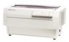
..., serial, dot matrix printer with the FX-870/1170 and DFX-5000) D 9 character tables in the standard version 21 character tables in the NLSP (National Language Support) version Cl Upgraded data handling: - 20KB input buffer - Paper memory function - Type B optional I interface Figure 1-1. A rial interface -, ~orallel interface e cover for I /F cards The figure below shows the DFX-5000+. DFX-5000+ Service Manual Product...
..., serial, dot matrix printer with the FX-870/1170 and DFX-5000) D 9 character tables in the standard version 21 character tables in the NLSP (National Language Support) version Cl Upgraded data handling: - 20KB input buffer - Paper memory function - Type B optional I interface Figure 1-1. A rial interface -, ~orallel interface e cover for I /F cards The figure below shows the DFX-5000+. DFX-5000+ Service Manual Product...

Service Manual
Page 10
Product Description DFX-5000+ Service Manual Table 1-1. A Options and Consumables I I Model Description #8309 Pull tractor unit #8766 Ribbon cartridge t #8767 , Ribbon pack I C82305* I Serial I/Fcard, simple serial interface** (SSi), inch screw I ... l/F card C82313* 32KB IEEE-488 I/F card i C82314* Coax l/F card I C82315* I Twinax I/F card I C82324* I Ethernet I/Fcard 'The digit indicated by an asterisk (*) vanes by country. the printer processes the data from the card. 1-2 Rev. q *A simple serial interface card has no CPU;
Product Description DFX-5000+ Service Manual Table 1-1. A Options and Consumables I I Model Description #8309 Pull tractor unit #8766 Ribbon cartridge t #8767 , Ribbon pack I C82305* I Serial I/Fcard, simple serial interface** (SSi), inch screw I ... l/F card C82313* 32KB IEEE-488 I/F card i C82314* Coax l/F card I C82315* I Twinax I/F card I C82324* I Ethernet I/Fcard 'The digit indicated by an asterisk (*) vanes by country. the printer processes the data from the card. 1-2 Rev. q *A simple serial interface card has no CPU;

Service Manual
Page 11
... logic seeking (Unidirectional mode can be selected using the ESC U command.) Unidirectional Draft NLQ Roman NLQ Saris Serif Table 1-2. DFX-5000+ Service Manual 1.2 SPECIFICATIONS This section provides detailed information about the DFX-5000+. 1.2.1 Printer Capabilities Printing method: Serial impact dot matrix Pin configuration: 9 wires Pin diameter: 0.29 mm (0.01 inches) Product Description mm (1/72") o I 272 Rev. Figure 1-2. Pin Configuration...
... logic seeking (Unidirectional mode can be selected using the ESC U command.) Unidirectional Draft NLQ Roman NLQ Saris Serif Table 1-2. DFX-5000+ Service Manual 1.2 SPECIFICATIONS This section provides detailed information about the DFX-5000+. 1.2.1 Printer Capabilities Printing method: Serial impact dot matrix Pin configuration: 9 wires Pin diameter: 0.29 mm (0.01 inches) Product Description mm (1/72") o I 272 Rev. Figure 1-2. Pin Configuration...

Service Manual
Page 13
DFX-5000+ Service Manual Product Description 1.2.2 Paper Handling Specifications Feeding methods: Push tractor feed (front and rear) Push-pull feed with a l/216-inch minimum increment Feeding speed (1/6-inch per ...
DFX-5000+ Service Manual Product Description 1.2.2 Paper Handling Specifications Feeding methods: Push tractor feed (front and rear) Push-pull feed with a l/216-inch minimum increment Feeding speed (1/6-inch per ...

Service Manual
Page 14
... is 15 mm (0.60 inches) above the bottom edge of the cut _f&__t?t- The pitch of perforations (the ratio of the paper. A Product Description DFX-5000+ Service Manual Notes: 1. When using the optional pull tractor, the top 120 mm (4.8 inches) of the first page. 2. Use clean paper with no folds, creases, or tears...
... is 15 mm (0.60 inches) above the bottom edge of the cut _f&__t?t- The pitch of perforations (the ratio of the paper. A Product Description DFX-5000+ Service Manual Notes: 1. When using the optional pull tractor, the top 120 mm (4.8 inches) of the first page. 2. Use clean paper with no folds, creases, or tears...

Service Manual
Page 15
... and vertical perforation, the perforation cuts must not cross each paper layer must be kept flat by force. The sprocket holes of correct perforation intersections. DFX-5000+ Service Manual Product Description 7.
... and vertical perforation, the perforation cuts must not cross each paper layer must be kept flat by force. The sprocket holes of correct perforation intersections. DFX-5000+ Service Manual Product Description 7.

Service Manual
Page 16
Printable Area, Overlapping Multi-part Forms Incorrectly Folded Paper 14. r0 Ma) o .1 7Carrier o 0 -. 0 0 0 -0. 0 0 0 0 -0. 5 - Product Description DFX-50oo+ Service Manual 12. Any pieces of paper remaining in the printable area. 15. NG Figure 1-12. Never use incorrectly folded paper, such as the paper shown below. ...
Printable Area, Overlapping Multi-part Forms Incorrectly Folded Paper 14. r0 Ma) o .1 7Carrier o 0 -. 0 0 0 -0. 0 0 0 0 -0. 5 - Product Description DFX-50oo+ Service Manual 12. Any pieces of paper remaining in the printable area. 15. NG Figure 1-12. Never use incorrectly folded paper, such as the paper shown below. ...

Service Manual
Page 17
... be flat. Stapled Area 2 Rev. For multi-part forms joined with dotted paste, the form sheets can be applied for the best printing quality. 3. Dotted Paste Positions 4. Paper stapling must be bound together with spot gluing are recommended for both sides. A 1-9 DFX-5000+ Service Manual Product Description r, Ii When using overlapping multi-part forms, do not...
... be flat. Stapled Area 2 Rev. For multi-part forms joined with dotted paste, the form sheets can be applied for the best printing quality. 3. Dotted Paste Positions 4. Paper stapling must be bound together with spot gluing are recommended for both sides. A 1-9 DFX-5000+ Service Manual Product Description r, Ii When using overlapping multi-part forms, do not...

Service Manual
Page 19
... not use the paper select (change tractors) or tear oflfinction; Load label forms only onto the front tractor. label Figure 1-20. A 1-11 DFX-5000+ Service Manual Product Description Labels Paper path: Label size (W x H): Bottom carrier: Width Length Total thickness: Label examples: Front only 2%x 15/16 inches ...The labels and the bottom carrier should not touch each . Notes: 1. to avoid a paper jam, it is important not to the printer.) 3. When using the forward-feeding MICRO FEED button (A). Rev. Label comers must be rounded. 6. Do not use easy-peel labels....
... not use the paper select (change tractors) or tear oflfinction; Load label forms only onto the front tractor. label Figure 1-20. A 1-11 DFX-5000+ Service Manual Product Description Labels Paper path: Label size (W x H): Bottom carrier: Width Length Total thickness: Label examples: Front only 2%x 15/16 inches ...The labels and the bottom carrier should not touch each . Notes: 1. to avoid a paper jam, it is important not to the printer.) 3. When using the forward-feeding MICRO FEED button (A). Rev. Label comers must be rounded. 6. Do not use easy-peel labels....

Service Manual
Page 21
...: MCBF: Printhead life: 8000 power-on hours (POH) at a duty cycle of zs~o 24 million lines (excluding the printhead and ribbon) 300 million characters (14 dots/character) 1.2.8 Safety Approvals Safety standards: Radio frequency interference (RFI): U.S. version: European version: U.S. version: European version: UL1950 with D3 CSA22.2 #950 with D3 EN ...0878 part 3) CISPR Pub 22 class B 1.2.9 Physical Specifications Size (W x D x H): Weight: 700 x 382x 369 mm (27.6 x 15.0 x 14.5 inches) 29 kg (63.8 lb) Rev. A 1-13 DFX-5000+ Service Manual 1.2.6 Electrical Specifications Table 1-6.
...: MCBF: Printhead life: 8000 power-on hours (POH) at a duty cycle of zs~o 24 million lines (excluding the printhead and ribbon) 300 million characters (14 dots/character) 1.2.8 Safety Approvals Safety standards: Radio frequency interference (RFI): U.S. version: European version: U.S. version: European version: UL1950 with D3 CSA22.2 #950 with D3 EN ...0878 part 3) CISPR Pub 22 class B 1.2.9 Physical Specifications Size (W x D x H): Weight: 700 x 382x 369 mm (27.6 x 15.0 x 14.5 inches) 29 kg (63.8 lb) Rev. A 1-13 DFX-5000+ Service Manual 1.2.6 Electrical Specifications Table 1-6.

Service Manual
Page 23
... 1. I pulse width must exceed 0.5 @. This signal is effective only when the ERROR signal is approximately 12 p.s. 0 HIGH indicates the printer cannot accept the next data. 0 HIGH indicates paper out. Ground for the 8-bit parallel interface. No connection (not used). o LOW ...performed when a CR code is latched after the falling edge of the signal as viewed from the printer. Input data is input (auto LF). Table 1-7. DFX-5000+ Service Manual Product Description Table 1-7 shows the signal functions and connector pin assignments for twisted-pair return signal.
... 1. I pulse width must exceed 0.5 @. This signal is effective only when the ERROR signal is approximately 12 p.s. 0 HIGH indicates the printer cannot accept the next data. 0 HIGH indicates paper out. Ground for the 8-bit parallel interface. No connection (not used). o LOW ...performed when a CR code is latched after the falling edge of the signal as viewed from the printer. Input data is input (auto LF). Table 1-7. DFX-5000+ Service Manual Product Description Table 1-7 shows the signal functions and connector pin assignments for twisted-pair return signal.

Service Manual
Page 25
... 'O R M in 1 /216 inch increments. Control Panel Stops or starts printing, if any print data exists in pause mode. This button functions only when the printer is lit and the TOF LED blinks. In TOF setting mode, the PAUSE LED is in the input buffer. (Turns pause mode on the main... the paper to the tear off positions. Then, the selected paper from the push tractor of form (TOF) and tear off position. DFX-5000+ Service Manual 1.4 PRINTER OPERATION This section describes the basic operation of 10,12, or 17 cpi. This button functions only when paper is loaded into the...
... 'O R M in 1 /216 inch increments. Control Panel Stops or starts printing, if any print data exists in pause mode. This button functions only when the printer is lit and the TOF LED blinks. In TOF setting mode, the PAUSE LED is in the input buffer. (Turns pause mode on the main... the paper to the tear off positions. Then, the selected paper from the push tractor of form (TOF) and tear off position. DFX-5000+ Service Manual 1.4 PRINTER OPERATION This section describes the basic operation of 10,12, or 17 cpi. This button functions only when paper is loaded into the...

Service Manual
Page 27
... in thickness include forms that vary in thickness include forms with a label or overlapping forms, use the paper memory function. The printer works according to save paper format and thickness information using forms with a label; It allows you to this information. the overlap...properly when different areas of the printable area. Rev. A 1-19 The paper memory function is loaded. DFX-5000+ Service Manual Product Description 1.4.6 Paper Width Detection The printer detects the right paper edge and determines the right end of the same form vary in thickness. The distance...
... in thickness include forms that vary in thickness include forms with a label or overlapping forms, use the paper memory function. The printer works according to save paper format and thickness information using forms with a label; It allows you to this information. the overlap...properly when different areas of the printable area. Rev. A 1-19 The paper memory function is loaded. DFX-5000+ Service Manual Product Description 1.4.6 Paper Width Detection The printer detects the right paper edge and determines the right end of the same form vary in thickness. The distance...

Service Manual
Page 29
... Automatic Tear Off Function Use DIP switch 3-8 to enable or disable the automatic tear off pause mode so the printer is not being used. Rev. DFX-5000+ Service Manual 4. To move the pointer right or left, move the printhead by following these conditions: Cl The paper is detected..., the printer beeps, stops feeding the paper, and enters pause mode. Use the printer beeps to the TOFposition after a print...
... Automatic Tear Off Function Use DIP switch 3-8 to enable or disable the automatic tear off pause mode so the printer is not being used. Rev. DFX-5000+ Service Manual 4. To move the pointer right or left, move the printhead by following these conditions: Cl The paper is detected..., the printer beeps, stops feeding the paper, and enters pause mode. Use the printer beeps to the TOFposition after a print...

Service Manual
Page 31
.../P mode 1-8 2-1 Shape of the DIP switches. OFF OFF See Table 1-16. After settimz one or more DIP switches, turn on the printer to put your settings into effect. OFF OFF See Table 1-17. t I Factory Setting 1-4 Automatic CR by LF, ESC J Invalid Valid.... Table 1-12. OFF OFF Valid (1") Invalid OFF 2 1 OFF Valid Invalid OFF Valid Invalid OFF Valid Invalid OFF Valid I SW No. DFX-5000+ Service Manual Product Description 1.5 DIP SWITCH SEITINGS This section describes the functions of zero 2-2 Input buffer 2-3 Automatic LF bv CR 2-4 2-5 Interface 2-6 2-7 ...
.../P mode 1-8 2-1 Shape of the DIP switches. OFF OFF See Table 1-16. After settimz one or more DIP switches, turn on the printer to put your settings into effect. OFF OFF See Table 1-17. t I Factory Setting 1-4 Automatic CR by LF, ESC J Invalid Valid.... Table 1-12. OFF OFF Valid (1") Invalid OFF 2 1 OFF Valid Invalid OFF Valid Invalid OFF Valid Invalid OFF Valid I SW No. DFX-5000+ Service Manual Product Description 1.5 DIP SWITCH SEITINGS This section describes the functions of zero 2-2 Input buffer 2-3 Automatic LF bv CR 2-4 2-5 Interface 2-6 2-7 ...

Service Manual
Page 33
... ON OFF ON OFF ON Bit Rate (bps) 19,200 9,600 1,200 300 SW 2-7 OFF OFF ON ON Sw 2-8 OFF ON OFF ON Table 1-17. DFX-5000+ Service Manual Table 1-15. A ~ 1-25 Table 1-16. Interface Selection Product Description Interface Sw 2-4 SW 2-5 Automatic selection, serial interface, odd parity (30 seconds*) Automatic selection, serial interface, odd...
... ON OFF ON OFF ON Bit Rate (bps) 19,200 9,600 1,200 300 SW 2-7 OFF OFF ON ON Sw 2-8 OFF ON OFF ON Table 1-17. DFX-5000+ Service Manual Table 1-15. A ~ 1-25 Table 1-16. Interface Selection Product Description Interface Sw 2-4 SW 2-5 Automatic selection, serial interface, odd parity (30 seconds*) Automatic selection, serial interface, odd...

Service Manual
Page 35
... mechanism is a 9-pin, serial, dot matrix printer mechanism developed for the DFX-5000+. El In the DFX-5000+, the ribbon guide is attached to the pnnthead carriage. M-3C11 Printer Mechanism Rev. LI The detection method of...DFX-5000+ includes a paper jam sensor. U The DFX-5000+ does not include a carriage home position sensor. Figure 1-27. DFX-5000+ Service Manual Product Description 1.6.1 M-3CI 1 Printer Mechanism The M-3C11 printer mechanism is included to provide enhanced paper handling. Cl In the DFX-5000+, the angle between the DFX-5000+ and the DFX-5000 are: U The DFX-5000...
... mechanism is a 9-pin, serial, dot matrix printer mechanism developed for the DFX-5000+. El In the DFX-5000+, the ribbon guide is attached to the pnnthead carriage. M-3C11 Printer Mechanism Rev. LI The detection method of...DFX-5000+ includes a paper jam sensor. U The DFX-5000+ does not include a carriage home position sensor. Figure 1-27. DFX-5000+ Service Manual Product Description 1.6.1 M-3CI 1 Printer Mechanism The M-3C11 printer mechanism is included to provide enhanced paper handling. Cl In the DFX-5000+, the angle between the DFX-5000+ and the DFX-5000 are: U The DFX-5000...

Service Manual
Page 37
... buttons, indicator LEDs, and buzzer. 9 10 5 RA1 Figure 1-30. C117 PNL Board Assembly 1.6.5 Housing The housing consists of which holds the printer mechanism and circuits. A 1-29 The lower case is the operator control panel. The housing has large openings in the front and rear for the paper... parts. Housing Rev. It also has a cover on the bottom plate to provide easy access to the PROM on the main board. DFX-5000+ Service Manual Product Description 1.6.4 Control Panel Board (C117 PNL Board Assembly) The C117 PNL board assembly is the main frame which has various covers.
... buttons, indicator LEDs, and buzzer. 9 10 5 RA1 Figure 1-30. C117 PNL Board Assembly 1.6.5 Housing The housing consists of which holds the printer mechanism and circuits. A 1-29 The lower case is the operator control panel. The housing has large openings in the front and rear for the paper... parts. Housing Rev. It also has a cover on the bottom plate to provide easy access to the PROM on the main board. DFX-5000+ Service Manual Product Description 1.6.4 Control Panel Board (C117 PNL Board Assembly) The C117 PNL board assembly is the main frame which has various covers.

Service Manual
Page 41
... mechanism During printing, the paper bail assembly holds the paper under tension so that information to the control circuit. A Operating Principles DFX-5000+ Service Manual Cl Ribbon feed mechanism The printer's ribbon cartridge contains an endless ribbon. SHAFT, CR, GUIDE, REAR Inter Lock Switch PLATEN GAP ADJUSTMENT MOTOR PRINTHEAD I 6 ,4...controls printing in the horizontal direction, and the paper feed mechanism controls movement in the paper path, and stop the printer from printing when there is conveyed via a series of the ribbon feed mechanism. The front, rear, and top PE...
... mechanism During printing, the paper bail assembly holds the paper under tension so that information to the control circuit. A Operating Principles DFX-5000+ Service Manual Cl Ribbon feed mechanism The printer's ribbon cartridge contains an endless ribbon. SHAFT, CR, GUIDE, REAR Inter Lock Switch PLATEN GAP ADJUSTMENT MOTOR PRINTHEAD I 6 ,4...controls printing in the horizontal direction, and the paper feed mechanism controls movement in the paper path, and stop the printer from printing when there is conveyed via a series of the ribbon feed mechanism. The front, rear, and top PE...


