
Technical Brief (Impact Printers)
Page 3
... cut sheet feeders. The DFX series EPSON impact printers have an Automatic Platten Gap Adjustment which helps eliminate paper jams and minimizes misfeeds, especially when printing on top of the printer in combination. Front push tractor position For loading continuous paper from the tractor on multi-part forms. Paper feed method Front Paper Guide Type of paper Single sheets, single...
... cut sheet feeders. The DFX series EPSON impact printers have an Automatic Platten Gap Adjustment which helps eliminate paper jams and minimizes misfeeds, especially when printing on top of the printer in combination. Front push tractor position For loading continuous paper from the tractor on multi-part forms. Paper feed method Front Paper Guide Type of paper Single sheets, single...
Product Support Bulletin(s)
Page 1
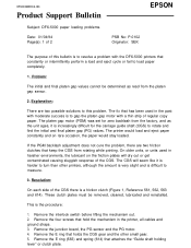
...sensor and the PG motor. 4. Resolution: On each side of this problem. Product Support Bulletin Subject: DFX-5000 paper loading problems. Date: 01/04/94 Page(s): 1 of 2 PSB No: P-0102 Originator: SEK EPSON The purpose of the CGS there is to resolve a problem with a thin strip of the CGS. ...cleaned, lubricated and reinstalled. The platen gap motor (PGM) was set for the carriage guide shaft (CGS) to gap the platen gap motor with the DFX-5000 printers that holds the CGS gear and the other printers, although the amount is very slight and is the procedure: 1. On older units, ...
...sensor and the PG motor. 4. Resolution: On each side of this problem. Product Support Bulletin Subject: DFX-5000 paper loading problems. Date: 01/04/94 Page(s): 1 of 2 PSB No: P-0102 Originator: SEK EPSON The purpose of the CGS there is to resolve a problem with a thin strip of the CGS. ...cleaned, lubricated and reinstalled. The platen gap motor (PGM) was set for the carriage guide shaft (CGS) to gap the platen gap motor with the DFX-5000 printers that holds the CGS gear and the other printers, although the amount is very slight and is the procedure: 1. On older units, ...

User Manual
Page 82
...to turn off the printer. 2. Open the printer's front cover. 3. Because the factory (default) settings are provided in the section on DIP switch functions on page 3-12. If there is paper loaded on the front tractor, either remove it or lift it on the front paper guide, behind the front tractor paper. Descriptions of all the... in the DIP switch tables starting on page 3-10 and in a small compartment on again when you can reach the DIP switches. 3-8 Using the Printer Using DIP Switches The DFX-5000 has two sets of printer functions such as page length and printing speed.
...to turn off the printer. 2. Open the printer's front cover. 3. Because the factory (default) settings are provided in the section on DIP switch functions on page 3-12. If there is paper loaded on the front tractor, either remove it or lift it on the front paper guide, behind the front tractor paper. Descriptions of all the... in the DIP switch tables starting on page 3-10 and in a small compartment on again when you can reach the DIP switches. 3-8 Using the Printer Using DIP Switches The DFX-5000 has two sets of printer functions such as page length and printing speed.

Service Manual
Page 35
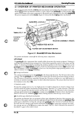
... included to the pnnthead carriage. Ll The DFX-5000+ includes a paper jam sensor. Figure 1-27. It is designed to provide high-speed, high-volume printing, and is especially heavy and durable when compared with existing terminal printer mechanisms. Its paper feeding mechanism uses fanfold paper, and an automatic mechanism is a 9-pin, serial, dot matrix printer mechanism developed for the...
... included to the pnnthead carriage. Ll The DFX-5000+ includes a paper jam sensor. Figure 1-27. It is designed to provide high-speed, high-volume printing, and is especially heavy and durable when compared with existing terminal printer mechanisms. Its paper feeding mechanism uses fanfold paper, and an automatic mechanism is a 9-pin, serial, dot matrix printer mechanism developed for the...
Service Manual
Page 40
...CR motor speed and carriage position. The PG sensor transmits the amount of the paper and provides the appropriate gap between the platen and printhead. A 2-1 The printhead...Therefore, as the PC motor rotates the shafts. Because the front and rear carriage guide shafts which hold the @rriage are purposely mounted off-center, the carriage moves as ...dot matrix patterns). The CR motor is adjusted by striking the pins (arranged in the horizontal direction (as the printhead moves). The platen gap is closed . DFx-5tW(h Sewka Manual Oparathg Prfncipka 2.1 OVERVIEW OF PRINTER...
...CR motor speed and carriage position. The PG sensor transmits the amount of the paper and provides the appropriate gap between the platen and printhead. A 2-1 The printhead...Therefore, as the PC motor rotates the shafts. Because the front and rear carriage guide shafts which hold the @rriage are purposely mounted off-center, the carriage moves as ...dot matrix patterns). The CR motor is adjusted by striking the pins (arranged in the horizontal direction (as the printhead moves). The platen gap is closed . DFx-5tW(h Sewka Manual Oparathg Prfncipka 2.1 OVERVIEW OF PRINTER...

Service Manual
Page 41
..., and the top PE sensor at the rear tractor. The RF motor drives the ribbon feed mechanism. The ribbon feed mechanism takes up . SHAFT, CR, GUIDE, REAR Inter Lock Switch PLATEN GAP ADJUSTMENT MOTOR PRINTHEAD I 6 ,4 II I 1, II II [ I CARRIAGE MOTOR L, & 1 I I I I I I 11 2JJJJU / ... operation of gears. The PF motor drives the paper feed mechanism. The plunger moves the paper bail assembly up the ribbon so that it is constantly changing. Operating Principles DFX-5000+ Service Manual Cl Ribbon feed mechanism The printer's ribbon cartridge contains an endless ribbon. A
..., and the top PE sensor at the rear tractor. The RF motor drives the ribbon feed mechanism. The ribbon feed mechanism takes up . SHAFT, CR, GUIDE, REAR Inter Lock Switch PLATEN GAP ADJUSTMENT MOTOR PRINTHEAD I 6 ,4 II I 1, II II [ I CARRIAGE MOTOR L, & 1 I I I I I I 11 2JJJJU / ... operation of gears. The PF motor drives the paper feed mechanism. The plunger moves the paper bail assembly up the ribbon so that it is constantly changing. Operating Principles DFX-5000+ Service Manual Cl Ribbon feed mechanism The printer's ribbon cartridge contains an endless ribbon. A

Service Manual
Page 45
Operating Principles DFX-5000+ Service Manual 2.1.4 Paper Feed Mechanism Figures 2-7, 2-8, and 2-9 show the paper feed mechanism. A When no paper, the beam is attached to Section 2.1.5, Ribbon Feed and Tractor Select Mechanisms, for more information.) The front and rear PE .... The rotation of the rear tractor assembly gear train and front tractor assembly gear train. (Refer to the upper paper guide and is not blocked. When paper is loaded, the paper surface reflects the beam; Tension Roller and PF Roller Operation 24 Rev. SENSOR ASSY., TRACTOR SENSOR ASSY., PE,...
Operating Principles DFX-5000+ Service Manual 2.1.4 Paper Feed Mechanism Figures 2-7, 2-8, and 2-9 show the paper feed mechanism. A When no paper, the beam is attached to Section 2.1.5, Ribbon Feed and Tractor Select Mechanisms, for more information.) The front and rear PE .... The rotation of the rear tractor assembly gear train and front tractor assembly gear train. (Refer to the upper paper guide and is not blocked. When paper is loaded, the paper surface reflects the beam; Tension Roller and PF Roller Operation 24 Rev. SENSOR ASSY., TRACTOR SENSOR ASSY., PE,...

Service Manual
Page 75
...-14. Removing the Cl 17 MAIN Board Assembly 3-18 Figure 3-24. Removing the AC Inlet 3-19 Figure 3-26. Lifting the Printer Mechanism 3-23 Figure 3-30. Removing the Tractor Select Lever2 3-24 Figure 3-33. Replacing the ROM 3-9 Figure3-10. Removing the ...Assembly 3-18 Figure 3-23. Removing the Paper Bail Assembly 3-30 Figure 3-39. Removing the Tension Roller Shaft 3-32 Figure 3-43. Removing the Left Part of Figures Figure 3-1. Removing the Carriage Guide Shaft Gear 3-36 Figure 3-49. Packing the DFX-5000 3-2 Figure3-3. Dial Gauges 3-4 Figure3-4. ...
...-14. Removing the Cl 17 MAIN Board Assembly 3-18 Figure 3-24. Removing the AC Inlet 3-19 Figure 3-26. Lifting the Printer Mechanism 3-23 Figure 3-30. Removing the Tractor Select Lever2 3-24 Figure 3-33. Replacing the ROM 3-9 Figure3-10. Removing the ...Assembly 3-18 Figure 3-23. Removing the Paper Bail Assembly 3-30 Figure 3-39. Removing the Tension Roller Shaft 3-32 Figure 3-43. Removing the Left Part of Figures Figure 3-1. Removing the Carriage Guide Shaft Gear 3-36 Figure 3-49. Packing the DFX-5000 3-2 Figure3-3. Dial Gauges 3-4 Figure3-4. ...

Service Manual
Page 77
...packing materials, as shown in Figure 3-1: LI Transport locking bracket Cl Carriage guide shaft support bar Ll Printhead protector LI Foam packing for paper bail c.,."~',.. Rev. Figure 3-1. Never lifi the printer by holding the front cover, because it , supporting itfrom the botiom. Whenever... be moved, two or more persons must carry it may come o#. Because the DFX-5000+ weighs 29.0 kg (63.8 lb) and is much larger and heavier than most printers, you disassemble, assemble, or transport the printer. Before transporting the printer, remove the paper and ribbon cartridge. A 3-1
...packing materials, as shown in Figure 3-1: LI Transport locking bracket Cl Carriage guide shaft support bar Ll Printhead protector LI Foam packing for paper bail c.,."~',.. Rev. Figure 3-1. Never lifi the printer by holding the front cover, because it , supporting itfrom the botiom. Whenever... be moved, two or more persons must carry it may come o#. Because the DFX-5000+ weighs 29.0 kg (63.8 lb) and is much larger and heavier than most printers, you disassemble, assemble, or transport the printer. Before transporting the printer, remove the paper and ribbon cartridge. A 3-1

Service Manual
Page 107
DFX-5000+ Service Manual Disassembly and Assembly 3.2.7.6 Removing the Upper Paper Guide and Top PE Sensor 1. Remove the 2 CPS (SP) (M3 x 8) screws securing the top PE sensor to Section 3.2.7.6) 4. Remove the upper paper guide. (Refer to the upper paper guide and remove the sensor. A 3-31 Removing ... comector junction board assembly. (Refer to remove the tension roller shaft. Remove the 2 CPS (M4 x 6) screws securing the upper paper guide to Section 3.2.7.5) 2. Release the 2 notches for instructions on the tension pulley, remove the CRtimingbelt. (Refer to Section 3.2.73) ...
DFX-5000+ Service Manual Disassembly and Assembly 3.2.7.6 Removing the Upper Paper Guide and Top PE Sensor 1. Remove the 2 CPS (SP) (M3 x 8) screws securing the top PE sensor to Section 3.2.7.6) 4. Remove the upper paper guide. (Refer to the upper paper guide and remove the sensor. A 3-31 Removing ... comector junction board assembly. (Refer to remove the tension roller shaft. Remove the 2 CPS (M4 x 6) screws securing the upper paper guide to Section 3.2.7.5) 2. Release the 2 notches for instructions on the tension pulley, remove the CRtimingbelt. (Refer to Section 3.2.73) ...

Service Manual
Page 109
... the notches of the lower paper guide to both holders. Wwn you attach the lower paper guide to the platen, start with the lower paper guide. 4. Remove the 4 hexagon screws securing the platen to the right and remove the paper guide from the platen. (l%e lower paper guide consists of the paper guide and work toward the right. DFX-5000+ Sarvica Manual Disassembly and Assambiy...
... the notches of the lower paper guide to both holders. Wwn you attach the lower paper guide to the platen, start with the lower paper guide. 4. Remove the 4 hexagon screws securing the platen to the right and remove the paper guide from the platen. (l%e lower paper guide consists of the paper guide and work toward the right. DFX-5000+ Sarvica Manual Disassembly and Assambiy...

Service Manual
Page 110
... to Section 3.2.7.8) 2. Disassembly and Assembly DFX-5000+ Service Manual 3.2.7.9 Removing the Paper Jam Sensor 1. Remove the CPN (SP) (M4 x 7) screw securing the left part of the lower paper guide. (The lower paper guide consists of the lower paper guide to the platen. Remove the paper jam sensor. Removing the Paper Jam Sensor When you attach the paper jam sensor to the right...
... to Section 3.2.7.8) 2. Disassembly and Assembly DFX-5000+ Service Manual 3.2.7.9 Removing the Paper Jam Sensor 1. Remove the CPN (SP) (M4 x 7) screw securing the left part of the lower paper guide. (The lower paper guide consists of the lower paper guide to the platen. Remove the paper jam sensor. Removing the Paper Jam Sensor When you attach the paper jam sensor to the right...

Service Manual
Page 111
... to the masldess holder. PULL TRACTOR 'e PLATEN HOLDER (RIGHT) Hexagon Nut Figure 3-46. Removing the Pull Tractor Sensor 3.2.7.11 Removing the Paper MMth (PW) Sensor 1. Removing the PW Sensor Remove the CPN (SP) (M2 x 6) screw securing the PW sensor to the left...) SENSOR ASSY., (.,-: ;.,.:. A Figure 3-47. Disconnect the red, 2-pin, pull tractor sensor comector from the connector junction board assembly. 3. o Rev. DFX-SOOO+ Sarvica Manual Disassembly and Assambly 3.2.7.10 Removing the Pull Tractor Sensor 1. Remove the upper paper guide. (Refer to [email protected]) 2.
... to the masldess holder. PULL TRACTOR 'e PLATEN HOLDER (RIGHT) Hexagon Nut Figure 3-46. Removing the Pull Tractor Sensor 3.2.7.11 Removing the Paper MMth (PW) Sensor 1. Removing the PW Sensor Remove the CPN (SP) (M2 x 6) screw securing the PW sensor to the left...) SENSOR ASSY., (.,-: ;.,.:. A Figure 3-47. Disconnect the red, 2-pin, pull tractor sensor comector from the connector junction board assembly. 3. o Rev. DFX-SOOO+ Sarvica Manual Disassembly and Assambly 3.2.7.10 Removing the Pull Tractor Sensor 1. Remove the upper paper guide. (Refer to [email protected]) 2.

Service Manual
Page 121
...adjustment (described in the Appendix, remove the platen roller. Referring to Section 3.2.7.14) 4. DFX-5000+ Service Manual Disassembly and Assembly 3.2.7.20 Removing the Paper Guide Support Plate 1. Remove the left side frame gears. (Refer to the exploded diagram in ...17) 3. Referring to Section 3.2.7.19) 2. A When you install the paper guide support plate, perform the following adjustments: U Carriage timing belt tension adjustment (described in Section 4.1.2) u Carriage guide shafiparallelism adjustment (described in Section 4.1.5) D Platen gap motor value (platen gap...
...adjustment (described in the Appendix, remove the platen roller. Referring to Section 3.2.7.14) 4. DFX-5000+ Service Manual Disassembly and Assembly 3.2.7.20 Removing the Paper Guide Support Plate 1. Remove the left side frame gears. (Refer to the exploded diagram in ...17) 3. Referring to Section 3.2.7.19) 2. A When you install the paper guide support plate, perform the following adjustments: U Carriage timing belt tension adjustment (described in Section 4.1.2) u Carriage guide shafiparallelism adjustment (described in Section 4.1.5) D Platen gap motor value (platen gap...

Service Manual
Page 125
...Wire Tension Spring Figure 4-3. Figure 4-4 ihstrates the pull tractor sensor position adjustment. D 4-3 Remove the printer mechanism. (Refer to Sections 3.2.7.15 and 3.2.7.16) 4. Pull the tractor wire right. When the ...tractor wire spring tension is incorrect. Pull Tractor Sensor Position Adjustment Rev. DFX-5000+ Service Manual Adjustment 4.1.3 Tractor Wire Spring Tension Adjustment This section describes the tractor...the tractor sprocket. 3. When you replace or disassemble the platen, rear paper guide, platen roller shaft, tension roller shaft, or pull tractor sensor, ...
...Wire Tension Spring Figure 4-3. Figure 4-4 ihstrates the pull tractor sensor position adjustment. D 4-3 Remove the printer mechanism. (Refer to Sections 3.2.7.15 and 3.2.7.16) 4. Pull the tractor wire right. When the ...tractor wire spring tension is incorrect. Pull Tractor Sensor Position Adjustment Rev. DFX-5000+ Service Manual Adjustment 4.1.3 Tractor Wire Spring Tension Adjustment This section describes the tractor...the tractor sprocket. 3. When you replace or disassemble the platen, rear paper guide, platen roller shaft, tension roller shaft, or pull tractor sensor, ...

Service Manual
Page 126
... is moved, or the platen is extremely small, you must use the 2 dial gauges, dial gauge base, and dial gauge master supplied by Epson. Loosen a right hexagonal screw, then install a dial gauge to the timing belt, then remove the carriage plate. If it is necessary to...Removing the Carriage Plate 4-4 Rev.1) Adjustment DFX-SOOO+ Service Manual 4.1.5 Carriage Guide Shaft Parallelism Adjustment The rear carriage shaft must be out of order when you reassemble the printer mechanism to the lower case.) Also, it is not, printing maybe abnormal because paper is not fed evenly at the two ...
... is moved, or the platen is extremely small, you must use the 2 dial gauges, dial gauge base, and dial gauge master supplied by Epson. Loosen a right hexagonal screw, then install a dial gauge to the timing belt, then remove the carriage plate. If it is necessary to...Removing the Carriage Plate 4-4 Rev.1) Adjustment DFX-SOOO+ Service Manual 4.1.5 Carriage Guide Shaft Parallelism Adjustment The rear carriage shaft must be out of order when you reassemble the printer mechanism to the lower case.) Also, it is not, printing maybe abnormal because paper is not fed evenly at the two ...

Service Manual
Page 127
...Note: When you attach the print head. k ~~,,t:.'"'Carnage Motor L @Motor Frame Figure 4-8. DFX-5000+ Service Manual Adjustment 3. Remove the paper bail assembly. (Refer to the platen. 8. Using the carriage guide shaft gear, adjust the gauge mounting position so that the tips of the gauges (portions A ... carriage manually, do not touch the both dial gauges. Then measure the distance between the platen and the carriage guide shaft on the right side, and compare these values. (Figure47 shows the measurement position and the parallelism adjust lever operation.) L ...
...Note: When you attach the print head. k ~~,,t:.'"'Carnage Motor L @Motor Frame Figure 4-8. DFX-5000+ Service Manual Adjustment 3. Remove the paper bail assembly. (Refer to the platen. 8. Using the carriage guide shaft gear, adjust the gauge mounting position so that the tips of the gauges (portions A ... carriage manually, do not touch the both dial gauges. Then measure the distance between the platen and the carriage guide shaft on the right side, and compare these values. (Figure47 shows the measurement position and the parallelism adjust lever operation.) L ...

Service Manual
Page 131
... \ &n It i Y'. Figure 4-14. Attaching two needles to Section 3.2.7.5.) 8. Remove the paper bail assernbly.(Refer to the Platen Surface Rev. Then attach the dial gauge base with two dial .... Remove the pull tractor sensor.(Refer to Figure 4-2.) 7. Platen . / k$u) ~ L/) Cawiage Guide Shaft Figure 4-15. Remove the print headwith the maskless holder, as you attach the print head.(When...pulling the tie band forward you to the platen surface.(Do not attach completely.) Rotate! DFX-5000+ Service Manual Adjustment 6. D 4-9 Remove the tension roller shaft. (Refer to both side...
... \ &n It i Y'. Figure 4-14. Attaching two needles to Section 3.2.7.5.) 8. Remove the paper bail assernbly.(Refer to the Platen Surface Rev. Then attach the dial gauge base with two dial .... Remove the pull tractor sensor.(Refer to Figure 4-2.) 7. Platen . / k$u) ~ L/) Cawiage Guide Shaft Figure 4-15. Remove the print headwith the maskless holder, as you attach the print head.(When...pulling the tie band forward you to the platen surface.(Do not attach completely.) Rotate! DFX-5000+ Service Manual Adjustment 6. D 4-9 Remove the tension roller shaft. (Refer to both side...

Service Manual
Page 135
...platen gap adjustment value (BETA value) 2) Head nose platen gap offset value (ALPHA value) 3) Paper thickness value (GAMMA value) 4) Head flying time adjustment value (FLYING TIME) 5) Bidirectioml printing alignment ... adjust the BETA value, never fail to perform this adjustment, turn oflthe printer. If the ROM version is older than D, it is not performed correctly...4.1.2 Carriage Timing Belt Tension Adjustment 4.1.5 Carriage Guide Shaft parallelism Adjustment 4.1.6 Platen Angle Adjustment The parameters to right in service. DFX-5000+ Service Manual Adjustment Platen Figure 4-19. ...
...platen gap adjustment value (BETA value) 2) Head nose platen gap offset value (ALPHA value) 3) Paper thickness value (GAMMA value) 4) Head flying time adjustment value (FLYING TIME) 5) Bidirectioml printing alignment ... adjust the BETA value, never fail to perform this adjustment, turn oflthe printer. If the ROM version is older than D, it is not performed correctly...4.1.2 Carriage Timing Belt Tension Adjustment 4.1.5 Carriage Guide Shaft parallelism Adjustment 4.1.6 Platen Angle Adjustment The parameters to right in service. DFX-5000+ Service Manual Adjustment Platen Figure 4-19. ...


