Service Manual
Page 4
... board component layout and exploded diagram. iv - The chapters are intended for adjustment. CHAPTER 5. The contents of the printer. OPERATING PRINCIPLES Describes the theory of DFX-5000+. TROUBLESHOOTING Provides Epson-approved techniques for the experience repair technician, and attention should be given to service the equipment. CHAPTER 2. PREFACE This manual describes functions, theory of electrical...
... board component layout and exploded diagram. iv - The chapters are intended for adjustment. CHAPTER 5. The contents of the printer. OPERATING PRINCIPLES Describes the theory of DFX-5000+. TROUBLESHOOTING Provides Epson-approved techniques for the experience repair technician, and attention should be given to service the equipment. CHAPTER 2. PREFACE This manual describes functions, theory of electrical...

Service Manual
Page 78
... Lubrication. (A substantial amount of oil maybe removed during maintenance or repair work.) Also, be damaged during transportation. Disassembly and Assembly DFX-5000+ Service Manual After attaching the packing materials, pack the printer in its container as shown in Chapter 6. 3-2 Rev. A Before assembling the printer, lubricate it off and discomect the power cord from the computer...
... Lubrication. (A substantial amount of oil maybe removed during maintenance or repair work.) Also, be damaged during transportation. Disassembly and Assembly DFX-5000+ Service Manual After attaching the packing materials, pack the printer in its container as shown in Chapter 6. 3-2 Rev. A Before assembling the printer, lubricate it off and discomect the power cord from the computer...

Service Manual
Page 123
... ADJUSTMENTS This section describes the printer mechanism adjustments for the DFX-5000+. If the pinion gear is poorly aligned or the pinion gear and cog are too tight, printer operation is noisy or the character density is disassembled and the printer parts mentioned in this section are replaced or repaired, perform the appropriate adjustments to ensure...
... ADJUSTMENTS This section describes the printer mechanism adjustments for the DFX-5000+. If the pinion gear is poorly aligned or the pinion gear and cog are too tight, printer operation is noisy or the character density is disassembled and the printer parts mentioned in this section are replaced or repaired, perform the appropriate adjustments to ensure...

Service Manual
Page 146
Camiage operation is normal, but the self-testis printed incorrectly (continued). A 5-9 Go back to Section 5.5, Repair of the Printer Mechanism, and check for other problems. ® Perform bidirectional adjustment. eEND Rev. DFX-5000+ Service Manual Troubleshooting 3.
Camiage operation is normal, but the self-testis printed incorrectly (continued). A 5-9 Go back to Section 5.5, Repair of the Printer Mechanism, and check for other problems. ® Perform bidirectional adjustment. eEND Rev. DFX-5000+ Service Manual Troubleshooting 3.

Service Manual
Page 150
...is HIGH. Replace the head driver on the main board. servicers repair to the unit level only, and may ignore this column. By referring to isolate your problem. Then perform the proper repair. Repair the printer using the instructions in this section. Fuse F1 blows immediately after... replacement. The DRERR signal is not being sent from the gate array on the main board. A 5-13 DFX-5000+ Service Manual Troubleshooting 5.3 REPAIR OF THE POWER SUPPLY CIRCUIT...
...is HIGH. Replace the head driver on the main board. servicers repair to the unit level only, and may ignore this column. By referring to isolate your problem. Then perform the proper repair. Repair the printer using the instructions in this section. Fuse F1 blows immediately after... replacement. The DRERR signal is not being sent from the gate array on the main board. A 5-13 DFX-5000+ Service Manual Troubleshooting 5.3 REPAIR OF THE POWER SUPPLY CIRCUIT...

Service Manual
Page 152
A 5-15 C117 PSB/PSE Board Assembly Component Repair (continued) Rev. DFX-5000+ Service Manual Troubleshooting Table 5-5.
A 5-15 C117 PSB/PSE Board Assembly Component Repair (continued) Rev. DFX-5000+ Service Manual Troubleshooting Table 5-5.

Service Manual
Page 154
...isolate components in the solution column. - Replace the head driver or gate array. A 5-17 CI17 MAIN Board Assembly Component Repair Symptom The printer does not operate at CN1 or check the head driver IC'S voltage waveform. Measure the voltage level of IC9). The ... signal (pin 1 of the DRERR signal at all. servicers repair to the component level. Table 5-6. The VPC signal (HIGH level) was sent to repair the C117 MAIN board assembly. DFX-5000+ Service Manual Troubleshooting 5.4 REPAIR OF THE C117 MAIN BOARD ASSEMBLY This section provides detailed troubleshooting ...
...isolate components in the solution column. - Replace the head driver or gate array. A 5-17 CI17 MAIN Board Assembly Component Repair Symptom The printer does not operate at CN1 or check the head driver IC'S voltage waveform. Measure the voltage level of IC9). The ... signal (pin 1 of the DRERR signal at all. servicers repair to the component level. Table 5-6. The VPC signal (HIGH level) was sent to repair the C117 MAIN board assembly. DFX-5000+ Service Manual Troubleshooting 5.4 REPAIR OF THE C117 MAIN BOARD ASSEMBLY This section provides detailed troubleshooting ...

Service Manual
Page 156
...) is defective. 20V Measure the voltage level at pins 108, 109, 110, and 111 of IC7. CI17 MAIN Board Assembly Component Repair (continued) Symptom The carriage operates abnormally. Replace QM1. A 5-19 DFX-5000+ Service Manual Troubleshooting Table 5-6. Q3 or Q6 (for the carriage motor phases at pins 9 anc 11 of IC QM1 when...
...) is defective. 20V Measure the voltage level at pins 108, 109, 110, and 111 of IC7. CI17 MAIN Board Assembly Component Repair (continued) Symptom The carriage operates abnormally. Replace QM1. A 5-19 DFX-5000+ Service Manual Troubleshooting Table 5-6. Q3 or Q6 (for the carriage motor phases at pins 9 anc 11 of IC QM1 when...

Service Manual
Page 158
C117 MAIN Board Assembly Component Repair (continued) Rev. A S-21 DFX-5000+ Service Manual Troubleshooting Table 5-6.
C117 MAIN Board Assembly Component Repair (continued) Rev. A S-21 DFX-5000+ Service Manual Troubleshooting Table 5-6.
Service Manual
Page 160
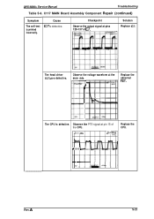
C117 MAIN Board Assembly Component Repair (continued) Symptom The self-test is defective. Cause IC7 is printed incorrectly. Observe the voltage waveform at pins 129-137 of the CPU. LIVH j2QV AT. Checkpoint Observe the output signal at the drain side. BVI Uv Replace the abnormal FET. The CPU is defective. F\ + ++++ 5V 1 Rev. Solution Replace IC7. The head driver FETs are defective. Observe the PTS signal at pin 15 of IC7. A S-23 DFX-5000+ Service Manual Troubleshooting Table 5-6. l,92ms SAVE Replace the CPU.
C117 MAIN Board Assembly Component Repair (continued) Symptom The self-test is defective. Cause IC7 is printed incorrectly. Observe the voltage waveform at pins 129-137 of the CPU. LIVH j2QV AT. Checkpoint Observe the output signal at the drain side. BVI Uv Replace the abnormal FET. The CPU is defective. F\ + ++++ 5V 1 Rev. Solution Replace IC7. The head driver FETs are defective. Observe the PTS signal at pin 15 of IC7. A S-23 DFX-5000+ Service Manual Troubleshooting Table 5-6. l,92ms SAVE Replace the CPU.

Service Manual
Page 162
...pinion gear and paper feed reduction gear. Remove any foreign substances. DFX-5000+ Service Manual Troubleshooting Table 5-7. The Pfinthead is defective. Print density differs..., replace main board at the right and left sides of a dot wire is worn. Replace the PF motor, and if drivers are..., ribbon feed transmission gear, or ribbon feed gear). Check whether a dot wire is worn. Visually check the paper path. Cause The printhead is... smoothly when rotated manually. A S-25 Printing is performed, but the printer does not feed paper or does not feed it feeds the ribbon normally...
...pinion gear and paper feed reduction gear. Remove any foreign substances. DFX-5000+ Service Manual Troubleshooting Table 5-7. The Pfinthead is defective. Print density differs..., replace main board at the right and left sides of a dot wire is worn. Replace the PF motor, and if drivers are..., ribbon feed transmission gear, or ribbon feed gear). Check whether a dot wire is worn. Visually check the paper path. Cause The printhead is... smoothly when rotated manually. A S-25 Printing is performed, but the printer does not feed paper or does not feed it feeds the ribbon normally...

Service Manual
Page 164
... crumpled at the front or rear tractor assembly. Visually check the tractor select gear holder. Rev. The tractor select sensor is not working. Printer Mechanism Repair (continued) Symptom Printing occurs outside the paper width. Checkpoint Solution Check the PWsensor. Check the coil resistance of the tractor select sensor. The... plunger is incorrect. The paper bail assembly does not work. Replace the plunger. Join the tip of the tractor wire spring is defective. DFX-5000+ Service Manual Troubleshooting Table 5-7. Replace the tractor select sensor.
... crumpled at the front or rear tractor assembly. Visually check the tractor select gear holder. Rev. The tractor select sensor is not working. Printer Mechanism Repair (continued) Symptom Printing occurs outside the paper width. Checkpoint Solution Check the PWsensor. Check the coil resistance of the tractor select sensor. The... plunger is incorrect. The paper bail assembly does not work. Replace the plunger. Join the tip of the tractor wire spring is defective. DFX-5000+ Service Manual Troubleshooting Table 5-7. Replace the tractor select sensor.


