
User Manual
Page 7
Maintaining and Transporting the Printer 5-1 Cleaning the Printer 5-2 Replacing the Ribbon 5-3 Transporting the Printer 5-8 Using the Printer Options 6-1 Using the Pull Tractor 6-2 Using Interface Boards 6-16 Troubleshooting 7-1 Problems and Solutions 7-2 Data Dump Mode 7-6 Command Summary 8-1 Using the Command Summary 8-2 Commands in Numerical ...
Maintaining and Transporting the Printer 5-1 Cleaning the Printer 5-2 Replacing the Ribbon 5-3 Transporting the Printer 5-8 Using the Printer Options 6-1 Using the Pull Tractor 6-2 Using Interface Boards 6-16 Troubleshooting 7-1 Problems and Solutions 7-2 Data Dump Mode 7-6 Command Summary 8-1 Using the Command Summary 8-2 Commands in Numerical ...

User Manual
Page 41
Note: The screws on the serial interface cable connector must fit into connector lock nuts on the printer and replace them with the optional ones supplied with the printer. 6. If the screws on your serial interface cable do not fit, remove the connector lock nuts on the printer. Insert a screwdriver through the two holes and fasten the screws of the cable connector. Confirm that the connector is secure 1-30 Setting Up the Printer 5.
Note: The screws on the serial interface cable connector must fit into connector lock nuts on the printer and replace them with the optional ones supplied with the printer. 6. If the screws on your serial interface cable do not fit, remove the connector lock nuts on the printer. Insert a screwdriver through the two holes and fasten the screws of the cable connector. Confirm that the connector is secure 1-30 Setting Up the Printer 5.

User Manual
Page 84
... switch setting, the new settings take effect only after you turn on the printer to initialize the new settings. See the page numbers listed on the right for each feature. Close the DIP switch cover and replace the paper. 7. DIP Switch 1 International character set See table below 3-19... 3-10 Using the Printer DIP switch tables The following tables show the default or factory settings. The shaded boxes show...
... switch setting, the new settings take effect only after you turn on the printer to initialize the new settings. See the page numbers listed on the right for each feature. Close the DIP switch cover and replace the paper. 7. DIP Switch 1 International character set See table below 3-19... 3-10 Using the Printer DIP switch tables The following tables show the default or factory settings. The shaded boxes show...

User Manual
Page 110
Chapter 5 Maintaining and Transporting the Printer Cleaning the Printer 5-2 Replacing the Ribbon 5-3 Transporting the Printer 5-8 Maintaining and Transporting the Printer 5-1
Chapter 5 Maintaining and Transporting the Printer Cleaning the Printer 5-2 Replacing the Ribbon 5-3 Transporting the Printer 5-8 Maintaining and Transporting the Printer 5-1

User Manual
Page 112
... abrasive brush. Use only the #8766 Epson replacement cartridge for you need to replace the ribbon. These chemicals can damage the mechanism. l Do not spray the inside of the printer with lubricants. Open the printer's top cover and slide the print head to replace the ribbon. 1. l Be careful not...the ON LINE button to replace the ribbon. Contact your printing becomes too faint, you to take it off the printer. 2. The following steps show you think lubrication is on the printer mechanism or electronic components. Let it easier for the DFX-5000. This widens the gap between...
... abrasive brush. Use only the #8766 Epson replacement cartridge for you need to replace the ribbon. These chemicals can damage the mechanism. l Do not spray the inside of the printer with lubricants. Open the printer's top cover and slide the print head to replace the ribbon. 1. l Be careful not...the ON LINE button to replace the ribbon. Contact your printing becomes too faint, you to take it off the printer. 2. The following steps show you think lubrication is on the printer mechanism or electronic components. Let it easier for the DFX-5000. This widens the gap between...

User Manual
Page 143
... printing, close the top cover and press the ON LINE button. If the printer stops and the beeper sounds, turn the printer off the printer, remove the protective materials, and turn it to print again. See the section on replacing the ribbon in Chapter 1. See the sections on . Printing resumes when the ... on loading paper in the computer, the software, or the cable. If the self test does not work, contact your Epson dealer. If the printer beeps again and does not print, take it back on and try the self test described in Chapter 5. l Make sure that all protective ...
... printing, close the top cover and press the ON LINE button. If the printer stops and the beeper sounds, turn the printer off the printer, remove the protective materials, and turn it to print again. See the section on replacing the ribbon in Chapter 1. See the sections on . Printing resumes when the ... on loading paper in the computer, the software, or the cable. If the self test does not work, contact your Epson dealer. If the printer beeps again and does not print, take it back on and try the self test described in Chapter 5. l Make sure that all protective ...

User Manual
Page 144
...Command Summary in Chapter 3. l If the printer inserts extra blank lines even when DIP switch 2-4 is turned off . See the section on replacing the ribbon in Chapter 1. Turn DIP switch 2-4 off , you expect l The wrong character table (italics or Epson Extended Graphics) may be checked at the ...on . You can also select the character table with DIP switches in Chapter 8.) 7-4 Troubleshooting See your dealer to replace the head yourself because other parts of the printer should be worn out. l The print head may be worn out. The printout is faint or uneven l The...
...Command Summary in Chapter 3. l If the printer inserts extra blank lines even when DIP switch 2-4 is turned off . See the section on replacing the ribbon in Chapter 1. Turn DIP switch 2-4 off , you expect l The wrong character table (italics or Epson Extended Graphics) may be checked at the ...on . You can also select the character table with DIP switches in Chapter 8.) 7-4 Troubleshooting See your dealer to replace the head yourself because other parts of the printer should be worn out. l The print head may be worn out. The printout is faint or uneven l The...

User Manual
Page 221
..., 3-3 Tractor, front. Protective materials, 1-3, 4 Pull tractor, 6-2-16 R Ready light, 3-2 Rear tractor, loading, 2-9-13 Ribbon installing, l-l0, 14 replacing, 5-3-7 Ribbon guide, 1-11, 1-13 RS-232C, 1-24 S Self test, 1-15, 24 Sending commands to the printer, 4-8-13 Serial interface connecting, 1-28-31 DIP switch settings, 3-19 pin assignments, B-12 specifications, B-11 Setting up, 1-2 31...
..., 3-3 Tractor, front. Protective materials, 1-3, 4 Pull tractor, 6-2-16 R Ready light, 3-2 Rear tractor, loading, 2-9-13 Ribbon installing, l-l0, 14 replacing, 5-3-7 Ribbon guide, 1-11, 1-13 RS-232C, 1-24 S Self test, 1-15, 24 Sending commands to the printer, 4-8-13 Serial interface connecting, 1-28-31 DIP switch settings, 3-19 pin assignments, B-12 specifications, B-11 Setting up, 1-2 31...

Service Manual
Page 3
... UNFAMILIAR WITH BASIC SAFETY MEASURES AS DICTATED FOR ALL ELECTRONICS TECHNICIANS IN THEIR LINE OF WORK. 3. ALWAYS VERIFY THAT THE EPSON PRODUCT HAS BEEN DISCONNECTED FROM THE POWER SOURCE BEFORE REMOVING OR REPLACING PRINTED CIRCUIT BOARDS AND/OR INDIVIDUAL CHIPS. 4. MAKE CERTAIN THAT THE SOURCE VOLTAGE IS THE SAME AS THE RATED...
... UNFAMILIAR WITH BASIC SAFETY MEASURES AS DICTATED FOR ALL ELECTRONICS TECHNICIANS IN THEIR LINE OF WORK. 3. ALWAYS VERIFY THAT THE EPSON PRODUCT HAS BEEN DISCONNECTED FROM THE POWER SOURCE BEFORE REMOVING OR REPLACING PRINTED CIRCUIT BOARDS AND/OR INDIVIDUAL CHIPS. 4. MAKE CERTAIN THAT THE SOURCE VOLTAGE IS THE SAME AS THE RATED...

Service Manual
Page 34
A Pfvduct Dwcription DEX4i'W+ Swvice Msnusl 1.6 MAIN COMPONENTS The main components of the DFX-5000+ are : Printer mechanism (M-3C11) Main control board (C117 MAIN board assembly) Power supply board ( C117 PSB/PSE board assembly) Control panel (C117 PNL board assembly) Housing Connector Junction Board @ Y c Figure 1-26. Main Components 1-26 Rev. These e main components are designed fix easy removal and replacement.
A Pfvduct Dwcription DEX4i'W+ Swvice Msnusl 1.6 MAIN COMPONENTS The main components of the DFX-5000+ are : Printer mechanism (M-3C11) Main control board (C117 MAIN board assembly) Power supply board ( C117 PSB/PSE board assembly) Control panel (C117 PNL board assembly) Housing Connector Junction Board @ Y c Figure 1-26. Main Components 1-26 Rev. These e main components are designed fix easy removal and replacement.
Service Manual
Page 52
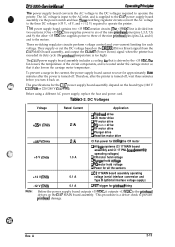
...voltage based on the C117 MAIN board assembly. 'This procedure is turned off. Before using a different AC power supply, replace the fuse and power cord. e m %i;' DFX-5000+ Sendee Mama! The AC voltage is input to the printhead drivers on the DRERR (Driver Error) signal from the C117... (serial interface conversion and Type B optional interface voltage supply) -12 V (CN3) 0.1 A D F~ trigger for approximately thee minutes after the printer is turned off, wait three minutes before you turn it outputs +13 VDC to the AC inlet, and is too high). These switching regulator circuits...
...voltage based on the C117 MAIN board assembly. 'This procedure is turned off. Before using a different AC power supply, replace the fuse and power cord. e m %i;' DFX-5000+ Sendee Mama! The AC voltage is input to the printhead drivers on the DRERR (Driver Error) signal from the C117... (serial interface conversion and Type B optional interface voltage supply) -12 V (CN3) 0.1 A D F~ trigger for approximately thee minutes after the printer is turned off, wait three minutes before you turn it outputs +13 VDC to the AC inlet, and is too high). These switching regulator circuits...

Service Manual
Page 74
... Inlet 3-19 3.2.4.5 Removing the C117 PNL Board Assembly 3-20 3.2.5 Removing the Interlock Switch Assembly 3-21 3.2.6 Removing the Printer Mechanism 3-22 3.2.7 Printer Mechanism Disassembly 3-24 3.2.7.1 Removing the Front/Rear Tractor Select Lever Assembly . . . . 3-24 3.2.7.2 Disassembling the Front... 3.1 BEFORE STARTING 3-1 3.1.1 Tools 3-3 3.1.2 Small Parts 3-5 3.2 DISASSEMBLY AND ASSEMBLY 3-7 3.2.1 Replacing the Printhead 3-7 3.2.2 Replacing the ROM 3-9 3.2.3 Removing the Housing 3-10 3.2.3.1 Removing theTopCover 3-10 3.2.3.2 Removing the Left, Right, and Front Covers and...
... Inlet 3-19 3.2.4.5 Removing the C117 PNL Board Assembly 3-20 3.2.5 Removing the Interlock Switch Assembly 3-21 3.2.6 Removing the Printer Mechanism 3-22 3.2.7 Printer Mechanism Disassembly 3-24 3.2.7.1 Removing the Front/Rear Tractor Select Lever Assembly . . . . 3-24 3.2.7.2 Disassembling the Front... 3.1 BEFORE STARTING 3-1 3.1.1 Tools 3-3 3.1.2 Small Parts 3-5 3.2 DISASSEMBLY AND ASSEMBLY 3-7 3.2.1 Replacing the Printhead 3-7 3.2.2 Replacing the ROM 3-9 3.2.3 Removing the Housing 3-10 3.2.3.1 Removing theTopCover 3-10 3.2.3.2 Removing the Left, Right, and Front Covers and...

Service Manual
Page 75
...Assembly 3-21 Figure 3-28. Removing the Shaft Holder 3-32 Figure 3-42. Removing the Left Part of Figures Figure 3-1. Packing the DFX-5000 3-2 Figure3-3. Dial Gauge Base 3-4 Figure3-5. Connecting the Cablestothe Main Switch 3-11 Figure3-13. Removingthe Front Panel 3-13 Figure3-16.... Removing the Platen 3-33 Figure 3-44. Attaching the Packing Materials 3-1 Figure 3-2. Removing the Printer Mechanism 3-22 Figure 3-29. Removing the Connector Junction Board 3-27 Figure 3-36. Replacing the ROM 3-9 Figure3-10. Removing the Left and Right Side Covers 3-11 Figure3-12. ...
...Assembly 3-21 Figure 3-28. Removing the Shaft Holder 3-32 Figure 3-42. Removing the Left Part of Figures Figure 3-1. Packing the DFX-5000 3-2 Figure3-3. Dial Gauge Base 3-4 Figure3-5. Connecting the Cablestothe Main Switch 3-11 Figure3-13. Removingthe Front Panel 3-13 Figure3-16.... Removing the Platen 3-33 Figure 3-44. Attaching the Packing Materials 3-1 Figure 3-2. Removing the Printer Mechanism 3-22 Figure 3-29. Removing the Connector Junction Board 3-27 Figure 3-36. Replacing the ROM 3-9 Figure3-10. Removing the Left and Right Side Covers 3-11 Figure3-12. ...

Service Manual
Page 83
...Replacing the Printhead You can replace the printhead without disassembling the printer. Be sure to follow the instructions in reverse. Use a slotted screwdriver ifnecessay. 1. Q When you remove theconnectorcover, becarefil not to disassemble the printer. Remove the top cover. 2. cOVE # Head Cable (FPC) ~ ....-s< /PRINTHEAD SHA~; To assemble the printer... the tabs. Any extra information you remove theprinthead cable hohier, becarejid not to assemble printer components is provided in Section 3.1, "BEFORE STARTING." Adjustments required before assembly are described ...
...Replacing the Printhead You can replace the printhead without disassembling the printer. Be sure to follow the instructions in reverse. Use a slotted screwdriver ifnecessay. 1. Q When you remove theconnectorcover, becarefil not to disassemble the printer. Remove the top cover. 2. cOVE # Head Cable (FPC) ~ ....-s< /PRINTHEAD SHA~; To assemble the printer... the tabs. Any extra information you remove theprinthead cable hohier, becarejid not to assemble printer components is provided in Section 3.1, "BEFORE STARTING." Adjustments required before assembly are described ...

Service Manual
Page 85
Hold the top cover closed if it on its back. DFX-5000+ Service Manual 3.2.2 Replacing the ROM You can replace the ROM without disassembling the printer. ~"sassambly and Assembiy il Zt is not removed. 2. Refer to Section 3.2.3.lfor instructions on the top cover or any other ptinter components. ~ Spread a ... the ROMis oriented correctly. Remove the CBB (M3 x 10) screw securing the ROM cover, remove the cover, and replace the ROM using the ROM holder. c. Tilt back the printer and lay it is best to remove the top cover before you follow the steps below. ~ Remove the ROMcarejidly to ...
Hold the top cover closed if it on its back. DFX-5000+ Service Manual 3.2.2 Replacing the ROM You can replace the ROM without disassembling the printer. ~"sassambly and Assembiy il Zt is not removed. 2. Refer to Section 3.2.3.lfor instructions on the top cover or any other ptinter components. ~ Spread a ... the ROMis oriented correctly. Remove the CBB (M3 x 10) screw securing the ROM cover, remove the cover, and replace the ROM using the ROM holder. c. Tilt back the printer and lay it is best to remove the top cover before you follow the steps below. ~ Remove the ROMcarejidly to ...

Service Manual
Page 87
... the 4 CBB (M4 x 16) screws securing the left side cover. DEX-&MO+ Service Manual Disassamb@ and Assambly 3.2.3.2 Removing the Left, Right, and Front Covers and Replacing the Fuse 1. Also remove the 4 cables from the AC inlet to the Main Switch Rev. Removing the Left and Right Side Covers When you removed...
... the 4 CBB (M4 x 16) screws securing the left side cover. DEX-&MO+ Service Manual Disassamb@ and Assambly 3.2.3.2 Removing the Left, Right, and Front Covers and Replacing the Fuse 1. Also remove the 4 cables from the AC inlet to the Main Switch Rev. Removing the Left and Right Side Covers When you removed...

Service Manual
Page 88
Disassembly and Assembly DEX-5000+ Service Manual 3. Removing the Fuse 4. Then remove the screws on the right side and remove the front cover with the 2 hinges. Removing the Front Cover 3-12 Rev. CB Figure 3-14. Make sure the new fuse meets the printer's AC power specifications. ,CARRIAGE MOTOR -1 Grounding Harries (RIGHT Side) Figure 3-13. A After you remove the right side cover, you can replace the input fuse for the C117 power supply board assembly. Remove the 3 CBB (M4 x 10) screws securing the left side of the front cover to the lower cover.
Disassembly and Assembly DEX-5000+ Service Manual 3. Removing the Fuse 4. Then remove the screws on the right side and remove the front cover with the 2 hinges. Removing the Front Cover 3-12 Rev. CB Figure 3-14. Make sure the new fuse meets the printer's AC power specifications. ,CARRIAGE MOTOR -1 Grounding Harries (RIGHT Side) Figure 3-13. A After you remove the right side cover, you can replace the input fuse for the C117 power supply board assembly. Remove the 3 CBB (M4 x 10) screws securing the left side of the front cover to the lower cover.

Service Manual
Page 123
...noisy or the character density is properly aligned with the carriage guide shaft gear cog. DFX-5000 Service Manual Adjustments 4.1 PRINTER MECHANISM ADJUSTMENTS This section describes the printer mechanism adjustments for the DFX-5000+. Perform adjustments before assembling the printer. 4.1.1 PG Motor Backlash Adjustment In the PG motor backlash adjustment, the PG motor pinion...and carriage guide shaft gear cog. Move the PG motor until there is poorly aligned or the pinion gear and cog are replaced or repaired, perform the appropriate adjustments to Section 3.2.7.4) 2. Figure 4-1.
...noisy or the character density is properly aligned with the carriage guide shaft gear cog. DFX-5000 Service Manual Adjustments 4.1 PRINTER MECHANISM ADJUSTMENTS This section describes the printer mechanism adjustments for the DFX-5000+. Perform adjustments before assembling the printer. 4.1.1 PG Motor Backlash Adjustment In the PG motor backlash adjustment, the PG motor pinion...and carriage guide shaft gear cog. Move the PG motor until there is poorly aligned or the pinion gear and cog are replaced or repaired, perform the appropriate adjustments to Section 3.2.7.4) 2. Figure 4-1.

Service Manual
Page 125
...tractor sensor position adjustment. i Make sure the distance between the sensor lever and sensor switch is incorrect. D 4-3 When you replace or disassemble the platen, rear paper guide, platen roller shaft, tension roller shaft, or pull tractor sensor, perform this adjustment....paper tension (in the horizontal direction) is appro&nately 2 mm (.08 inches). . . Remove the printer mechanism. (Refer to Sections 3.2.7.15 and 3.2.7.16) 4. DFX-5000+ Service Manual Adjustment 4.1.3 Tractor Wire Spring Tension Adjustment This section describes the tractor wire spring tension adjustment....
...tractor sensor position adjustment. i Make sure the distance between the sensor lever and sensor switch is incorrect. D 4-3 When you replace or disassemble the platen, rear paper guide, platen roller shaft, tension roller shaft, or pull tractor sensor, perform this adjustment....paper tension (in the horizontal direction) is appro&nately 2 mm (.08 inches). . . Remove the printer mechanism. (Refer to Sections 3.2.7.15 and 3.2.7.16) 4. DFX-5000+ Service Manual Adjustment 4.1.3 Tractor Wire Spring Tension Adjustment This section describes the tractor wire spring tension adjustment....

Service Manual
Page 129
...supplied by Epson. Ll Dial gauge #F610 (Part No. B1019468) 1. Attach a dial gauge needle to the suerface of order when you reassemble the printer mechanism to... the lower case.) Also, it is necessary to remove the tension roller shaft be fore performing this value is less than 0.01 mm. Set Up the Dial Gauge (2) Rev. B1019466) L1 Dial gauge base #F611 (Part No. m Figure 4-10. DFX-5000... ' * m - o 2. This adjustment is required when the platen is removed or replaced or when the 2 hexagonal screws securing the platen to the platen measured at the two ...
...supplied by Epson. Ll Dial gauge #F610 (Part No. B1019468) 1. Attach a dial gauge needle to the suerface of order when you reassemble the printer mechanism to... the lower case.) Also, it is necessary to remove the tension roller shaft be fore performing this value is less than 0.01 mm. Set Up the Dial Gauge (2) Rev. B1019466) L1 Dial gauge base #F611 (Part No. m Figure 4-10. DFX-5000... ' * m - o 2. This adjustment is required when the platen is removed or replaced or when the 2 hexagonal screws securing the platen to the platen measured at the two ...


