

FE 123 & 124 Users Manual
Page 1
® Fluke 123/124 Industrial ScopeMeter GB Sep 2002 © 2002 Fluke Corporation. Users Manual All product names are trademarks of their respective companies. All rights reserved.
® Fluke 123/124 Industrial ScopeMeter GB Sep 2002 © 2002 Fluke Corporation. Users Manual All product names are trademarks of their respective companies. All rights reserved.

FE 123 & 124 Users Manual
Page 6
Fluke 123/124 Users Manual Freezing the Screen...16 Holding a Stable Reading 16 Making Relative Measurements 17 Selecting Auto/Manual Ranges 18 Changing the Graphic Representation on the Screen 18 TrendPlotting a Waveform 22 Acquiring the Waveform 23 Triggering on a Waveform 27 Saving and Recalling a Setup ...
Fluke 123/124 Users Manual Freezing the Screen...16 Holding a Stable Reading 16 Making Relative Measurements 17 Selecting Auto/Manual Ranges 18 Changing the Graphic Representation on the Screen 18 TrendPlotting a Waveform 22 Acquiring the Waveform 23 Triggering on a Waveform 27 Saving and Recalling a Setup ...

FE 123 & 124 Users Manual
Page 8
Fluke 123/124 Users Manual iv
Fluke 123/124 Users Manual iv

FE 123 & 124 Users Manual
Page 10
Fluke 123/124 Users Manual Unpacking the Test Tool Kit The following items are included in your test tool kit. (see Figure 1.): # Description 1 Fluke Test Tool 2 Rechargeable Battery Pack 3 Power Adapter/Battery Charger 4 Shielded Test Leads with Black...Users Manuals 11 Shipment Box 12 Optically Isolated RS-232 Adapter/Cable 13 FlukeView ScopeMeter Software for Windows 14 Hard Carrying Case 15 10:1 Voltage Probe Note When new, the rechargeable battery pack is not fully charged. Fluke 123 Model 123 NiCd 1x Fluke 123/S Model 123 NiCd 2x) • • • • • Fluke 124...
Fluke 123/124 Users Manual Unpacking the Test Tool Kit The following items are included in your test tool kit. (see Figure 1.): # Description 1 Fluke Test Tool 2 Rechargeable Battery Pack 3 Power Adapter/Battery Charger 4 Shielded Test Leads with Black...Users Manuals 11 Shipment Box 12 Optically Isolated RS-232 Adapter/Cable 13 FlukeView ScopeMeter Software for Windows 14 Hard Carrying Case 15 10:1 Voltage Probe Note When new, the rechargeable battery pack is not fully charged. Fluke 123 Model 123 NiCd 1x Fluke 123/S Model 123 NiCd 2x) • • • • • Fluke 124...

FE 123 & 124 Users Manual
Page 12
... Warning Should this test tool be found throughout the manual. A Caution identifies conditions and actions that pose hazard(s) to the user. Warning To avoid electrical shock, use only Fluke power supply, Model PM8907 (Power Adapter/Battery Charger). 4 See explanation in the next table. Fluke 123/124 Users Manual Safely Using the Test Tool Attention Carefully read the...
... Warning Should this test tool be found throughout the manual. A Caution identifies conditions and actions that pose hazard(s) to the user. Warning To avoid electrical shock, use only Fluke power supply, Model PM8907 (Power Adapter/Battery Charger). 4 See explanation in the next table. Fluke 123/124 Users Manual Safely Using the Test Tool Attention Carefully read the...

FE 123 & 124 Users Manual
Page 14
...300 V CAT III Input A and B via STL120 600 V CAT III Max. The terms 'Isolated' or 'Electrically floating' are used in this manual to indicate a measurement in which the Test Tool's Shielded Banana inputs or banana jack is likely that safety has been impaired, the Test Tool must...disconnected from earth ground. The isolated input connectors have no exposed metal and are fully insulated to a voltage different from the line power. Fluke 123/124 Users Manual • Do not insert metal objects into connectors. • Always use , inspect the test leads for mechanical damage and replace damaged...
...300 V CAT III Input A and B via STL120 600 V CAT III Max. The terms 'Isolated' or 'Electrically floating' are used in this manual to indicate a measurement in which the Test Tool's Shielded Banana inputs or banana jack is likely that safety has been impaired, the Test Tool must...disconnected from earth ground. The isolated input connectors have no exposed metal and are fully insulated to a voltage different from the line power. Fluke 123/124 Users Manual • Do not insert metal objects into connectors. • Always use , inspect the test leads for mechanical damage and replace damaged...

FE 123 & 124 Users Manual
Page 16
Release. The F4 key of Fluke 123 is used to switch the cursors on , and you should hear a double beep, indicating the Reset was successful. Fluke 123 Fluke 124 Figure 1-2. The Screen After Reset 8 The test tool turns on . you want to restore the test tool settings as delivered from the factory, do the following: Turn the test tool off. in Fluke 124 this key is used to control the contrast; Press and hold. Now look at the display; Fluke 123/124 Users Manual Resetting the Test Tool If you will see a screen that looks like Figure 1-2. Press and release.
Release. The F4 key of Fluke 123 is used to switch the cursors on , and you should hear a double beep, indicating the Reset was successful. Fluke 123 Fluke 124 Figure 1-2. The Screen After Reset 8 The test tool turns on . you want to restore the test tool settings as delivered from the factory, do the following: Turn the test tool off. in Fluke 124 this key is used to control the contrast; Press and hold. Now look at the display; Fluke 123/124 Users Manual Resetting the Test Tool If you will see a screen that looks like Figure 1-2. Press and release.

FE 123 & 124 Users Manual
Page 18
... that provides choices available through the blue function keys. The area displays one or more menus with choices accessed with the arrow keys: . 10 Fluke 123 Fluke 124 Figure 1-3. Fluke 123/124 Users Manual Reading the Screen The screen is on , you change a setup, a part of the battery from full to empty: . The Screen Area's Waveform area...
... that provides choices available through the blue function keys. The area displays one or more menus with choices accessed with the arrow keys: . 10 Fluke 123 Fluke 124 Figure 1-3. Fluke 123/124 Users Manual Reading the Screen The screen is on , you change a setup, a part of the battery from full to empty: . The Screen Area's Waveform area...

FE 123 & 124 Users Manual
Page 20
... use the black COMmon as single ground for low frequency measurements, and for all connections to COM are at the top of the test tool. Fluke 123/124 Users Manual Looking at the Measurement Connections Look at the same potential. 12 Figure 1-5.
... use the black COMmon as single ground for low frequency measurements, and for all connections to COM are at the top of the test tool. Fluke 123/124 Users Manual Looking at the Measurement Connections Look at the same potential. 12 Figure 1-5.

FE 123 & 124 Users Manual
Page 22
... measured. Observe that is now the main reading. The former main reading has now moved to the smaller secondary reading position. (See Figure 1-8.) 14 Fluke 123/124 Users Manual Making Measurements The reading area displays the numeric readings of the chosen measurements on the waveform that Hz is applied to the input jack. •...
... measured. Observe that is now the main reading. The former main reading has now moved to the smaller secondary reading position. (See Figure 1-8.) 14 Fluke 123/124 Users Manual Making Measurements The reading area displays the numeric readings of the chosen measurements on the waveform that Hz is applied to the input jack. •...

FE 123 & 124 Users Manual
Page 24
... at any time. TOUCH HOLD OFF appears on bottom of the reading area. BEEP))) Wait until an audible beep: now you maintain the measurement connections. Fluke 123/124 Users Manual Freezing the Screen You can use this function for the Touch Hold function: Open the INPUT A menu. Freeze the screen.
... at any time. TOUCH HOLD OFF appears on bottom of the reading area. BEEP))) Wait until an audible beep: now you maintain the measurement connections. Fluke 123/124 Users Manual Freezing the Screen You can use this function for the Touch Hold function: Open the INPUT A menu. Freeze the screen.

FE 123 & 124 Users Manual
Page 26
...base, and triggering. MANUAL appears at the bottom of the reading area disappears to 5 s/div in normal mode. Changing the Amplitude Enlarge the waveform. Reduce the waveform. Available settings are from 20 ns/div (Fluke 123) or 10 ns/div (Fluke 124) to indicate that ...of periods. Decrease the number of the reading area. This assures a stable display on the screen manually. Fluke 123/124 Users Manual Selecting Auto/Manual Ranges Press to select the manual range. Changing the Graphic Representation on the Screen From Auto range, you can use the light-gray...
...base, and triggering. MANUAL appears at the bottom of the reading area disappears to 5 s/div in normal mode. Changing the Amplitude Enlarge the waveform. Reduce the waveform. Available settings are from 20 ns/div (Fluke 123) or 10 ns/div (Fluke 124) to indicate that ...of periods. Decrease the number of the reading area. This assures a stable display on the screen manually. Fluke 123/124 Users Manual Selecting Auto/Manual Ranges Press to select the manual range. Changing the Graphic Representation on the Screen From Auto range, you can use the light-gray...

FE 123 & 124 Users Manual
Page 28
You can use waveform smooth to WAVEFORM MODE. Jump to suppress noise without smoothing are shown in Figure 1-11. 20 Figure 1-11. Fluke 123/124 Users Manual Smoothing the Waveform To smooth the waveform, do the following: Open the SCOPE INPUTS menu. Waveform samples with and without loss of bandwidth. Accept waveform smooth. Smoothing the Waveform Highlight SMOOTH. Open the SCOPE OPTIONS submenu.
You can use waveform smooth to WAVEFORM MODE. Jump to suppress noise without smoothing are shown in Figure 1-11. 20 Figure 1-11. Fluke 123/124 Users Manual Smoothing the Waveform To smooth the waveform, do the following: Open the SCOPE INPUTS menu. Waveform samples with and without loss of bandwidth. Accept waveform smooth. Smoothing the Waveform Highlight SMOOTH. Open the SCOPE OPTIONS submenu.

FE 123 & 124 Users Manual
Page 30
... about half the screen. Figure 1-13. The test tool records the minimum (MIN) reading as the main (upper displayed) measurement of time. Start TRENDPLOT. Fluke 123/124 Users Manual TrendPlotting a Waveform The TrendPlot™ function plots the digital readings as a function of input A. The automatic time scaling then compresses this information to right until...
... about half the screen. Figure 1-13. The test tool records the minimum (MIN) reading as the main (upper displayed) measurement of time. Start TRENDPLOT. Fluke 123/124 Users Manual TrendPlotting a Waveform The TrendPlot™ function plots the digital readings as a function of input A. The automatic time scaling then compresses this information to right until...

FE 123 & 124 Users Manual
Page 32
The test tool will now have a screen like Figure 1-14. Hold appears on bottom of the screen when the single acquisition is waiting for another single acquisition trigger. To perform a next single acquisition, do the following: Wait for a trigger. Making a Single Acquisition 24 Run appears on bottom of the screen when the single acquisition has been completed. Figure 1-14. Fluke 123/124 Users Manual Wait appears on bottom of the screen to indicate that the test tool is triggered.
The test tool will now have a screen like Figure 1-14. Hold appears on bottom of the screen when the single acquisition is waiting for another single acquisition trigger. To perform a next single acquisition, do the following: Wait for a trigger. Making a Single Acquisition 24 Run appears on bottom of the screen when the single acquisition has been completed. Figure 1-14. Fluke 123/124 Users Manual Wait appears on bottom of the screen to indicate that the test tool is triggered.

FE 123 & 124 Users Manual
Page 34
.... An inverted display is displayed as positive-going, providing a more meaningful viewing perspective in some cases. Highlight AC. (4x) Accept AC-coupling for INPUT A. Fluke 123/124 Users Manual Selecting AC-Coupling Use AC-coupling when you wish to observe a small AC signal that rides on left of the waveform area. 26 For example...
.... An inverted display is displayed as positive-going, providing a more meaningful viewing perspective in some cases. Highlight AC. (4x) Accept AC-coupling for INPUT A. Fluke 123/124 Users Manual Selecting AC-Coupling Use AC-coupling when you wish to observe a small AC signal that rides on left of the waveform area. 26 For example...

FE 123 & 124 Users Manual
Page 36
... INPUTS menu. Accept all trigger selections and return to >1Hz will slow down the auto range. Select FREE RUN. Highlight FREE RUN. Highlight Input 'A'. Fluke 123/124 Users Manual Selecting the Trigger Parameters To trigger on bottom of the screen when no trigger is not valid. Select Input 'A'. Open the TRIGGER submenu. Note Setting...
... INPUTS menu. Accept all trigger selections and return to >1Hz will slow down the auto range. Select FREE RUN. Highlight FREE RUN. Highlight Input 'A'. Fluke 123/124 Users Manual Selecting the Trigger Parameters To trigger on bottom of the screen when no trigger is not valid. Select Input 'A'. Open the TRIGGER submenu. Note Setting...

FE 123 & 124 Users Manual
Page 38
Accept the video trigger selections . Figure 1-18. Measuring Video Signals 30 Fluke 123/124 Users Manual Highlight POSITIVE. Trigger level and slope are now fixed. (See Figure 1-18.) Positive video is indicated as a "+" icon on bottom of the screen.
Accept the video trigger selections . Figure 1-18. Measuring Video Signals 30 Fluke 123/124 Users Manual Highlight POSITIVE. Trigger level and slope are now fixed. (See Figure 1-18.) Positive video is indicated as a "+" icon on bottom of the screen.
FE 123 & 124 Users Manual
Page 40
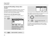
... SAVE/PRINT menu. is already highlighted and that SAVE ... Save the actual screen and settings. In each memory you leave the SAVE/PRINT menu again. Fluke 123/124 Users Manual Saving and Recalling a Setup and a Screen You can save Screens and Setups to normal signal acquisition again. The actual screen and settings are indicated...
... SAVE/PRINT menu. is already highlighted and that SAVE ... Save the actual screen and settings. In each memory you leave the SAVE/PRINT menu again. Fluke 123/124 Users Manual Saving and Recalling a Setup and a Screen You can save Screens and Setups to normal signal acquisition again. The actual screen and settings are indicated...

FE 123 & 124 Users Manual
Page 42
... the instrument returns to clear all or just 1 screen + setups, do the following : Open the SAVE/PRINT menu. memory 7), do the following : Highlight DELETE ... submenu. Fluke 123/124 Users Manual Deleting Screens and Associated Setups To delete all memory locations, press F3 DELETE ALL.
... the instrument returns to clear all or just 1 screen + setups, do the following : Open the SAVE/PRINT menu. memory 7), do the following : Highlight DELETE ... submenu. Fluke 123/124 Users Manual Deleting Screens and Associated Setups To delete all memory locations, press F3 DELETE ALL.


