Fluke 1750 Three Phase Power Recorder Datasheet
Page 5
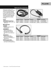
... cm (24 in) 60 cm (24 in) 60 cm (24 in) 120 cm (48 in ) dia. Additional SEAT LICENSE • One additional license for Fluke 1750 1750/SEAT-L • Fluke Power Analyze - All clamp-on unlimited PCs 4006 Security Cable • 1.8 m (6 ft) looped lockable steel cable for securing monitor Model No. 3005-PR 3014-PR... 3210-PR 3310-PR 3312-PR CT Type Flexi-CT Flexi-CT Flexi-CT Flexi-CT Current Range 0.01 A to 5 A 0.1 A to 40 A 2 A to set scale factors for accurate readings.
... cm (24 in) 60 cm (24 in) 60 cm (24 in) 120 cm (48 in ) dia. Additional SEAT LICENSE • One additional license for Fluke 1750 1750/SEAT-L • Fluke Power Analyze - All clamp-on unlimited PCs 4006 Security Cable • 1.8 m (6 ft) looped lockable steel cable for securing monitor Model No. 3005-PR 3014-PR... 3210-PR 3310-PR 3312-PR CT Type Flexi-CT Flexi-CT Flexi-CT Flexi-CT Current Range 0.01 A to 5 A 0.1 A to 40 A 2 A to set scale factors for accurate readings.
Fluke 1750 Three Phase Power Recorder Datasheet
Page 6
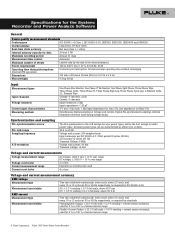
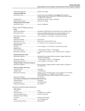
...current sensor accuracy), valid for 5 % to 100 % of current sensor range 6 Fluke Corporation Fluke 1750 Three-Phase Power Recorder Specifications for the System: Recorder and Power Analyze Software General Power quality measurement standards Conformance IEC 61999-1-4 Class 1, IEC 61000-4-30, IEEE519, IEEE1159, ...40 W Operating time during voltage drops. Digital PLL synchronized sampling, internal frequency reference used Current crest factor 4 or less Voltage and current measurement accuracy RMS voltage Measurement type Measurement uncertainty RMS current Measurement type...
...current sensor accuracy), valid for 5 % to 100 % of current sensor range 6 Fluke Corporation Fluke 1750 Three-Phase Power Recorder Specifications for the System: Recorder and Power Analyze Software General Power quality measurement standards Conformance IEC 61999-1-4 Class 1, IEC 61000-4-30, IEEE519, IEEE1159, ...40 W Operating time during voltage drops. Digital PLL synchronized sampling, internal frequency reference used Current crest factor 4 or less Voltage and current measurement accuracy RMS voltage Measurement type Measurement uncertainty RMS current Measurement type...
Fluke 1750 Three Phase Power Recorder Datasheet
Page 7
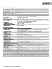
... standards Measurement accuracy +/- (voltage uncertainty + current uncertainty + current probe uncertainty) Frequency Measurement range Measurement source Measurement accuracy Power factor 42.5 to 69 Hz Same as PLL synchronization source ± 10 mHz (10 to 110 % of range, with... digit from the calculation of swell Measurement uncertainty Same as voltage dip Power Measurements Calculated per EN 61000-4-15:2003: 10 min (Pst), 2 h (Plt) 7 Fluke Corporation Fluke 1750 Three-Phase Power Recorder Transient voltage (impulse) Measurement type Full scale Sample resolution Measurement ...
... standards Measurement accuracy +/- (voltage uncertainty + current uncertainty + current probe uncertainty) Frequency Measurement range Measurement source Measurement accuracy Power factor 42.5 to 69 Hz Same as PLL synchronization source ± 10 mHz (10 to 110 % of range, with... digit from the calculation of swell Measurement uncertainty Same as voltage dip Power Measurements Calculated per EN 61000-4-15:2003: 10 min (Pst), 2 h (Plt) 7 Fluke Corporation Fluke 1750 Three-Phase Power Recorder Transient voltage (impulse) Measurement type Full scale Sample resolution Measurement ...

Fluke 1750 Calibration Manual
Page 12
... rms ± 10 % Overrange DC voltage: ± 1000 V + 10 % Overrange Voltage Crest Factor 3 or less Voltage Input Impedance 2 MΩ Current Measurement Range Depends on current probe used Current Crest Factor 4 or less Current Input Characteristics 2 V rms = full scale, 1 MΩ Input Impedance for ferro...12 cycles at 50 or 60 Hz respectively, as either wye or delta. 1750 Calibration Manual Synchronization and Sampling PLL-Synchronization Source The PLL synchronizes to the A-N voltage for wye power types, and to 100 % of current sensor range Transient Voltage (Impulse) Measurement...
... rms ± 10 % Overrange DC voltage: ± 1000 V + 10 % Overrange Voltage Crest Factor 3 or less Voltage Input Impedance 2 MΩ Current Measurement Range Depends on current probe used Current Crest Factor 4 or less Current Input Characteristics 2 V rms = full scale, 1 MΩ Input Impedance for ferro...12 cycles at 50 or 60 Hz respectively, as either wye or delta. 1750 Calibration Manual Synchronization and Sampling PLL-Synchronization Source The PLL synchronizes to the A-N voltage for wye power types, and to 100 % of current sensor range Transient Voltage (Impulse) Measurement...
Fluke 1750 Calibration Manual
Page 13
... synchronization source Measurement Accuracy 10 mHz (10 to 110 % of range, with sine wave) Reactive Power Accuracy 0.2 % reading ± 0.1 % full scale + current sensor accuracy Power Factor Measurement Range 1.000 (leading) to 0.000 to +1.000 (lagging) Measurement Accuracy 1 digit from... the calculation of each measured value (± 3 digits for total) Displacement Power Factor Measurement Method Calculated from the phase difference between voltage fundamental and current fundamental Measurement Range 1.000 (leading) to 0.000 to + ...
... synchronization source Measurement Accuracy 10 mHz (10 to 110 % of range, with sine wave) Reactive Power Accuracy 0.2 % reading ± 0.1 % full scale + current sensor accuracy Power Factor Measurement Range 1.000 (leading) to 0.000 to +1.000 (lagging) Measurement Accuracy 1 digit from... the calculation of each measured value (± 3 digits for total) Displacement Power Factor Measurement Method Calculated from the phase difference between voltage fundamental and current fundamental Measurement Range 1.000 (leading) to 0.000 to + ...

Fluke 1750 Calibration Manual
Page 22
..., I -Rogowski, and V-Wave channels are calibrated using 55 Hz sine wave signals to minimize 50 Hz or 60 Hz power line interference with the calibration measurements. For each of the calibration steps for calibrating the Recorder are qualified to the Recorder's ... are calibrated using known reference sources. During calibration, the Recorder measures the applied reference source, calculates correction factors, and stores the correction factors in the verification procedure. 1750 Calibration Manual Applie d Voltage [Vrms] 800 850 900 950 1000 Expected Reading [Vpk] 1131 1202 1273...
..., I -Rogowski, and V-Wave channels are calibrated using 55 Hz sine wave signals to minimize 50 Hz or 60 Hz power line interference with the calibration measurements. For each of the calibration steps for calibrating the Recorder are qualified to the Recorder's ... are calibrated using known reference sources. During calibration, the Recorder measures the applied reference source, calculates correction factors, and stores the correction factors in the verification procedure. 1750 Calibration Manual Applie d Voltage [Vrms] 800 850 900 950 1000 Expected Reading [Vpk] 1131 1202 1273...

Fluke 1750 Operators Manual
Page 51
... the voltage and current to a convenient level for measuring instruments. Azd134.bmp Assign Recorder Name and Password Use this menu to add a ratio factor to the voltage or current input on each case if there is intended to be used for the Recorder. Changing the first "1" in each...which Recorder is designed to establish a password for sensing low levels of current to represent the much higher levels on a medium-voltage network. Power Recorder Setting Up the Recorder Azd133.bmp Setting the Volts and Current Ratio Use this feature to assign a name identifier to the Recorder and ...
... the voltage and current to a convenient level for measuring instruments. Azd134.bmp Assign Recorder Name and Password Use this menu to add a ratio factor to the voltage or current input on each case if there is intended to be used for the Recorder. Changing the first "1" in each...which Recorder is designed to establish a password for sensing low levels of current to represent the much higher levels on a medium-voltage network. Power Recorder Setting Up the Recorder Azd133.bmp Setting the Volts and Current Ratio Use this feature to assign a name identifier to the Recorder and ...

Fluke 1750 Operators Manual
Page 58
1750 Operators Manual Specifications for the System: Recorder and Power Analyze Software General Specifications Power Quality Measurement Standards Conformance IEC 61000-2-4:2002 Class 1, IEC 61000-4-30, IEEE519, IEEE1159, IEEE1459, IEC 61557-12:2008, and EN50160 Clock/Calendar ... 2 GB Maximum Recording Period At least 31 days Measurement Time Control Automatic Maximum Number of Events Limited only by the size of the internal memory. Power Requirements 100 to 240 V rms ± 10 %, 47-63 Hz, 40 W Operating Time During Interruptions (internal UPS operation 5 minutes per interruption, ...
1750 Operators Manual Specifications for the System: Recorder and Power Analyze Software General Specifications Power Quality Measurement Standards Conformance IEC 61000-2-4:2002 Class 1, IEC 61000-4-30, IEEE519, IEEE1159, IEEE1459, IEC 61557-12:2008, and EN50160 Clock/Calendar ... 2 GB Maximum Recording Period At least 31 days Measurement Time Control Automatic Maximum Number of Events Limited only by the size of the internal memory. Power Requirements 100 to 240 V rms ± 10 %, 47-63 Hz, 40 W Operating Time During Interruptions (internal UPS operation 5 minutes per interruption, ...

Fluke 1750 Operators Manual
Page 60
1750 Operators Manual Power Factor Measurement Range 1.000 (leading) to 0.000 to +1.000 (lagging) Measurement Accuracy 1 digit from the calculation of each measured value (± 3 digits for total) Displacement Power Factor Measurement Method Calculated from the phase difference between voltage fundamental and ...50th orders: ± 1 % reading ± 0.3 % full scale (current sensor accuracy must be included for current and power) Measurement Method IEC 61000-4-7:2002 Inter-harmonic Voltage and Current (Intermediate Harmonics) Analysis Window rectangular Analysis Orders 0.5 to 49.5th ...
1750 Operators Manual Power Factor Measurement Range 1.000 (leading) to 0.000 to +1.000 (lagging) Measurement Accuracy 1 digit from the calculation of each measured value (± 3 digits for total) Displacement Power Factor Measurement Method Calculated from the phase difference between voltage fundamental and ...50th orders: ± 1 % reading ± 0.3 % full scale (current sensor accuracy must be included for current and power) Measurement Method IEC 61000-4-7:2002 Inter-harmonic Voltage and Current (Intermediate Harmonics) Analysis Window rectangular Analysis Orders 0.5 to 49.5th ...


