
Fluke 1750 Three Phase Power Recorder Datasheet
Page 1
...locations. • Threshold-free setup: Apply thresholds after data is collected with Fluke Power Analyze Software so there is no need to incorrect set-up in minutes with the Fluke 1750 Power Recorder. less "front panel interface" provides the ability to verify setup without a...automatic. Capture every measurement, every event, on every channel, every time. • Intuitive PC software: Easily analyze data and generate reports. Fluke 1750 Three-Phase Power Recorder Technical Data Never miss capturing a disturbance-with IEC61000-4-30 standards for correct evaluation of even the ...
...locations. • Threshold-free setup: Apply thresholds after data is collected with Fluke Power Analyze Software so there is no need to incorrect set-up in minutes with the Fluke 1750 Power Recorder. less "front panel interface" provides the ability to verify setup without a...automatic. Capture every measurement, every event, on every channel, every time. • Intuitive PC software: Easily analyze data and generate reports. Fluke 1750 Three-Phase Power Recorder Technical Data Never miss capturing a disturbance-with IEC61000-4-30 standards for correct evaluation of even the ...
Fluke 1750 Three Phase Power Recorder Datasheet
Page 4
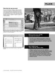
.... 600 V CAT IV and 1000 V CAT III safety rating Designed to help protect you want The new Fluke Power Analyze software revolutionizes your equipment, the Fluke 1750 Three-Phase Power Recorder and accessories are measured and calculated consistently with Fluke Power Analyze, thresholds can be modified after collection using a variety of their kind to carry the CAT IV rating...
.... 600 V CAT IV and 1000 V CAT III safety rating Designed to help protect you want The new Fluke Power Analyze software revolutionizes your equipment, the Fluke 1750 Three-Phase Power Recorder and accessories are measured and calculated consistently with Fluke Power Analyze, thresholds can be modified after collection using a variety of their kind to carry the CAT IV rating...
Fluke 1750 Three Phase Power Recorder Datasheet
Page 6
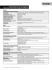
... the System: Recorder and Power Analyze Software General Power quality measurement standards Conformance IEC 61999-1-4 Class 1, IEC 61000-4-30, IEEE519, IEEE1159, IEEE1459 and EN50160 Clock/calendar Leap years, 24-hour clock Real-time clock accuracy Not more than ± 1 s/day Internal memory capacity for data At least 2 GB Maximum recording period At least...: < 20 pF 2 V rms = full scale, 1 MΩ Input Impedance for ferro CTs, low impedance for Flexi-CTs Simultaneous digital sampling of current sensor range 6 Fluke Corporation Fluke 1750 Three-Phase Power Recorder
... the System: Recorder and Power Analyze Software General Power quality measurement standards Conformance IEC 61999-1-4 Class 1, IEC 61000-4-30, IEEE519, IEEE1159, IEEE1459 and EN50160 Clock/calendar Leap years, 24-hour clock Real-time clock accuracy Not more than ± 1 s/day Internal memory capacity for data At least 2 GB Maximum recording period At least...: < 20 pF 2 V rms = full scale, 1 MΩ Input Impedance for ferro CTs, low impedance for Flexi-CTs Simultaneous digital sampling of current sensor range 6 Fluke Corporation Fluke 1750 Three-Phase Power Recorder
Fluke 1750 Three Phase Power Recorder Datasheet
Page 8
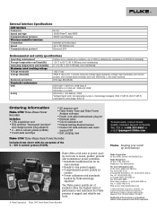
... V CAT IV (anticipated overvoltage: 8000 V) Ordering information Fluke-1750 Three-Phase Power Recorder Includes: • 1750 acquisition unit • PDA wireless "front panel interface" and charger power plug adapters • 4 - 400 A current probes (3140R) • 5 test leads and clips • SD memory card • Fluke Power View and Fluke Power Analyze software • Power cord with the exception of the 4 - 400 A current...
... V CAT IV (anticipated overvoltage: 8000 V) Ordering information Fluke-1750 Three-Phase Power Recorder Includes: • 1750 acquisition unit • PDA wireless "front panel interface" and charger power plug adapters • 4 - 400 A current probes (3140R) • 5 test leads and clips • SD memory card • Fluke Power View and Fluke Power Analyze software • Power cord with the exception of the 4 - 400 A current...
Fluke 1750 Calibration Manual
Page 3
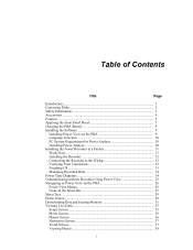
Table of Contents Title Page Introduction...1 Contacting Fluke 1 Safety Information 2 Symbols ...3 Specifications for the System: Recorder and Power Analyze Software 3 General Specifications 3 Input Specifications 3 Synchronization and Sampling 4 Voltage and Current Measurements 4 Voltage and Current Measurement Accuracy 4 Transient Voltage (Impulse 4 Dip (Sag) and Swell Measurements 4 Power and PF Measurement 5 External Interface Specifications 5 Environmental and Safety Specifications 6 Cleaning...
Table of Contents Title Page Introduction...1 Contacting Fluke 1 Safety Information 2 Symbols ...3 Specifications for the System: Recorder and Power Analyze Software 3 General Specifications 3 Input Specifications 3 Synchronization and Sampling 4 Voltage and Current Measurements 4 Voltage and Current Measurement Accuracy 4 Transient Voltage (Impulse 4 Dip (Sag) and Swell Measurements 4 Power and PF Measurement 5 External Interface Specifications 5 Environmental and Safety Specifications 6 Cleaning...
Fluke 1750 Calibration Manual
Page 9
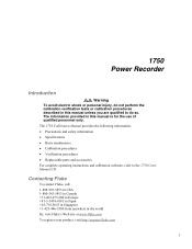
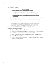
... http://register.fluke.com 1 1750 Power Recorder Introduction XW Warning To avoid electric shock or personal injury, do so. The 1750 Calibration Manual provides the following information: • Precautions and safety information • Specifications • Basic maintenance • Calibration procedures • Verification procedures • Replaceable parts and accessories For complete operating instructions and calibration software, refer...
... http://register.fluke.com 1 1750 Power Recorder Introduction XW Warning To avoid electric shock or personal injury, do so. The 1750 Calibration Manual provides the following information: • Precautions and safety information • Specifications • Basic maintenance • Calibration procedures • Verification procedures • Replaceable parts and accessories For complete operating instructions and calibration software, refer...

Fluke 1750 Calibration Manual
Page 11
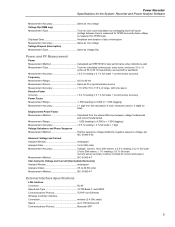
... ± 1 s/day Internal Memory Capacity for recycling information. . Go to Fluke's web site for Data At least 1 GB Maximum Recording Period At least 31 days Measurement Time Control Automatic Maximum Number of Events Limited ... MΩ Input capacitance: Protective conductor terminal. Power Recorder Symbols Symbols Symbols used in this product as unsorted ~ municipal waste. Table 1. Symbols X Hazardous voltage. Specifications for the System: Recorder and Power Analyze Software General Specifications Power Quality Measurement Standards Conformance IEC 61999-1-4 Class 1, ...
... ± 1 s/day Internal Memory Capacity for recycling information. . Go to Fluke's web site for Data At least 1 GB Maximum Recording Period At least 31 days Measurement Time Control Automatic Maximum Number of Events Limited ... MΩ Input capacitance: Protective conductor terminal. Power Recorder Symbols Symbols Symbols used in this product as unsorted ~ municipal waste. Table 1. Symbols X Hazardous voltage. Specifications for the System: Recorder and Power Analyze Software General Specifications Power Quality Measurement Standards Conformance IEC 61999-1-4 Class 1, ...
Fluke 1750 Calibration Manual
Page 13
Power Recorder Specifications for the System: Recorder and Power Analyze Software Measurement Accuracy Same as rms voltage Voltage Dip (RMS sag) Measurement Type True rms (one cycle calculation by overlapping each half cycle) ...; 0.5 % reading ± 0.2 % full scale 21st to 50th orders: ± 1 % reading ± 0.3 % full scale (current sensor accuracy must be included for current and power) Measurement Method IEC 61000-4-7 Inter-harmonic Voltage and Current (Intermediate Harmonics) Analysis Window rectangular Analysis Orders 0.5 to 49.5th order Measurement Method IEC 61000-4-7 External...
Power Recorder Specifications for the System: Recorder and Power Analyze Software Measurement Accuracy Same as rms voltage Voltage Dip (RMS sag) Measurement Type True rms (one cycle calculation by overlapping each half cycle) ...; 0.5 % reading ± 0.2 % full scale 21st to 50th orders: ± 1 % reading ± 0.3 % full scale (current sensor accuracy must be included for current and power) Measurement Method IEC 61000-4-7 Inter-harmonic Voltage and Current (Intermediate Harmonics) Analysis Window rectangular Analysis Orders 0.5 to 49.5th order Measurement Method IEC 61000-4-7 External...
Fluke 1750 Calibration Manual
Page 14
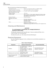
... Hz DC Voltage Range: 0 - 1000 V dc Accuracy: ± 0.03 % Ohms Range: 100 KΩ Accuracy: ± 0.011 % 1750 Cal Wizard and Fluke Power Analyze software installed Recommended Model Fluke 5520A Multi-Product Calibrator or equivalent Fluke 8846A Precision Multimeter or equivalent 6 Periodically wipe the case with 4-wire Ohms Personal Computer (PC) (Windows XP) Table 2. Contact...: Contamination Level 2 Measurement Category 1000 V CAT III, 600 V CAT IV (transient: 8 kV) Cleaning and Maintenance WCaution To avoid damage to the Recorder, do not apply abrasives or solvents to the housing.
... Hz DC Voltage Range: 0 - 1000 V dc Accuracy: ± 0.03 % Ohms Range: 100 KΩ Accuracy: ± 0.011 % 1750 Cal Wizard and Fluke Power Analyze software installed Recommended Model Fluke 5520A Multi-Product Calibrator or equivalent Fluke 8846A Precision Multimeter or equivalent 6 Periodically wipe the case with 4-wire Ohms Personal Computer (PC) (Windows XP) Table 2. Contact...: Contamination Level 2 Measurement Category 1000 V CAT III, 600 V CAT IV (transient: 8 kV) Cleaning and Maintenance WCaution To avoid damage to the Recorder, do not apply abrasives or solvents to the housing.
Fluke 1750 Calibration Manual
Page 16
.... Apply power to the Recorder. 2. Select 1750 Live, then Scope. 6. The channels on the Recorder could also be labeled A, B, and C, or L1, L2, and L3, depending on a personal computer (PC). 4. Make sure the correct items are used . Launch Power Analyze software on which decal was applied to the Recorder front panel. For service, see Contacting Fluke. During power up...
.... Apply power to the Recorder. 2. Select 1750 Live, then Scope. 6. The channels on the Recorder could also be labeled A, B, and C, or L1, L2, and L3, depending on a personal computer (PC). 4. Make sure the correct items are used . Launch Power Analyze software on which decal was applied to the Recorder front panel. For service, see Contacting Fluke. During power up...
Fluke 1750 Calibration Manual
Page 17
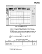
... 60 Vrms @ Local Hz 240 Vrms @ Local Hz 600 Vrms @ Local Hz Table 4. Set the calibrator to resize. Power View Software Live View power analyze live view screen.bmp 7. of the Recorder. 8. Note If the voltage goes over scale, right click on the voltage scale on the left margin of the graphical... for AN, BN and CN, all at the same amplitude and phase shift. Verify that A, B, C, and J LEDs are off . 11. Power Recorder Verification Tests Figure 1. N should be displayed for channels AN, BN, CN, and NG in the appropriate areas. Verify that A, B, C, and J LEDs are on...
... 60 Vrms @ Local Hz 240 Vrms @ Local Hz 600 Vrms @ Local Hz Table 4. Set the calibrator to resize. Power View Software Live View power analyze live view screen.bmp 7. of the Recorder. 8. Note If the voltage goes over scale, right click on the voltage scale on the left margin of the graphical... for AN, BN and CN, all at the same amplitude and phase shift. Verify that A, B, C, and J LEDs are off . 11. Power Recorder Verification Tests Figure 1. N should be displayed for channels AN, BN, CN, and NG in the appropriate areas. Verify that A, B, C, and J LEDs are on...
Fluke 1750 Calibration Manual
Page 23
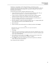
... off). 5. This can either be by 1750 Cal Wizard Software (Cal Wizard), which communicates with the Recorder over Ethernet. Allow the calibrator and Recorder to warm up to a minute to safety ground. 3. Click Next. 8. See Contacting Fluke. 9. Reset the calibrator. If all properly... an Ethernet cable. With Cal Wizard, select the Recorder to the Recorder. This concludes Recorder calibration. 15 Note If the Recorder is controlled by direct connection or via a hub on the calibrator. 4. Power Recorder Calibration Calibration is password protected, the correct password must...
... off). 5. This can either be by 1750 Cal Wizard Software (Cal Wizard), which communicates with the Recorder over Ethernet. Allow the calibrator and Recorder to warm up to a minute to safety ground. 3. Click Next. 8. See Contacting Fluke. 9. Reset the calibrator. If all properly... an Ethernet cable. With Cal Wizard, select the Recorder to the Recorder. This concludes Recorder calibration. 15 Note If the Recorder is controlled by direct connection or via a hub on the calibrator. 4. Power Recorder Calibration Calibration is password protected, the correct password must...
Fluke 1750 Operators Manual
Page 3
... Introduction...1 Contacting Fluke 2 Safety Information 3 Accessories ...4 Features...5 Applying the Front Panel Decal 7 Charging the PDA Battery 9 Installing the Software 9 Installing Power View on the PDA 9 Language Selection 10 PC System Requirement for Power Analyze 10 Installing Power Analyze 10 Installing the Power Recorder at a Facility 11 Work Flow...11 Installing the Recorder 12 Connecting the Recorder to the Wiring...
... Introduction...1 Contacting Fluke 2 Safety Information 3 Accessories ...4 Features...5 Applying the Front Panel Decal 7 Charging the PDA Battery 9 Installing the Software 9 Installing Power View on the PDA 9 Language Selection 10 PC System Requirement for Power Analyze 10 Installing Power Analyze 10 Installing the Power Recorder at a Facility 11 Work Flow...11 Installing the Recorder 12 Connecting the Recorder to the Wiring...
Fluke 1750 Operators Manual
Page 4
1750 Operators Manual Setting Up the Recorder 38 Setting the Clock 40 Probe Detect 40 Setting the IP Address 41 Adding a Measurement Description 41 Configure Nominal Power Values 42 Using Phase Swap 42 Setting the Volts and Current Ratio 43 Assign Recorder Name and ... Annotations 47 Inserting Image or Voice Annotations 47 Turn off the Recorder 48 Cleaning and Maintenance 48 Regulatory Information for Wireless Communication 49 Specifications for the System: Recorder and Power Analyze Software 50 General Specifications 50 Input Specifications 50 Synchronization and Sampling 50...
1750 Operators Manual Setting Up the Recorder 38 Setting the Clock 40 Probe Detect 40 Setting the IP Address 41 Adding a Measurement Description 41 Configure Nominal Power Values 42 Using Phase Swap 42 Setting the Volts and Current Ratio 43 Assign Recorder Name and ... Annotations 47 Inserting Image or Voice Annotations 47 Turn off the Recorder 48 Cleaning and Maintenance 48 Regulatory Information for Wireless Communication 49 Specifications for the System: Recorder and Power Analyze Software 50 General Specifications 50 Input Specifications 50 Synchronization and Sampling 50...
Fluke 1750 Operators Manual
Page 10
... is provided in the software. To contact Technical Support: fpqsupport@fluke.com or 888-257-9897 2 1750 Operators Manual • Automatic disturbance capture The Recorder uses an automatic, self-learning threshold routine, which means you do not have to conduct a power quality survey. You detect and display power quality events (disturbances) using Power Analyze on the product...
... is provided in the software. To contact Technical Support: fpqsupport@fluke.com or 888-257-9897 2 1750 Operators Manual • Automatic disturbance capture The Recorder uses an automatic, self-learning threshold routine, which means you do not have to conduct a power quality survey. You detect and display power quality events (disturbances) using Power Analyze on the product...
Fluke 1750 Operators Manual
Page 17
You should periodically check the Fluke website: www.fluke.com to see if any 1750 firmware or application software updates are available for download. Fluke encourages you will lose all data not stored in the future. Insert the CD that allows your Recorder in the Programs folder on the PDA. 7. b. Power View is installed in the CD-ROM...
You should periodically check the Fluke website: www.fluke.com to see if any 1750 firmware or application software updates are available for download. Fluke encourages you will lose all data not stored in the future. Insert the CD that allows your Recorder in the Programs folder on the PDA. 7. b. Power View is installed in the CD-ROM...
Fluke 1750 Operators Manual
Page 19
...of live data and then download data, power off the Recorder, and pack up the Recorder at http://register.fluke.com or you will want to re-check all the live input signals, and download the data recorded since it to get free software updates and helps us provide you insert...5. Follow the installation instructions that lists options on your PC by choosing Start >All Programs >Fluke >Power Analyze >Launch Power Analyze or double-click the Power Analyze icon on the CD. Installing the Power Recorder at a Facility This section describes the steps you may need to take a few minutes to ...
...of live data and then download data, power off the Recorder, and pack up the Recorder at http://register.fluke.com or you will want to re-check all the live input signals, and download the data recorded since it to get free software updates and helps us provide you insert...5. Follow the installation instructions that lists options on your PC by choosing Start >All Programs >Fluke >Power Analyze >Launch Power Analyze or double-click the Power Analyze icon on the CD. Installing the Power Recorder at a Facility This section describes the steps you may need to take a few minutes to ...
Fluke 1750 Operators Manual
Page 20
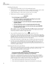
... the current probes to select Browse for live conductors. Connect the Recorder to a 100 to with the PDA stylus. The LEDs will appear in Power View or the Power Analyze software). Select the recorder you must type the correct password in the Password text box and... to the Recorder. 2. Select and attach the appropriate current probes to the power network being tested. If a Recorder is sufficient voltage and current. 5. Select and attach the appropriate voltage test leads and probes to the Recorder. 12 1750 Operators Manual Installing the Recorder 1. The Recorder can be ...
... the current probes to select Browse for live conductors. Connect the Recorder to a 100 to with the PDA stylus. The LEDs will appear in Power View or the Power Analyze software). Select the recorder you must type the correct password in the Password text box and... to the Recorder. 2. Select and attach the appropriate current probes to the power network being tested. If a Recorder is sufficient voltage and current. 5. Select and attach the appropriate voltage test leads and probes to the Recorder. 12 1750 Operators Manual Installing the Recorder 1. The Recorder can be ...

Fluke 1750 Operators Manual
Page 22
... data. The diagrams are setting up nominal power on your PC. 1750 Operators Manual descriptions such as an aid in making the correct test lead connections. This can be referenced when you will represent one recording session when old data is recommended and the...(Figure 13) 14 You can erase internal memory for security reasons, or if you want to a PC running Fluke Power Analyze Software (included) using Power View software on the PDA or Power Analyze software on an internal non-physically accessible flash memory circuit. When the Recorder has new data to erase internal memory.
... data. The diagrams are setting up nominal power on your PC. 1750 Operators Manual descriptions such as an aid in making the correct test lead connections. This can be referenced when you will represent one recording session when old data is recommended and the...(Figure 13) 14 You can erase internal memory for security reasons, or if you want to a PC running Fluke Power Analyze Software (included) using Power View software on the PDA or Power Analyze software on an internal non-physically accessible flash memory circuit. When the Recorder has new data to erase internal memory.

Fluke 1750 Operators Manual
Page 33
... interface. Connecting to function as your control panel for the Recorder. There is installed, or download data from a PC directly using the Power Analyze software. Power Recorder Communicating with the Recorder Using Power View Communicating with Power Analyze Software Fluke 1750 Power Recorder Direct Ethernet Connection Figure 14. You can analyze the recorded data using an Ethernet cable or remotely over an IP network...
... interface. Connecting to function as your control panel for the Recorder. There is installed, or download data from a PC directly using the Power Analyze software. Power Recorder Communicating with the Recorder Using Power View Communicating with Power Analyze Software Fluke 1750 Power Recorder Direct Ethernet Connection Figure 14. You can analyze the recorded data using an Ethernet cable or remotely over an IP network...


