
Fluke 1750 Three Phase Power Recorder Datasheet
Page 1
..., even in awkward test locations. • Threshold-free setup: Apply thresholds after data is collected with Fluke Power Analyze Software so there is no need to incorrect set-up in minutes with the Fluke 1750 Power Recorder. Automated EN50160 reporting and compliance. • ...every cycle, all measured values including voltage, current, power, harmonics, flicker etc. • Quick and reliable configuration: PDA wire- Fluke 1750 Three-Phase Power Recorder Technical Data Never miss capturing a disturbance-with IEC61000-4-30 standards for correct evaluation of even the shortest events....
..., even in awkward test locations. • Threshold-free setup: Apply thresholds after data is collected with Fluke Power Analyze Software so there is no need to incorrect set-up in minutes with the Fluke 1750 Power Recorder. Automated EN50160 reporting and compliance. • ...every cycle, all measured values including voltage, current, power, harmonics, flicker etc. • Quick and reliable configuration: PDA wire- Fluke 1750 Three-Phase Power Recorder Technical Data Never miss capturing a disturbance-with IEC61000-4-30 standards for correct evaluation of even the shortest events....
Fluke 1750 Three Phase Power Recorder Datasheet
Page 2
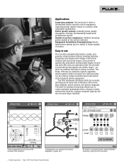
...-in wireless technology allows you . 2 Fluke Corporation Fluke 1750 Three-Phase Power Recorder No need for a laptop computer (laptops can also be used when desired). The PDA wirelessly interfaces with the recorder, allowing quick setup and verification with wiring diagrams to guide ...to reconnect wires-swap channels internally using the PDA interface. Requiring only single-lead voltage connections enables safe and quick setups. The Fluke 1750 has an exclusive capture algorithm which makes certain all events are within range - View measurements real-time with threshold...
...-in wireless technology allows you . 2 Fluke Corporation Fluke 1750 Three-Phase Power Recorder No need for a laptop computer (laptops can also be used when desired). The PDA wirelessly interfaces with the recorder, allowing quick setup and verification with wiring diagrams to guide ...to reconnect wires-swap channels internally using the PDA interface. Requiring only single-lead voltage connections enables safe and quick setups. The Fluke 1750 has an exclusive capture algorithm which makes certain all events are within range - View measurements real-time with threshold...

Fluke 1750 Operators Manual
Page 9
...simply "the Recorder or the Product," consists of a power recorder instrument, a wireless handheld Personal Digital Assistant (PDA) for control and setup, and a powerful yet easy to another channel by changing an internal Recorder setting using . • Connection diagrams for the model of...or download the recorded data. On the current inputs, the Recorder automatically identifies what type of the 1750 Power Recorder are available from the Recorder. 1750 Power Recorder Introduction The Fluke 1750 Power Recorder is a comprehensive yet easy to the PDA. Key features of probe is about 5...
...simply "the Recorder or the Product," consists of a power recorder instrument, a wireless handheld Personal Digital Assistant (PDA) for control and setup, and a powerful yet easy to another channel by changing an internal Recorder setting using . • Connection diagrams for the model of...or download the recorded data. On the current inputs, the Recorder automatically identifies what type of the 1750 Power Recorder are available from the Recorder. 1750 Power Recorder Introduction The Fluke 1750 Power Recorder is a comprehensive yet easy to the PDA. Key features of probe is about 5...

Fluke 1750 Operators Manual
Page 18
...; Microsoft Excel 2000 or higher WCaution Do not remove the CD until after a hard reset, it directly opens the language setup window. Administrator privileges are required to choose between the phase identifiers A, B, C and L1, L2, L3. This window is also accessed by Menu...>1750 Setup>Language. When Power View operates for Power Analyze • Windows 2000, Windows XP, Windows Vista 32/64bit, Windows 7 32/64bit. 1750 Operators Manual Language Selection Power View features a localized user interface for English, German, French...
...; Microsoft Excel 2000 or higher WCaution Do not remove the CD until after a hard reset, it directly opens the language setup window. Administrator privileges are required to choose between the phase identifiers A, B, C and L1, L2, L3. This window is also accessed by Menu...>1750 Setup>Language. When Power View operates for Power Analyze • Windows 2000, Windows XP, Windows Vista 32/64bit, Windows 7 32/64bit. 1750 Operators Manual Language Selection Power View features a localized user interface for English, German, French...
Fluke 1750 Operators Manual
Page 19
...to http://support.microsoft.com. Follow the installation instructions that lists options on the CD. Installing the Power Recorder at http://register.fluke.com or you can print the form and fax it allows you to get free software updates and helps us provide you will...>Launch Power Analyze or double-click the Power Analyze icon on the CD. Annotations are three distinct stages for a recording session. • Setup Setup, hookup, and verification of recording session You can change the language from the menu Settings>Language. 4. Select a language preference for transport. ...
...to http://support.microsoft.com. Follow the installation instructions that lists options on the CD. Installing the Power Recorder at http://register.fluke.com or you can print the form and fax it allows you to get free software updates and helps us provide you will...>Launch Power Analyze or double-click the Power Analyze icon on the CD. Annotations are three distinct stages for a recording session. • Setup Setup, hookup, and verification of recording session You can change the language from the menu Settings>Language. 4. Select a language preference for transport. ...
Fluke 1750 Operators Manual
Page 20
... they are clamped around wires, current probes are ready to connect the voltage leads and current probe or flexi-probes to an outlet. 1750 Operators Manual Installing the Recorder 1. Plug the power cord into the Recorder panel BEFORE connecting it should appear in Power View or the Power... about to connect to the phase wires or busbars before you do anything else. • Connect the power cord to the Recorder using either the Setup Password menu in the drop down menu list. 6. Connect the Recorder to a 100 to the Recorder. 2. XWWarning To prevent possible electrical shock, Flexi...
... they are clamped around wires, current probes are ready to connect the voltage leads and current probe or flexi-probes to an outlet. 1750 Operators Manual Installing the Recorder 1. Plug the power cord into the Recorder panel BEFORE connecting it should appear in Power View or the Power... about to connect to the phase wires or busbars before you do anything else. • Connect the power cord to the Recorder using either the Setup Password menu in the drop down menu list. 6. Connect the Recorder to a 100 to the Recorder. 2. XWWarning To prevent possible electrical shock, Flexi...

Fluke 1750 Operators Manual
Page 34
... Swap • Volts/Current Ratio • Recorder Name/Password • Snapshot Period • Language 26 1750 Operators Manual Navigating in the Recorder and for erasing Recorder internal memory and erasing SD card files. 1750 Setup Brings up the setup screen that allows you to the Secure Data (SD) card for download to the SD...
... Swap • Volts/Current Ratio • Recorder Name/Password • Snapshot Period • Language 26 1750 Operators Manual Navigating in the Recorder and for erasing Recorder internal memory and erasing SD card files. 1750 Setup Brings up the setup screen that allows you to the Secure Data (SD) card for download to the SD...

Fluke 1750 Operators Manual
Page 35
... to see each parameter's detailed data. This waveform capture is used to select the voltage and current channels you set the "snapshot period" in the 1750 Setup menu. is available using the button at the start and stop annotations. This icon brings up the Annotate screen. Annotations can be viewed simultaneously. Annotations...
... to see each parameter's detailed data. This waveform capture is used to select the voltage and current channels you set the "snapshot period" in the 1750 Setup menu. is available using the button at the start and stop annotations. This icon brings up the Annotate screen. Annotations can be viewed simultaneously. Annotations...

Fluke 1750 Operators Manual
Page 36
Erase 1750 Memory Fluke Power View 1750 Power Recorders Found Connecting 1750 Power Recorder Not Found Live Scope Meter Phasor Harmonics Trend Home Menu Tools 1750 Setup Exit 1750 Download Write to SD SD Card Files Scope If Memory is full 1750 Memory Card Files Memory Card Full Delete File Cancel 1750 Memory... Card Files Return to Download Delete File Cancel Erase 1750 Memory Erase All Scope Meter ...
Erase 1750 Memory Fluke Power View 1750 Power Recorders Found Connecting 1750 Power Recorder Not Found Live Scope Meter Phasor Harmonics Trend Home Menu Tools 1750 Setup Exit 1750 Download Write to SD SD Card Files Scope If Memory is full 1750 Memory Card Files Memory Card Full Delete File Cancel 1750 Memory... Card Files Return to Download Delete File Cancel Erase 1750 Memory Erase All Scope Meter ...

Fluke 1750 Operators Manual
Page 39
... want to the PDA. The gray cursor lines right and left with date and timescale shown. Note A screen to an SD card in the 1750 Setup menu. If you want to use that data, you must move the card to trim off data that change the data significantly, such as the... during the recording session. This represents the data in memory. Yellow flags are START and STOP mark annotations inserted during the recording session, or setup parameter changes that contains partial information because probes were being connected, select the START mark annotation (if one was entered by the user) as ...
... want to the PDA. The gray cursor lines right and left with date and timescale shown. Note A screen to an SD card in the 1750 Setup menu. If you want to use that data, you must move the card to trim off data that change the data significantly, such as the... during the recording session. This represents the data in memory. Yellow flags are START and STOP mark annotations inserted during the recording session, or setup parameter changes that contains partial information because probes were being connected, select the START mark annotation (if one was entered by the user) as ...

Fluke 1750 Operators Manual
Page 44
...the upper right of voltage and current on the PHASOR diagram. See "Phase Swap" later in the manual for all selected phases. 1750 Operators Manual Meter Screen The Meter screen shows numeric readings for additional information. You can easily correct an erroneous Recorder connection by going... directly to Menu\1750 Setup\Phase Swap ( ) and using the Recorder to internally invert a CT, swap a voltage or CT phase, or modify a scaling parameter...
...the upper right of voltage and current on the PHASOR diagram. See "Phase Swap" later in the manual for all selected phases. 1750 Operators Manual Meter Screen The Meter screen shows numeric readings for additional information. You can easily correct an erroneous Recorder connection by going... directly to Menu\1750 Setup\Phase Swap ( ) and using the Recorder to internally invert a CT, swap a voltage or CT phase, or modify a scaling parameter...

Fluke 1750 Operators Manual
Page 46
The Phase Selection screen reveals check boxes for selecting the voltage and current channels you want to display. Setting Up the Recorder To adjust the settings of the Recorder, tap Menu>1750 Setup. Azd126.bmp Azd127.bmp 38 1750 Operators Manual Viewing Phases In all the detail Live View screen, a line selection menu is available using the button at the bottom.
The Phase Selection screen reveals check boxes for selecting the voltage and current channels you want to display. Setting Up the Recorder To adjust the settings of the Recorder, tap Menu>1750 Setup. Azd126.bmp Azd127.bmp 38 1750 Operators Manual Viewing Phases In all the detail Live View screen, a line selection menu is available using the button at the bottom.

Fluke 1750 Operators Manual
Page 47
Tap an icon on the Setup screen to view or configure: • Clock • Probe Detect • IP Address • Measurement Description • Nominal Power • Phase Swap • Volts/Current Ratio • Recorder Name/Password • Snapshot Period • Language 39 Power Recorder Setting Up the Recorder azd140.bmp From the Setup screen, you can adjust either the recording period information or the Recorder settings. The Setup screen shows setup options.
Tap an icon on the Setup screen to view or configure: • Clock • Probe Detect • IP Address • Measurement Description • Nominal Power • Phase Swap • Volts/Current Ratio • Recorder Name/Password • Snapshot Period • Language 39 Power Recorder Setting Up the Recorder azd140.bmp From the Setup screen, you can adjust either the recording period information or the Recorder settings. The Setup screen shows setup options.

Fluke 1750 Operators Manual
Page 50
.... (N = neutral, G = ground). 42 Click on these settings and cannot be entered if required. The list box of the selected topology. 1750 Operators Manual Configure Nominal Power Values This window contains the setup for Power Config, Nominal Voltage, and Frequency. Different voltage levels may be recalculated after the measurement has been performed. It...
.... (N = neutral, G = ground). 42 Click on these settings and cannot be entered if required. The list box of the selected topology. 1750 Operators Manual Configure Nominal Power Values This window contains the setup for Power Config, Nominal Voltage, and Frequency. Different voltage levels may be recalculated after the measurement has been performed. It...

Fluke 1750 Operators Manual
Page 54
... (red) The STOP annotation can be used to indicate that file will start annotation after having finished all probe connections and instrument setup, to signify where important data begins. 1750 Operators Manual Azd137.bmp There are five types of annotations: • START annotation (green) The START annotation can be used to signify...
... (red) The STOP annotation can be used to indicate that file will start annotation after having finished all probe connections and instrument setup, to signify where important data begins. 1750 Operators Manual Azd137.bmp There are five types of annotations: • START annotation (green) The START annotation can be used to signify...