
Fluke 1750 Three Phase Power Recorder Datasheet
Page 1
Fluke 1750 Three-Phase Power Recorder Technical Data Never miss capturing a disturbance-with the Fluke 1750 Power Recorder. less "front panel interface" provides the ability to verify setup without a laptop along with a window into your installation or distribution system. • Power quality that meets the standard: All ...set-up in awkward test locations. • Threshold-free setup: Apply thresholds after data is collected with Fluke Power Analyze Software so there is recording, even in minutes with the wireless PDA or PC when connections are not correct. • Measure every...
Fluke 1750 Three-Phase Power Recorder Technical Data Never miss capturing a disturbance-with the Fluke 1750 Power Recorder. less "front panel interface" provides the ability to verify setup without a laptop along with a window into your installation or distribution system. • Power quality that meets the standard: All ...set-up in awkward test locations. • Threshold-free setup: Apply thresholds after data is collected with Fluke Power Analyze Software so there is recording, even in minutes with the wireless PDA or PC when connections are not correct. • Measure every...
Fluke 1750 Three Phase Power Recorder Datasheet
Page 2
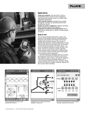
... displays, meter screens, and phasor diagrams. The built-in wireless technology allows you . 2 Fluke Corporation Fluke 1750 Three-Phase Power Recorder No need for a laptop computer (laptops can also be used when desired). monitor critical equipment, capturing power quality events to correlate with equipment malfunction Power quality surveys: Quantify power quality throughout a facility, documenting results with wireless PDA interface.
... displays, meter screens, and phasor diagrams. The built-in wireless technology allows you . 2 Fluke Corporation Fluke 1750 Three-Phase Power Recorder No need for a laptop computer (laptops can also be used when desired). monitor critical equipment, capturing power quality events to correlate with equipment malfunction Power quality surveys: Quantify power quality throughout a facility, documenting results with wireless PDA interface.
Fluke 1750 Three Phase Power Recorder Datasheet
Page 3
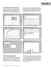
...to the 50th harmonic. When periodic analysis of power quality, harmonics, power and energy. Full-featured power meter display for the EN50160 report are easily customized. Voice, data, and picture annotations can be recorded! card without compression or overwriting. Events can be...or load changes were made via one graph. Comprehensive power system data Every cycle on every channel is simultaneously sampled providing complete analysis of the waveform may be made . 3 Fluke Corporation Fluke 1750 Three-Phase Power Recorder Data is retrieved via the PDA to flag in ...
...to the 50th harmonic. When periodic analysis of power quality, harmonics, power and energy. Full-featured power meter display for the EN50160 report are easily customized. Voice, data, and picture annotations can be recorded! card without compression or overwriting. Events can be...or load changes were made via one graph. Comprehensive power system data Every cycle on every channel is simultaneously sampled providing complete analysis of the waveform may be made . 3 Fluke Corporation Fluke 1750 Three-Phase Power Recorder Data is retrieved via the PDA to flag in ...
Fluke 1750 Three Phase Power Recorder Datasheet
Page 4
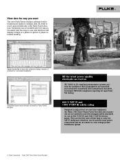
.... 600 V CAT IV and 1000 V CAT III safety rating Designed to help protect you want The new Fluke Power Analyze software revolutionizes your equipment, the Fluke 1750 Three-Phase Power Recorder and accessories are measured and calculated consistently with Fluke Power Analyze, thresholds can be modified after collection using a variety of standard or customized templates. Simplified report writer feature...
.... 600 V CAT IV and 1000 V CAT III safety rating Designed to help protect you want The new Fluke Power Analyze software revolutionizes your equipment, the Fluke 1750 Three-Phase Power Recorder and accessories are measured and calculated consistently with Fluke Power Analyze, thresholds can be modified after collection using a variety of standard or customized templates. Simplified report writer feature...
Fluke 1750 Three Phase Power Recorder Datasheet
Page 5
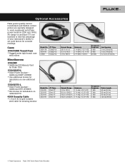
... (.78 in) dia. 2 cm (.78 in) dia. 3.2 cm (1.25 in ) 5 Fluke Corporation Fluke 1750 Three-Phase Power Recorder Additional SEAT LICENSE • One additional license for Fluke 1750 1750/SEAT-L • Fluke Power Analyze - Additional SITE LICENSE • Site license for installation on one additional PC 1750/SITE-L • Fluke Power Analyze - Optional Accessories Fluke power quality current transformers and flexible current probes are matched to...
... (.78 in) dia. 2 cm (.78 in) dia. 3.2 cm (1.25 in ) 5 Fluke Corporation Fluke 1750 Three-Phase Power Recorder Additional SEAT LICENSE • One additional license for Fluke 1750 1750/SEAT-L • Fluke Power Analyze - Additional SITE LICENSE • Site license for installation on one additional PC 1750/SITE-L • Fluke Power Analyze - Optional Accessories Fluke power quality current transformers and flexible current probes are matched to...
Fluke 1750 Three Phase Power Recorder Datasheet
Page 6
... and sampling PLL-synchronization source PLL lock range Sampling frequency A/D resolution The PLL synchronizes to the A-N voltage for wye power types, and to 100 % of current sensor range 6 Fluke Corporation Fluke 1750 Three-Phase Power Recorder All listed power types can be characterized as required by standards Ferromagnetic Clamps: ± (0.1 % full scale + 0.2 % reading + current sensor accuracy), valid for...
... and sampling PLL-synchronization source PLL lock range Sampling frequency A/D resolution The PLL synchronizes to the A-N voltage for wye power types, and to 100 % of current sensor range 6 Fluke Corporation Fluke 1750 Three-Phase Power Recorder All listed power types can be characterized as required by standards Ferromagnetic Clamps: ± (0.1 % full scale + 0.2 % reading + current sensor accuracy), valid for...
Fluke 1750 Three Phase Power Recorder Datasheet
Page 7
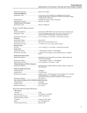
... distortion is measured for 3P4W lines) Displayed data Amplitude and duration of swell Measurement uncertainty Same as voltage dip Power Measurements Calculated per EN 61000-4-15:2003: 10 min (Pst), 2 h (Plt) 7 Fluke Corporation Fluke 1750 Three-Phase Power Recorder voltage between voltage fundamental and current fundamental Measurement range - 1.000 (leading) to + 1.000 (lagging) Measurement accuracy ± 0.5 % reading...
... distortion is measured for 3P4W lines) Displayed data Amplitude and duration of swell Measurement uncertainty Same as voltage dip Power Measurements Calculated per EN 61000-4-15:2003: 10 min (Pst), 2 h (Plt) 7 Fluke Corporation Fluke 1750 Three-Phase Power Recorder voltage between voltage fundamental and current fundamental Measurement range - 1.000 (leading) to + 1.000 (lagging) Measurement accuracy ± 0.5 % reading...
Fluke 1750 Three Phase Power Recorder Datasheet
Page 8
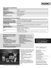
...10/2009 2428201F D-EN-N Modification of this document is a registered trademark of rugged and reliable test tools. 8 Fluke Corporation Fluke 1750 Three-Phase Power Recorder To learn more information call: In the U.S.A. (800) 443-5853 or Fax (425) 446-5116 In Europe/M-...Overvoltage Category 1000 V CAT III, 600 V CAT IV (anticipated overvoltage: 8000 V) Ordering information Fluke-1750 Three-Phase Power Recorder Includes: • 1750 acquisition unit • PDA wireless "front panel interface" and charger power plug adapters • 4 - 400 A current probes (3140R) • 5 test leads ...
...10/2009 2428201F D-EN-N Modification of this document is a registered trademark of rugged and reliable test tools. 8 Fluke Corporation Fluke 1750 Three-Phase Power Recorder To learn more information call: In the U.S.A. (800) 443-5853 or Fax (425) 446-5116 In Europe/M-...Overvoltage Category 1000 V CAT III, 600 V CAT IV (anticipated overvoltage: 8000 V) Ordering information Fluke-1750 Three-Phase Power Recorder Includes: • 1750 acquisition unit • PDA wireless "front panel interface" and charger power plug adapters • 4 - 400 A current probes (3140R) • 5 test leads ...

Fluke 1750 Calibration Manual
Page 11
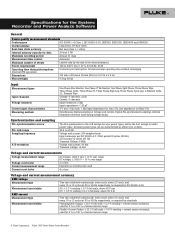
...Phase Split Phase, Three Phase Wye, Three Phase Delta, Three Phase IT, Three Phase High Leg, Three Phase Open Leg, 2 Element Delta, 2 ½ Element Wye Input Channels Voltage: 5 channels, AC/DC Current: 5 channels Voltage Channels Input resistance: 2 MΩ Input capacitance: Protective conductor terminal. Power Requirements 100 to Fluke's web site for recycling information. . Power Recorder...day Internal Memory Capacity for the System: Recorder and Power Analyze Software General Specifications Power Quality Measurement Standards Conformance IEC 61999-1-4 Class 1, IEC 61000-4-30 Class ...
...Phase Split Phase, Three Phase Wye, Three Phase Delta, Three Phase IT, Three Phase High Leg, Three Phase Open Leg, 2 Element Delta, 2 ½ Element Wye Input Channels Voltage: 5 channels, AC/DC Current: 5 channels Voltage Channels Input resistance: 2 MΩ Input capacitance: Protective conductor terminal. Power Requirements 100 to Fluke's web site for recycling information. . Power Recorder...day Internal Memory Capacity for the System: Recorder and Power Analyze Software General Specifications Power Quality Measurement Standards Conformance IEC 61999-1-4 Class 1, IEC 61000-4-30 Class ...
Fluke 1750 Calibration Manual
Page 13
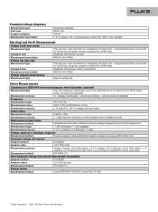
Power Recorder Specifications for the System: Recorder and Power Analyze Software Measurement Accuracy Same as rms voltage Voltage Dip (RMS sag) Measurement Type True rms (one cycle calculation by overlapping each half cycle) (voltage between lines is measured for 3P3W lines and phase... (lagging) Measurement Accuracy 1 digit from the calculation of each measured value (± 3 digits for total) Displacement Power Factor Measurement Method Calculated from the phase difference between voltage fundamental and current fundamental Measurement Range 1.000 (leading) to 0.000 to + 1.000 (lagging) ...
Power Recorder Specifications for the System: Recorder and Power Analyze Software Measurement Accuracy Same as rms voltage Voltage Dip (RMS sag) Measurement Type True rms (one cycle calculation by overlapping each half cycle) (voltage between lines is measured for 3P3W lines and phase... (lagging) Measurement Accuracy 1 digit from the calculation of each measured value (± 3 digits for total) Displacement Power Factor Measurement Method Calculated from the phase difference between voltage fundamental and current fundamental Measurement Range 1.000 (leading) to 0.000 to + 1.000 (lagging) ...
Fluke 1750 Calibration Manual
Page 17
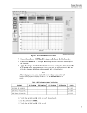
...Live View power analyze live view screen.bmp 7. Applied 60 Vrms @ Local Hz 240 Vrms @ Local Hz 600 Vrms @ Local Hz Table 4. Apply the voltages from Table 4 and list the Recorder readings for AN, BN and CN, all at the same amplitude and phase shift. Verify... that A, B, C, and J LEDs are on the Zoom to Fit box to STBY. 12. Connect the NORMAL LO to inputs A, B, C, and J of the Recorder. 8. of the graphical display, then click on . Note If the voltage goes over scale, right click on the voltage scale on the left margin of the Recorder. 9. Power Recorder...
...Live View power analyze live view screen.bmp 7. Applied 60 Vrms @ Local Hz 240 Vrms @ Local Hz 600 Vrms @ Local Hz Table 4. Apply the voltages from Table 4 and list the Recorder readings for AN, BN and CN, all at the same amplitude and phase shift. Verify... that A, B, C, and J LEDs are on the Zoom to Fit box to STBY. 12. Connect the NORMAL LO to inputs A, B, C, and J of the Recorder. 8. of the graphical display, then click on . Note If the voltage goes over scale, right click on the voltage scale on the left margin of the Recorder. 9. Power Recorder...

Fluke 1750 Calibration Manual
Page 19
...; Connect the calibrator NORMAL HI to 120.0 V @ 50 or 60 Hz on the NORMAL output and the values from Table 7 and list the Recorder readings for channels B, C, N, and J. 11. See Figure 6. Connect the calibrator AUX HI and LO to STBY. Set the calibrator output to ... NORMAL LO to voltages from Table 7 on the Recorder. 2. Press the WAVE MENUS softkey and ensure the phase angle is on the Recorder. 3. Set the calibrator to current input A using the current test cable. Press OPR. 8. Verify that the current LEDs turn off. 11 Power Recorder Verification Tests Table 6.
...; Connect the calibrator NORMAL HI to 120.0 V @ 50 or 60 Hz on the NORMAL output and the values from Table 7 and list the Recorder readings for channels B, C, N, and J. 11. See Figure 6. Connect the calibrator AUX HI and LO to STBY. Set the calibrator output to ... NORMAL LO to voltages from Table 7 on the Recorder. 2. Press the WAVE MENUS softkey and ensure the phase angle is on the Recorder. 3. Set the calibrator to current input A using the current test cable. Press OPR. 8. Verify that the current LEDs turn off. 11 Power Recorder Verification Tests Table 6.

Fluke 1750 Calibration Manual
Page 21
...Phase data. To Use Power Analyze to -last BN Triggered Phase Absolute value in the Event Summary table, the Absolute and Triggered Phase columns. 31. The following steps concern the two right-hand columns in Table 8. 35. Starting from the Triggered Phase data. 37. Click on 1750 Download, and then Save. 23. Record... Neutral is reached. Record the sixth-to compile event information. 22. Select all show up as NG for the UUT to -last N-triggered Phase Absolute value in Voltage Reference. 25. Click on the calibrator. 20. Power Recorder Verification Tests 17. ...
...Phase data. To Use Power Analyze to -last BN Triggered Phase Absolute value in the Event Summary table, the Absolute and Triggered Phase columns. 31. The following steps concern the two right-hand columns in Table 8. 35. Starting from the Triggered Phase data. 37. Click on 1750 Download, and then Save. 23. Record... Neutral is reached. Record the sixth-to compile event information. 22. Select all show up as NG for the UUT to -last N-triggered Phase Absolute value in Voltage Reference. 25. Click on the calibrator. 20. Power Recorder Verification Tests 17. ...
Fluke 1750 Operators Manual
Page 3
... Introduction...1 Contacting Fluke 2 Safety Information 3 Accessories ...4 Features...5 Applying the Front Panel Decal 7 Charging the PDA Battery 9 Installing the Software 9 Installing Power View on the PDA 9 Language Selection 10 PC System Requirement for Power Analyze 10 Installing Power Analyze 10 Installing the Power Recorder at a Facility 11 Work Flow...11 Installing the Recorder 12 Connecting the Recorder to the...
... Introduction...1 Contacting Fluke 2 Safety Information 3 Accessories ...4 Features...5 Applying the Front Panel Decal 7 Charging the PDA Battery 9 Installing the Software 9 Installing Power View on the PDA 9 Language Selection 10 PC System Requirement for Power Analyze 10 Installing Power Analyze 10 Installing the Power Recorder at a Facility 11 Work Flow...11 Installing the Recorder 12 Connecting the Recorder to the...

Fluke 1750 Operators Manual
Page 7
Three-Phase IT ...20 10. Connecting to the Recorder 25 15. Connecting the Supplemental Ground Terminal 8 4. Three-Phase Delta 19 9. Power View Menu Tree 28 v One-Phase Split Phase 17 7. Applying the Front Panel Decal 7 3. Three-Phase Wye 18 8. One Phase Plus Neutral 15 5. Three-Phase Open Leg 22 12. 2-Element Delta ...23 13. 2 ½-Element Wye 24 14. Three-Phase High Leg 21 11. List of Figures Figure Title Page 1. Fluke 1750 Power Recorder 5 2. One-Phase IT No Neutral 16 6.
Three-Phase IT ...20 10. Connecting to the Recorder 25 15. Connecting the Supplemental Ground Terminal 8 4. Three-Phase Delta 19 9. Power View Menu Tree 28 v One-Phase Split Phase 17 7. Applying the Front Panel Decal 7 3. Three-Phase Wye 18 8. One Phase Plus Neutral 15 5. Three-Phase Open Leg 22 12. 2-Element Delta ...23 13. 2 ½-Element Wye 24 14. Three-Phase High Leg 21 11. List of Figures Figure Title Page 1. Fluke 1750 Power Recorder 5 2. One-Phase IT No Neutral 16 6.

Fluke 1750 Operators Manual
Page 9
... incorrectly, you can swap the phase to another channel by changing an internal Recorder setting using . • Connection diagrams for power quality investigations. The 1750 Power Recorder, referred to hereafter as simply "the Recorder or the Product," consists of the 1750 Power Recorder are provided as a controller, you are available from the Recorder. Key features of a power recorder instrument, a wireless handheld Personal Digital...
... incorrectly, you can swap the phase to another channel by changing an internal Recorder setting using . • Connection diagrams for power quality investigations. The 1750 Power Recorder, referred to hereafter as simply "the Recorder or the Product," consists of the 1750 Power Recorder are provided as a controller, you are available from the Recorder. Key features of a power recorder instrument, a wireless handheld Personal Digital...

Fluke 1750 Operators Manual
Page 21
...range. • When a phase LED is BLINKING, you are correct before you can use the "Erase Memory" function and measurement 13 You can also use the ratio settings in pairs and cannot be attached to neutral. 4. Power Recorder Installing the Power Recorder at a Facility Note If ...your connection. Check the LED for example, 12000 V). 3. Connect the remaining current probes to the power network. • The arrow on the PDA or PC to make sure a connection is established. • When a phase LED is ON...
...range. • When a phase LED is BLINKING, you are correct before you can use the "Erase Memory" function and measurement 13 You can also use the ratio settings in pairs and cannot be attached to neutral. 4. Power Recorder Installing the Power Recorder at a Facility Note If ...your connection. Check the LED for example, 12000 V). 3. Connect the remaining current probes to the power network. • The arrow on the PDA or PC to make sure a connection is established. • When a phase LED is ON...

Fluke 1750 Operators Manual
Page 23
Power Recorder Power Type Diagrams A/L1 N GND azd02f.eps 15 One Phase Plus Neutral Example: Branch circuit at an outlet. Source ØA/L1 N GND POWER 1750 POWER RECORDER VOLTAGE A B C N 100-240 V 47-63 Hz ON CURRENT SD ETHERNET LINK BUSY Figure 4.
Power Recorder Power Type Diagrams A/L1 N GND azd02f.eps 15 One Phase Plus Neutral Example: Branch circuit at an outlet. Source ØA/L1 N GND POWER 1750 POWER RECORDER VOLTAGE A B C N 100-240 V 47-63 Hz ON CURRENT SD ETHERNET LINK BUSY Figure 4.

Fluke 1750 Operators Manual
Page 24
One-Phase IT No Neutral azd14f.eps Example: Used in Norway and in some hospitals. 1750 Operators Manual GND A/L1 GND B/L2 POWER 1750 POWER RECORDER VOLTAGE A B C N 100-240 V 47- 63 Hz ON CURRENT SD ETHERNET LINK BUSY Figure 5. This would be the connection at a branch circuit. 16
One-Phase IT No Neutral azd14f.eps Example: Used in Norway and in some hospitals. 1750 Operators Manual GND A/L1 GND B/L2 POWER 1750 POWER RECORDER VOLTAGE A B C N 100-240 V 47- 63 Hz ON CURRENT SD ETHERNET LINK BUSY Figure 5. This would be the connection at a branch circuit. 16

Fluke 1750 Operators Manual
Page 25
Power Recorder Power Type Diagrams A/L1 N GND B/L2 POWER 1750 POWER RECORDER VOLTAGE A B C N 100-240 V 47-63Hz ON CURRENT SD ETHERNET LINK BUSY Figure 6. azd03f.eps 17 One-Phase Split Phase Example: A North American residential installation at the service entrance.
Power Recorder Power Type Diagrams A/L1 N GND B/L2 POWER 1750 POWER RECORDER VOLTAGE A B C N 100-240 V 47-63Hz ON CURRENT SD ETHERNET LINK BUSY Figure 6. azd03f.eps 17 One-Phase Split Phase Example: A North American residential installation at the service entrance.


